
System Features
New system features include:
- FortiExtender Support
- Using a Virtual WAN Link for Redundant Internet Connections
- FortiGuard Services
- Netflow v9.0
- DHCP Server Configuration
- Improvements to Aggregate/Redundant Interfaces
- Link Layer Discovery Protocol
- CPU and Memory Usage per VDOM
- Custom Languages for Guest Management and SSL VPN Portals
- Packet Capture Options for Admin Profiles
- FortiCloud Modem List
- SPAN Support for Hard-Switch Interfaces
- Setting the Service and AC-name in PPOE PADI/PADO Negotiations
- Disabling FortiExplorer, the USB MGMT Port, and the Serial Console
- Port Kernel Profiling
- Using a Second Destination IP (VRDST)
- Session Rate Stats per VDOM
- Disable Honoring the Don't-Fragment Flag
- Disable Login Time Recording
- Per-IP-Bandwidth-Usage Feature Removed
- Modem Support
FortiExtender Support
FortiOS 5.2 supports the new FortiExtender unit, which provides internet connectivity via 4G/LTE network to a FortiGate unit.
To connect a FortiGate and FortiExtender, a new tap interface is created on the FortiGate unit, which receives the IP address from the cellular service provider via the FortiExtender, using a CAPWAP data channel. All the packets sent to the tap interface are received by the extender module on the FortiGate and are then sent to the FortiExtender, which then sends the packets out on the 4G/LTE network.
When data packets are received from the cellular network, the FortiExtender passes the packets to the FortiGate via the CAPWAP data channel. These packets are written to the tap interface and the FortiGate IP stack will process them.
The options to configure a FortiExtender unit can be found by going to System > Network > FortiExtender.
|
|
The configuration of a FortiExtender interface is restricted to the root VDOM. |
Connecting a FortiExtender unit to a FortiGate unit
- If you are using the provided PoE injector:
- Plug the provided Ethernet cable into the Ethernet port of the FortiExtender and insert the other end of the Ethernet cable into the AP/Bridge port on the injector, then plug the injector into an electrical outlet.
- Connect the LAN port of the PoE injector to a FortiGate, FortiWifi, or FortiSwitch device.
- If you are not using the PoE injector, insert the other end of the Ethernet cable into a PoE LAN port on an appropriate FortiGate, FortiWiFi or FortiSwitch device.
- By default, the options for the FortiExtender are hidden and disabled. Enable them in FortiGate’s CLI:
config system global
set fortiextender enable
set wireless-controller enable
end
- Enable the control and provisioning of Wireless Access Point (CAPWAP) service on the port to which the FortiExtender unit is connected (lan interface in this example) using the following CLI commands:
config system interface
edit lan
set allowaccess capwap
end
end
Once enabled, it appears as a virtual WAN interface in the FortiGate, such as fext-wan1.
Configuring the FortiExtender unit
- At this point, you can fully manage the FortiExtender from the FortiGate unit. To achieve this, you need to authorize the FortiExtender by going to System > Network > FortiExtender and click on Authorize. Once authorized, you can configure the following settings as required:
- Link Status: Shows you if the link is Up or Down, click on Details to see the System and Modem Status.
- IP Address: Shows you the current FortiExtender’s IP address, click on the link of the IP address to connect to the FortiExtender GUI.
- OS Version: Shows the current FortiExtender’s build, click on Upgrade if you wish to upgrade the Firmware.
- Configure Settings: Allows you to configure the Modem Settings (for more information, see below), PPP Authentication, General, GSM / LTE, and CDMA .
- Diagnostics: Allows you to diagnose the FortiExtender unit, you can choose a command form the existing commands and click on Run. Existing commands are:
Show device info, Show data session connection status, test connection, test disconnection, Get signal strength, AT Command.
The FortiExtender unit allows for two modes of operation for the modem; On Demand and Always Connect. In On Demand mode, the modem connects to a dialup ISP account to provide the connection to the Internet when needed. In Always Connect mode, the modem is always connected to the internet, it can acts as a primary or backup method of connecting to the Internet. To configure the dial mode as needed, do the following:
- Select Configure Settings.
- Extend Modem Settings.
- Select the Dial Mode of Always Connect or On Demand.
- Enter the Quota Limit to the desired limit in Mega Byte.
- Select OK.
Configuring the FortiGate unit
- Go to Router > Static > Static Routes or System > Network > Routing, depending on your FortiGate model, and select Create New.
|
|
If your network will be using IPv6 addresses, go to Router > Static > Static Routes or System > Network > Routing and select IPv6 Route. |
- Set the Destination IP/Mask to 0.0.0.0/0.0.0.0, Device to fext-wan1, and set the Gateway to your gateway IP or to the next hop router, depending on your network requirements.
- Select OK.
- Go to Policy & Objects > Policy > IPv4 and select Create New.
|
|
If your network will be using IPv6 addresses, go to Policy & Objects > Policy > IPv6 and select Create New. |
- Set the Incoming Interface to the internal interface and the Outgoing Interface to fext-wan1 interface. You will also need to set Source Address, Destination Address, Schedule, and Service according to your network requirements.
- Make sure the Action is set to ACCEPT. Turn on NAT and make sure Use Destination Interface Address is selected.
- Select OK.
Using a Virtual WAN Link for Redundant Internet Connections
To make sure your network is always connected to the Internet you can engage the services of two or more Internet service providers and set up redundant Internet connections. Then, if one of your ISPs service is interrupted, all of your Internet traffic can be switched to the other ISP, maintaining your Internet connection. Also, while both ISPs are operating you can load balance traffic between them, increasing your network’s available Internet bandwidth.
Previous versions of FortiOS required a few steps to set up two interfaces as redundant Internet connections. The setup also involved some special routing and load balancing setup and creating duplicate policy configurations for each Internet facing interface. In addition, previous versions of FortiOS supported basic link monitoring.
FortiOS 5.2 adds a new type of interface called a virtual WAN link. A virtual WAN link consists of two or more physical interfaces that are connected to two or more ISPs and to the Internet as well as the load balancing and routing configuration required to support redundant internet connections. In addition, the virtual WAN link configuration also includes new link health checking and settings to control traffic flow based on link health.
The FortiGate unit sees the virtual WAN link as a single interface so the FortiGate’s security policy configuration no longer has be redundant to support dual Internet links. Now one policy configuration to control traffic to the virtual WAN link is all that is required. You can also add or remove redundant Internet links just by adding or removing physical interfaces from the virtual WAN link. No addition changes to the routing, load balancing or firewall policy configuration are required.
Setting Up a Virtual WAN Link
To set up a virtual WAN link, go to System > Network > Interfaces and select Create New > Virtual WAN. Add the interfaces connected to ISPs to the virtual WAN link. For each interface you must enter a gateway IP, usually provided by your ISP. You can also change load balancing settings (such as Spillover Threshold and Weight) and set up link health checking (called measuring link quality).
Virtual WAN link configuration
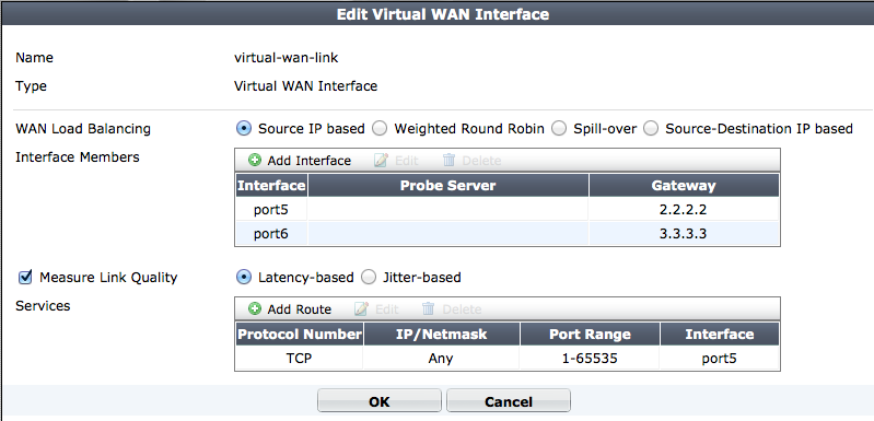
Once you have added interfaces to the virtual WAN interface you should go to Router > Static > Static Route and add a default route for the virtual WAN link. Then add firewall policies that allow access to the Internet by setting the outgoing interface to virtual-wan-link.
For more information about using a virtual WAN link, please see the FortiGate Cookbook recipe Redundant Internet connections (5.2.0) .
Setting Up Virtual WAN Link Load Balancing
By default when you set up a virtual WAN link source IP based load balancing is selected and traffic is load balanced among the interfaces added to virtual WAN link configuration. You can change the load balancing method to weighted load balancing, spill-over load balancing or source-destination IP load balancing. Selecting a different load balancing method may also require configuring the interfaces added to the virtual WAN link to add weights (for weighted load balancing) or to set spillover thresholds.
Directing Traffic to Higher Quality Links
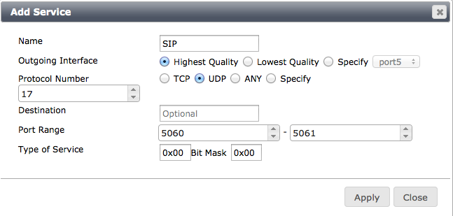
You can configure link quality measuring (link health checking) on the interfaces added to the virtual WAN link. Depending on how you configure the virtual WAN link this link quality checking is based on latency or jitter. With link quality checking in place you can configure Services to control the links used for selected types of traffic. For example, media-based traffic like SIP is very sensitive to jitter. If you set up link quality checking to check for jitter, you can configure the virtual WAN link to send SIP traffic to the link with the lowest jitter (and so the highest quality link).
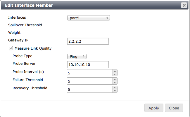
To configure link checking on individual interfaces added to a virtual WAN link, edit Interface members in the virtual WAN link, select Measure Link Quality and set the quality measurement options. You can measure link quality using ping or HTTP, select a server to communicate with to perform link quality checking and set the probe interval, failure threshold and recovery threshold.
Configuring link health checking
Next, add Services that control how traffic patterns are affected by link quality. Services work like policy routes. Configure a service by defining a traffic type (for example, SIP) and specifying whether this traffic always goes to the highest quality interface, the lowest quality interface or a specific interface no matter the quality.
Virtual WAN link service
Measured Volume Based Distribution
Your FortiGate can actively measure the volume of traffic sent to each WAN link and distribute new sessions to balance the traffic volume to each link using a simple ratio calculation. To use this feature, use the following CLI command:
config system virtual-wan-link
set load-balance-mode measured-volume-based
config member
edit <ID>
set volume-ratio <number>
end
end
end
The Link Monitor
You can monitor link health using the Link monitor, which can be found by going to System > Monitor > Link Monitor.
FortiGuard Services
Several changes have been made to how FortiGuard services can be received by your FortiGate unit.
FortiGuard Server List
In FortiOS 5.2, you can create a server list for receiving FortiGuard updates, allowing you to use different servers for different FortiGuard services. Each server can be used for either web filter and anti-spam ratings or AV/IPS signature updates.
The server list also has the ability to include the default servers by adding them to the end of the list. This option is only available if the central management type is not set to FortiGuard.
If no server list is configured, the FortiGuard will not use the public FortiGuard servers as resolved by DNS.
Syntax
config system central-management
config server-list
edit <ID>
set server-type {rating | update}
set server-address <address>
end
set include-default-servers {enable | disable}
end
Using TCP Port 80 to Receive Updates from a FortiManager Unit
Communications to a FortiManager unit in order to receive FortiGuard updates are now supported using TCP port 80.
To configure communications to use port 80, go to System > Config > FortiGuard and expand Web Filtering and Email Filtering Options. Select Use Alternate Port (80). This can also be configured using the CLI.
Syntax
config system fortiguard
set port 80
end
FortiGuard TCP stats can also be displayed using the diagnose test application urlfilter 20 command.
Netflow v9.0
FortiOS 5.2 supports Netflow v9.0. NetFlow services provide network administrators with access to IP flow information from their data networks. Network elements (routers and switches) gather flow data and export it to collectors. The collected data provides fine-grained metering for highly flexible and detailed resource usage accounting.
A flow is defined as a unidirectional sequence of packets with some common properties that pass through a network device. These collected flows are exported to an external device, the NetFlow collector. Network flow records include details such as IP addresses, packet and byte counts, timestamps, application ports, and input and output interfaces.
Configuring the Global Settings for Netflow Collector and Timers
The global settings for Netflow can be configured in the CLI:
config system netflow
set collector-ip <address>
set collector-port <port>
set source-ip <address>
set active-flow-timeout <integer>
set inactive-flow-timeout <integer>
end
The value for active-flow-timeout is used as the minimum length of a live session, as well as for the intervals to send the report. The default is 1 minute, meaning that if a session lives for a minute, it will be reported in a Netflow packet.
The value for inactive-flow-timeout is used as the interval to send a Netflow report of inactive (finished) flows. Since FortiOS uses 1350 Byte payloads, the number of reports in a packet are limited and multiple packets may be sent regardless of this timer.
Using Netflow with VDOMs
For VDOM environments, excluding the management VDOM, Netflow must be configured using the following CLI commands:
config system vdom-netflow
set vdom-netflow enable
set collector-ip <address>
set collector-port <port>
set source-ip <address>
end
Adding Netflow Sampling to an Interface
Netflow sampling can be enabled on an interface to sample transmitted traffic (tx), received traffic (rx), or both using the CLI:
config system interface
edit <name>
set netflow-sampler {disable | tx | rx | both}
end
end
Viewing the Configuration
Netflow does not have a separate daemon and is instead running under sflowd. The current Netflow configuration can be viewed by using test level 3 or 4:
diagnose test application sflowd 3
diagnose test application sflowd 4
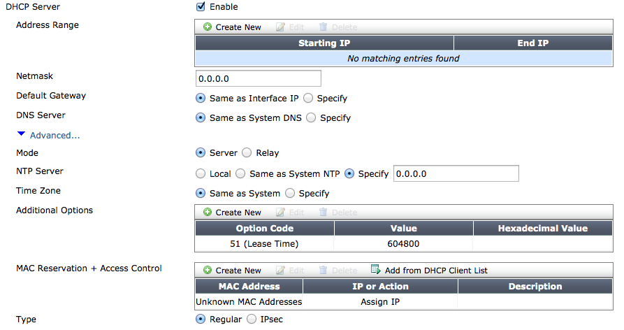
DHCP Server Configuration
The following attributes have been added for DHCP server configuration to both the web-based manager and the CLI:
- Time zone
- TFTP server
- TFTP filename
DCHP server settings
Syntax
config system dhcp server
edit <integer>
set timezone-option {disable | default | specify}
set timezone <timezone_code>
set tftp-server <string>
set filename <file_name>
end
end
Improvements to Aggregate/Redundant Interfaces
Several improvements have been made in FortiOS 5.2 for aggregate or redundant interfaces.
Minimum Number of Links in an Aggregation
You can now set a minimum number of links that must exist in an aggregation. If this number is not reached, the device will failover. The minimum links value can be set between 1-32, with 1 being the default value.
Aggregates can also now be configured so that they are taken down administratively when the min-links threshold is passed. This will cause all the members to be taken down administratively as well.
Syntax
config system interface
edit <name>
set type aggregate
set vdom root
set member <ports>
set min-links <integer>
set min-links-down administrative
end
end
Avoiding Traffic Disturbances
Two new methods have been added to avoid traffic disturbances for an aggregate that can be caused by ports flapping up and down and being repeatedly added and removed from the aggregate.
Setting the Link Up Delay Period
When a member port in an aggregate/redundant becomes operationally up, be default it is considered as a viable port for aggregation/redundancy after 50ms. Increasing this delay can minimizing the effect of a flapping port by causing the FortiGate to wait longer before deciding if a port is considered viable. This option is available for both redundant and aggregate interfaces.
Syntax
config system interface
edit <name>
set type {aggregate | redundant}
set link-up-delay <time>
end
end
Enabling Priority Override
In the case of a redundant port, there is only one port actively carrying traffic thus the only time a port coming up can affect existing traffic is where the primary port went down, traffic moved to a secondary and then the primary came back up. In this case since there is only one port the impact of switching ports is more noticeable and thus it may be desirable to not switch back to the original primary just because it is up. Instead traffic should only switch back if the currently active secondary fails.
To support that, the command set priority-override has been added for redundant interfaces. If priority-override is enabled, then when a port with a higher priority comes up then traffic switches to it. With priority-override disabled, traffic will only switch to a higher priority port if the current port fails.
Syntax
config system interface
edit <name>
set type redundant
set priority-override {enable | disable}
end
end
Link Layer Discovery Protocol
Link Layer Discovery Protocol (LLDP) is supported in FortiOS 5.2. LLDP allows a device to advertise its existence and capabilities to other devices.
The primary use for LLDP is to improve a FortiGate unit's device detection output when another FortiGate unit is detected. LLDP information is used to populate the device record on the FortiGate unit performing device detection. Any LLDP information transmitted by a peer is ignored unless FortiGate device detection is enabled on an interface. If device detection is enabled, then the subset of LLDP information sent by the peer that is relevant to device detection is shown in the diagnose user device list output.
The transmitted LLDP attributes on a given port are:
- Chassis ID
- Port ID
- TTL
- System Name
- System Description
- System Capabilities
- Aggregation
- Host Name
LLDP transmission is enabled by default on all ports that support a MAC address. It can be disabled globally, or disabled on some interfaces or VDOMs, while being enabled on others.
Syntax
To disable LLDP globally or on a specific VDOM, use the following command:
config system global
set lldp-transmission disable
end
To enable LLDP at the individual interface level, first disable LLDP globally, then use the following command:
config system interface
edit <name>
set lldp-transmission enable
end
end
CPU and Memory Usage per VDOM
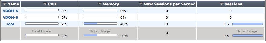
In FortiOS 5.2, the following information sources are available concerning both CPU and memory usage per VDOM:
Default columns for CPU and Memory have been added to the VDOM list.
Optional columns for Sessions and New Sessions per Second have been added to the VDOM list.
A summary line has been added to at the bottom of the VDOM list to show global CPU, memory, sessions, and sessions per second usage.
The CLI command diagnose sys vd stats has been added to display VDOM statistics.
VDOM list
Custom Languages for Guest Management and SSL VPN Portals
Custom language files can now be used for guest management admin accounts, as well as guest portals, SSL VPN portals, and SSL VPN user settings.
To use this feature, it must be enabled in the CLI. Language files can now be managed, imported, and downloaded by going to System > Config > Advanced. Further configuration can be done in the CLI.
Syntax
- Enabling the feature:
config system global
set gui-custom-language enable
end
- Downloading a custom language file from a TFTP server:
execute system custom-language import <lang_name> <file_name> <tftp_server_ip>
- Managing custom languages:
config system custom-language
edit <lang_name>
set filename <file_name>
end
end
- Setting the custom language for an admin account with
guest-authenabled:
config system admin
edit <name>
set guest-auth enable
set guest-lang <lang_name>
end
end
- Setting the custom language for an SSL-VPN portal with
web-modeenabled:
config vpn ssl interface
edit <name>
set web-mode enable
set custom-lang <lang_name>
end
end
- Setting the custom language for an SSL-VPN user:
config vpn ssl web user-bookmark
edit <name>
set custom-lang <lang_name>
end
end
Packet Capture Options for Admin Profiles
Packet capture can now be configured in an admin profile and set to None, Read Only, or Read-Write. The packet capture option can be found by going to System > Admin > Admin Profiles and expanding Firewall Configuration.
This feature can also be configured in the CLI.
Syntax
config system accprofile
edit <name>
set fwgrp custom
config fwgrp-permission
set packet-capture {read-only | read-write | none}
end
end
end
FortiCloud Modem List
The supported modem list that can be downloaded from FortiCloud will now include a list of supported modems by FortiOS and the new FortiExtender unit. To support this, the file format of the list changed from plain text to tar ball that contains two files: modem_list.conf for the FortiOS list and modem_list_fex.conf for the FortiExtender list.
SPAN Support for Hard-Switch Interfaces
The Switch Port Analyzer (SPAN) feature is now available for hardware switch interfaces on FortiGate models with built-in hardware switches (for example, the FortiGate-100D, 140D, and 200D etc.). The SPAN feature (also called port mirroring) allows you to send a copy of the packets received or sent by one interface to another. So, for example, you could send all traffic received by the WAN interface to another interface and connect a sniffer to that other interface to monitor the traffic on the WAN interface.
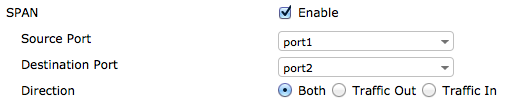
To enable SPAN on a hardware switch, go to System > Network > Interfaces and edit a hardware switch interface. By default the system may have a hardware switch interface called lan. You can also create a new hardware switch interface.
Select the SPAN checkbox. Select a source port from which traffic will be mirrored. Select the destination port to which the mirrored traffic is sent. Select to mirror traffic received, traffic sent, or both.
Configuring SPAN
You can also enable SPAN in the CLI:
Syntax
config system virtual-switch
edit <port>
set span enable
set span-source-port <port>
set span-dest-port <port>
set span-direction {both | Tx | Rx}
end
end
Setting the Service and AC-name in PPOE PADI/PADO Negotiations
The Service and AC name in the PPPoE PADI/PADO negotiation is now configurable. This allows CLI-specified names to encoded, enhancing logic in the handling of various PPPoE server responses, especially in situations where there are multiple Access Concentrator servers in the Point of Presence site.
Syntax
edit port1
set mode pppoe
set service-name <name>
set ac-name <name>
end
Disabling FortiExplorer, the USB MGMT Port, and the Serial Console
New CLI commands have been added allowing you to disable access for FortiExplorer on Windows and OS X and the USB MGMT port, or for the serial console, FortiExplorer iOS, the USB MGMT port, and 3G/4G MODEM access.
Syntax
- Disable FortiExplorer on Windows and OS X and the USB MGMT port:
config system console
set fortiexplorer disable
end
- Disable serial console, FortiExplorer iOS, and 3G/4G MODEM access:
config system console
set login disable
end
Port Kernel Profiling
Port kernel profiling is now supported in FortiOS 5.2. To use this feature, enter the command diagnose sys profile into the CLI. If you press enter, the following options are available:
- set cpu mask
- run start command
- run stop command to read the profiling data and analyze
- run show command to show the result
- set cpu mask 00 to stop profiling
The following attributes are also available:
cpumask- profile which CPUs.module- show kernel module (This is only available when the kernel is module mode).show- show kernel profiling result.start- start kernel profiling data.stop- copy kernel profiling data.sysmap- show kernel sysmap.
Using a Second Destination IP (VRDST)
VRRP can now be configured with second destination IP (VRDST) for monitoring. When two IPs are used, VRRP failure will only be reported if both monitored IPs are down.
A second VRDST can be configured using the CLI.
Syntax
config system interface
edit <interface>
config vrrp
edit <id>
set vrdst <ip1> <ip2>
end
end
end
Session Rate Stats per VDOM
The command diagnose sys vd list now displays the session setup rate. This feature is supported for both IPv4 and IPv6.
Disable Honoring the Don't-Fragment Flag
Honoring the Don't-Fragment flag can now be disabled through the CLI. This allows the FortiGate unit to fragment the packet as required, even when the Don't-Fragment flag is set.
Syntax
config system global
set honor-df disable
end
Disable Login Time Recording
Login time recording, which is enabled by default, can now be disabled using the CLI.
Syntax
config system global
set login-timestamp disable
end
Per-IP-Bandwidth-Usage Feature Removed
The Per-IP-Bandwidth feature has been removed in FortiOS 5.2. This includes both the Per-P-Bandwidth widget in the web-based manager and all related CLI commands.
Modem Support
The Novatel MC679 and Sierra 313U modems are supported in FortiOS 5.2 for use with a FortiGate unit.
An MIB entry, fgUsbModemSignalStrength, has also been added to display modem signal strength.
Copyright © 2018 Fortinet, Inc. All Rights Reserved. | Terms of Service | Privacy Policy
