
Configuration examples
This chapter provides the basic examples to illustrate WAN optimization configurations introduced in the previous chapters.
Example Basic manual (peer-to-peer) WAN optimization configuration
In a manual (peer to peer) configuration the WAN optimization tunnel can be set up between one client-side FortiGate unit and one server-side FortiGate unit. The peer ID of the server-side FortiGate unit is added to the client-side WAN optimization policy. When the client-side FortiGate unit initiates a tunnel with the server-side FortiGate unit, the packets that initiate the tunnel include information that allows the server-side FortiGate unit to determine that it is a manual tunnel request. The server-side FortiGate unit does not require a WAN optimization profile; you just need to add the client peer host ID and IP address to the server-side FortiGate unit peer list and from the CLI an explicit proxy policy to accept WAN optimization tunnel connections.
In a manual WAN optimization configuration, you create a manual WAN optimization security policy on the client-side FortiGate unit. To do this you must use the CLI to set wanopt-detection to off and to add the peer host ID of the server-side FortiGate unit to the WAN optimization security policy.
Network topology and assumptions
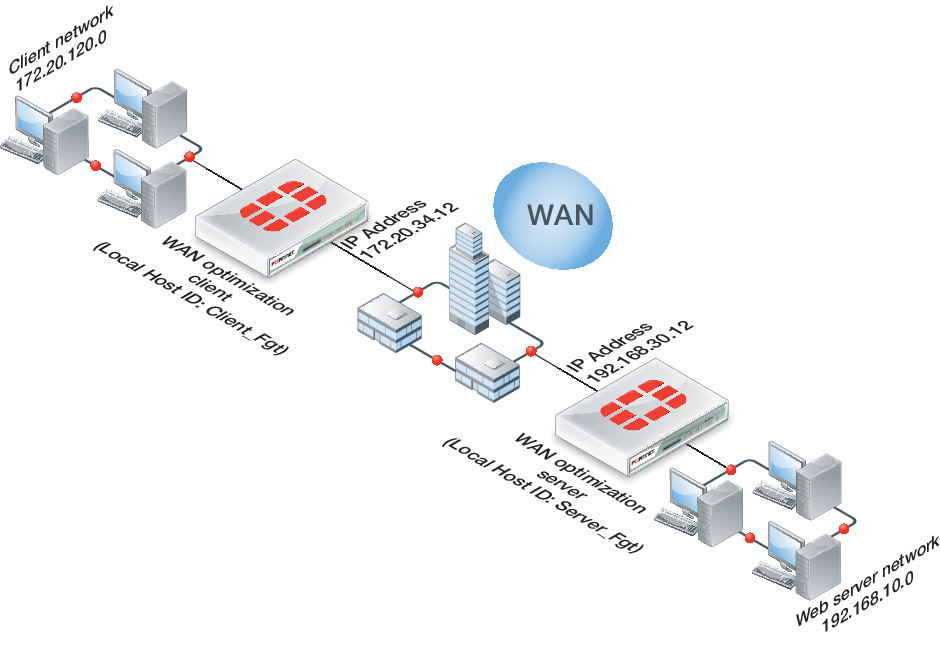
This example configuration includes a client-side FortiGate unit called Peer-Fgt-1 with a WAN IP address of 172.20.34.12. This unit is in front of a network with IP address 172.20.120.0. The server-side FortiGate unit is called Peer-Fgt-2 with a WAN IP address of 192.168.30.12. This unit is in front of a web server network with IP address 192.168.10.0.
This example customizes the default WAN optimization profile on the client-side FortiGate unit and adds it to the WAN optimization policy. You can also create a new WAN optimization profile.
Example manual (peer-to-peer) topology
General configuration steps
This section breaks down the configuration for this example into smaller procedures. For best results, follow the procedures in the order given:
- Configure the client-side FortiGate unit:
- Add peers.
- Configure the default WAN optimization profile to optimize HTTP traffic.
- Add a manual WAN optimization security policy.
- Configure the server-side FortiGate unit:
- Add peers.
- Add a WAN optimization tunnel policy.
Configuring basic peer-to-peer WAN optimization - web-based manager
Use the following steps to configure the example configuration from the web-based manager.
To configure the client-side FortiGate unit
- Go to WAN Opt. & Cache > WAN Opt. Peers > Peers and enter a Local Host ID for the client-side FortiGate unit:
| Local Host ID | Client-Fgt |
- Select Apply.
- Select Create New and add the server-side FortiGate unit Peer Host ID and IP Address for the server-side FortiGate:
| Peer Host ID | Server-Fgt |
| IP Address | 192.168.30.12 |
- Select OK.
- Go to Policy & Objects > Objects > Addresses and select Create New to add a firewall address for the client network.
| Category | Address |
| Name | Client-Net |
| Type | Subnet |
| Subnet / IP Range | 172.20.120.0/24 |
| Interface | port1 |
- Select Create New to add a firewall address for the web server network.
| Category | Address |
| Name | Web-Server-Net |
| Type | Subnet |
| Subnet / IP Range | 192.168.10.0/24 |
| Interface | port2 |
- Go to WAN Opt. & Cache > WAN Opt. Profiles > Profiles and edit the default profile.
- Select Transparent Mode.
- Under Protocol, select HTTP and for HTTP select Byte Caching. Leave the HTTP Port set to 80.
- Select Apply to save your changes.
- Go to Policy& Objects > Policy > IPv4 and add a WAN optimization security policy to the client-side FortiGate unit that accepts traffic to be optimized:
| Incoming Interface | port1 |
| Source Address | all |
| Outgoing Interface | port2 |
| Destination Address | all |
| Schedule | always |
| Service | ALL |
| Action | ACCEPT |
- Select Enable WAN Optimization and configure the following settings:
| Enable WAN Optimization | active |
| Profile | default |
- Select OK.
- Edit the policy from the CLI to turn off
wanopt-detection, add the peer ID of the server-side FortiGate unit, and the default WAN optimization profile. The following example assumes the ID of the policy is 5:
config firewall policy
edit 5
set wanopt-detection off
set wanopt-peer Server-Fgt
set wanopt-profile default
end
When you set the detection mode to
offthe policy becomes a manual mode WAN optimization policy. On the web-based manager the WAN optimization part of the policy changes to the following:
| Enable WAN Optimization | Manual (Profile: default, Peer: Peer-Fgt-2) |
To configure the server-side FortiGate unit
- Go to WAN Opt. & Cache > WAN Opt. Peers > Peers and enter a Local Host ID for the server-side FortiGate unit:
| Local Host ID | Server-Fgt |
- Select Apply.
- Select Create New and add a Peer Host ID and the IP Address for the client-side FortiGate unit:
| Peer Host ID | Client-Fgt |
| IP Address | 172.20.34.12 |
- Select OK.
- Enter the following CLI command to add an explicit proxy policy to accept WAN optimization tunnel connections.
configure firewall explicit-proxy-policy
edit 0
set proxy wanopt
set dstintf port1
set srcaddr all
set dstaddr all
set action accept
set schedule always
set service ALL
next
end
Configuring basic peer-to-peer WAN optimization - CLI
Use the following steps to configure the example WAN optimization configuration from the client-side and server-side FortiGate unit CLI.
To configure the client-side FortiGate unit
- Add the Local Host ID to the client-side FortiGate configuration:
config wanopt settings
set host-id Client-Fgt
end
- Add the server-side Local Host ID to the client-side peer list:
config wanopt peer
edit Server-Fgt
set ip 192.168.30.12
end
- Add a firewall address for the client network.
config firewall address
edit Client-Net
set type ipmask
set subnet 172.20.120.0 255.255.255.0
set associated-interface port1
end
- Add a firewall address for the web server network.
config firewall address
edit Web-Server-Net
set type ipmask
set subnet 192.168.10.0 255.255.255.0
set associated-interface port2
end
- Edit the default WAN optimization profile, select transparent mode, enable HTTP WAN optimization and enable byte caching for HTTP. Leave the HTTP Port set to 80.
config wanopt profile
edit default
set transparent enable
config http
set status enable
set byte-caching enable
end
end
- Add a WAN optimization security policy to the client-side FortiGate unit to accept the traffic to be optimized:
config firewall policy
edit 0
set srcintf port1
set dstintf port2
set srcaddr all
set dstaddr all
set action accept
set service ALL
set schedule always
set wanopt enable
set wanopt-profile default
set wanopt-detection off
set wanopt-peer Server-Fgt
end
To configure the server-side FortiGate unit
- Add the Local Host ID to the server-side FortiGate configuration:
config wanopt settings
set host-id Server-Fgt
end
- Add the client-side Local Host ID to the server-side peer list:
config wanopt peer
edit Client-Fgt
set ip 192.168.30.12
end
- Add a WAN optimization tunnel explicit proxy policy.
configure firewall explicit-proxy-policy
edit 0
set proxy wanopt
set dstintf port1
set srcaddr all
set dstaddr all
set action accept
set schedule always
set service ALL
next
end
Testing and troubleshooting the configuration
To test the configuration attempt to start a web browsing session between the client network and the web server network. For example, from a PC on the client network browse to the IP address of a web server on the web server network, for example http://192.168.10.100. Even though this address is not on the client network you should be able to connect to this web server over the WAN optimization tunnel.
If you can connect, check WAN optimization monitoring (go to WAN Opt. & Cache > Monitor > Monitor). If WAN optimization has been forwarding the traffic the WAN optimization monitor should show the protocol that has been optimized (in this case HTTP) and the reduction rate in WAN bandwidth usage.
If you can’t connect you can try the following to diagnose the problem:
- Review your configuration and make sure all details such as address ranges, peer names, and IP addresses are correct.
- Confirm that the security policy on the client-side FortiGate unit is accepting traffic for the 192.168.10.0 network. You can do this by checking the policy monitor (Policy & Objects > Monitor > Policy Monitor). Look for sessions that use the policy ID of this policy.
- Check routing on the FortiGate units and on the client and web server networks to make sure packets can be forwarded as required. The FortiGate units must be able to communicate with each other, routing on the client network must allow packets destined for the web server network to be received by the client-side FortiGate unit, and packets from the server-side FortiGate unit must be able to reach the web servers.
You can use the following get and diagnose commands to display information about how WAN optimization is operating.
Enter the following command to list all of the running WAN optimization tunnels and display information about each one. The command output for the client-side FortiGate unit shows 10 tunnels all created by peer-to-peer WAN optimization rules (auto-detect set to off).
diagnose wad tunnel list
Tunnel: id=100 type=manual
vd=0 shared=no uses=0 state=3
peer name=Web-servers id=100 ip=192.168.30.12
SSL-secured-tunnel=no auth-grp=
bytes_in=348 bytes_out=384
Tunnel: id=99 type=manual
vd=0 shared=no uses=0 state=3
peer name=Web-servers id=99 ip=192.168.30.12
SSL-secured-tunnel=no auth-grp=
bytes_in=348 bytes_out=384
Tunnel: id=98 type=manual
vd=0 shared=no uses=0 state=3
peer name=Web-servers id=98 ip=192.168.30.12
SSL-secured-tunnel=no auth-grp=
bytes_in=348 bytes_out=384
Tunnel: id=39 type=manual
vd=0 shared=no uses=0 state=3
peer name=Web-servers id=39 ip=192.168.30.12
SSL-secured-tunnel=no auth-grp=
bytes_in=1068 bytes_out=1104
Tunnel: id=7 type=manual
vd=0 shared=no uses=0 state=3
peer name=Web-servers id=7 ip=192.168.30.12
SSL-secured-tunnel=no auth-grp=
bytes_in=1228 bytes_out=1264
Tunnel: id=8 type=manual
vd=0 shared=no uses=0 state=3
peer name=Web-servers id=8 ip=192.168.30.12
SSL-secured-tunnel=no auth-grp=
bytes_in=1228 bytes_out=1264
Tunnel: id=5 type=manual
vd=0 shared=no uses=0 state=3
peer name=Web-servers id=5 ip=192.168.30.12
SSL-secured-tunnel=no auth-grp=
bytes_in=1228 bytes_out=1264
Tunnel: id=4 type=manual
vd=0 shared=no uses=0 state=3
peer name=Web-servers id=4 ip=192.168.30.12
SSL-secured-tunnel=no auth-grp=
bytes_in=1228 bytes_out=1264
Tunnel: id=1 type=manual
vd=0 shared=no uses=0 state=3
peer name=Web-servers id=1 ip=192.168.30.12
SSL-secured-tunnel=no auth-grp=
bytes_in=1228 bytes_out=1264
Tunnel: id=2 type=manual
vd=0 shared=no uses=0 state=3
peer name=Web-servers id=2 ip=192.168.30.12
SSL-secured-tunnel=no auth-grp=
bytes_in=1228 bytes_out=1264
Tunnels total=10 manual=10 auto=0
Example Active-passive WAN optimization
In active-passive WAN optimization you add an active WAN optimization policy to the client-side FortiGate unit and you add a WAN optimization tunnel policy and a passive WAN optimization policy to the server-side FortiGate unit.
The active policy accepts the traffic to be optimized and sends it down the WAN optimization tunnel to the server-side FortiGate unit. The active policy can also apply security profiles and other features to traffic before it exits the client-side FortiGate unit.
A tunnel explicit proxy policy on the sever-side FortiGate unit allows the server-side FortiGate unit to form a WAN optimization tunnel with the client-side FortiGate unit. The passive WAN optimization policy is required because of the active policy on the client-side FortiGate unit. You can also use the passive policy to apply WAN optimization transparent mode and features such as security profiles, logging, traffic shaping and web caching to the traffic before it exits the server-side FortiGate unit.
Network topology and assumptions
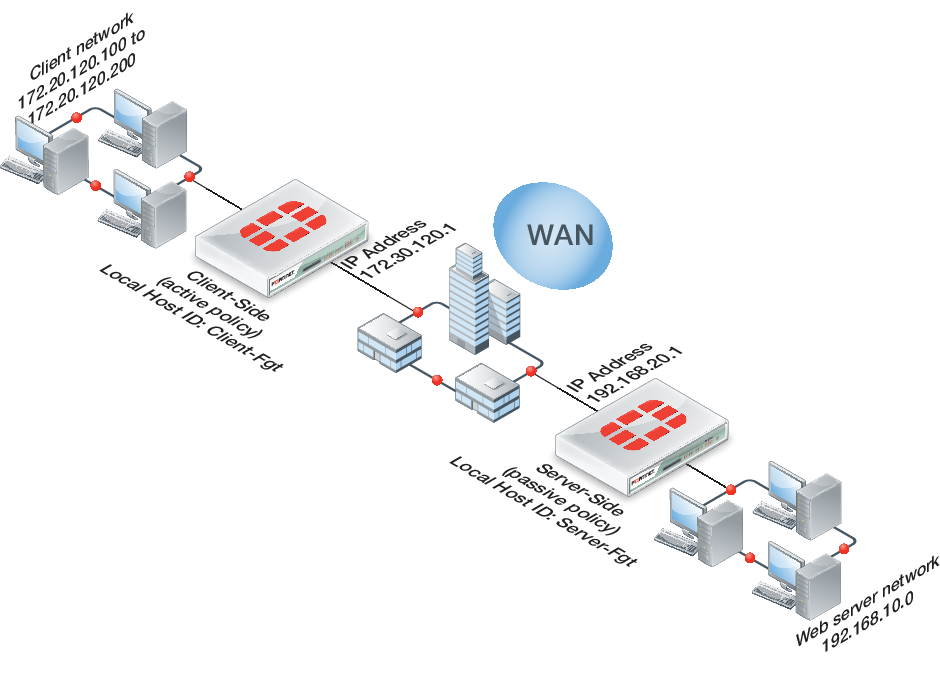
On the client-side FortiGate unit this example configuration includes a WAN optimization profile that optimizes CIFS, HTTP, and FTP traffic and an active WAN optimization policy. The active policy also applies virus scanning to the WAN optimization traffic.
On the server-side FortiGate unit, the passive policy applies application control to the WAN optimization traffic.
In this example, WAN optimization transparent mode is selected in the WAN optimization profile and the passive WAN optimization policy accepts this transparent mode setting. This means that the optimized packets maintain their original source and destination addresses. As a result, routing on the client network must be configured to route packets for the server network to the client-side FortiGate unit. Also the routing configuration on the server network must be able to route packets for the client network to the server-side FortiGate unit.
Example active-passive WAN optimization topology
General configuration steps
This section breaks down the configuration for this example into smaller procedures. For best results, follow the procedures in the order given:
- Configure the client-side FortiGate unit:
- Add peers.
- Add a WAN optimization profile to optimize CIFS, FTP, and HTTP traffic.
- Add firewall addresses for the client and web server networks.
- Add an active WAN optimization policy.
- Configure the server-side FortiGate unit by:
- Add peers.
- Add firewall addresses for the client and web server networks.
- Add a passive WAN optimization policy.
- Add a WAN optimization tunnel policy.
Configuring basic active-passive WAN optimization - web-based manager
Use the following steps to configure the example WAN optimization configuration from the client-side and server-side FortiGate unit web-based manager.
To configure the client-side FortiGate unit
- Go to WAN Opt. & Cache > WAN Opt. Peers > Peers and enter a Local Host ID for the client-side FortiGate unit:
| Local Host ID | Client-Fgt |
- Select Apply.
- Select Create New and add a Peer Host ID and the IP Address for the server-side FortiGate unit:
| Peer Host ID | Server-Fgt |
| IP Address | 192.168.20.1 |
- Select OK.
- Go to WAN Opt. & Cache > WAN Opt. Profiles > Profiles and select Create New to add a WAN optimization profile to optimize CIFS, HTTP, and FTP traffic:
| Name | Custom-wan-opt-pro |
| Transparent Mode | Select |
- Select the CIFS protocol, select Byte Caching and set the Port to 445.
- Select the FTP protocol, select Byte Caching and set the Port to 21.
- Select the HTTP protocol, select Byte Caching and set the Port to 80.
- Select OK.
- Go to Policy & Objects > Objects > Addresses and select Create New to add an address for the client network.
| Category | Address |
| Address Name | Client-Net |
| Type | IP Range |
| Subnet / IP Range | 172.20.120.100-172.20.120.200 |
| Interface | port1 |
- Select Create New to add an address for the web server network.
| Category | Address |
| Address Name | Web-Server-Net |
| Type | Subnet |
| Subnet / IP Range | 192.168.10.0/24 |
| Interface | port2 |
- Go to Policy & Objects > Policy > IPv4 and select Create New to add an active WAN optimization security policy:
| Incoming Interface | port1 |
| Source Address | Client-Net |
| Outgoing Interface | port2 |
| Destination Address | Web-Server-Net |
| Schedule | always |
| Service | HTTP FTP SMB |
| Action | ACCEPT |
- Turn on WAN Optimization and configure the following settings:
| WAN Optimization | active |
| Profile | Custom-wan-opt-pro |
- Turn on Antivirus and select the default antivirus profile.
- Select OK.
To configure the server-side FortiGate unit
- Go to WAN Opt. & Cache > WAN Opt. Peers > Peers and enter a Local Host ID for the server-side FortiGate unit:
| Local Host ID | Server-Fgt |
- Select Apply.
- Select Create New and add a Peer Host ID and the IP Address for the client-side FortiGate unit:
| Peer Host ID | Client-Fgt |
| IP Address | 172.30.120.1 |
- Select OK.
- Go to Policy & Objects > Objects > Addresses and select Create New to add an address for the client network.
| Category | Address |
| Address Name | Client-Net |
| Type | IP Range |
| Subnet / IP Range | 172.20.120.100-172.20.120.200 |
| Interface | port1 |
- Select Create New to add a firewall address for the web server network.
| Category | Address |
| Address Name | Web-Server-Net |
| Type | Subnet |
| Subnet / IP Range | 192.168.10.0/24 |
| Interface | port2 |
- Select OK.
- Select Policy & Objects > Policy > IPv4 and select Create New to add a passive WAN optimization policy that applies application control.
| Incoming Interface | port2 |
| Source Address | Client-Net |
| Outgoing Interface | port1 |
| Destination Address | Web-Server-Net |
| Schedule | always |
| Service | ALL |
| Action | ACCEPT |
- Turn on WAN Optimization and configure the following settings:
| WAN Optimization | passive |
| Passive Option | default |
- Select OK.
- From the CLI enter the following command to add a WAN optimization tunnel explicit proxy policy.
configure firewall explicit-proxy-policy
edit 0
set proxy wanopt
set dstintf port1
set srcaddr all
set dstaddr all
set action accept
set schedule always
set service ALL
next
end
Configuring basic active-passive WAN optimization - CLI
Use the following steps to configure the example WAN optimization configuration from the client-side and server-side FortiGate unit CLI.
To configure the client-side FortiGate unit
- Add the Local Host ID to the client-side FortiGate configuration:
config wanopt settings
set host-id Client-Fgt
end
- Add the server-side Local Host ID to the client-side peer list:
config wanopt peer
edit Server-Fgt
set ip 192.168.20.1
end
- Add a WAN optimization profile to optimize CIFS, HTTP, and FTP traffic.
config wanopt profile
edit Custom-wan-opt-pro
config cifs
set status enable
set byte-caching enable
set port 445
end
config http
set status enable
set byte-caching enable
set port 80
end
config ftp
set status enable
set byte-caching enable
set port 21
end
end
- Add a firewall address for the client network.
config firewall address
edit Client-Net
set type iprange
set start-ip 172.20.120.100
set end-ip 172.20.120.200
set associated-interface port1
end
- Add a firewall address for the web server network.
config firewall address
edit Web-Server-Net
set type ipmask
set subnet 192.168.10.0 255.255.255.0
set associated-interface port2
end
- Add an active WAN optimization security policy that applies virus scanning:
config firewall policy
edit 0
set srcintf port1
set dstintf port2
set srcaddr Client-net
set dstaddr Web-Server-Net
set action accept
set service HTTP FTP SMB
set schedule always
set wanopt enable
set wanopt-detection active
set wanopt-profile Custom-wan-opt-pro
end
To configure the server-side FortiGate unit
- Add the Local Host ID to the server-side FortiGate configuration:
config wanopt settings
set host-id Server-Fgt
end
- Add the client-side Local Host ID to the server-side peer list:
config wanopt peer
edit Client-Fgt
set ip 172.20.120.1
end
- Add a firewall address for the client network.
config firewall address
edit Client-Net
set type iprange
set start-ip 172.20.120.100
set end-ip 172.20.120.200
set associated-interface port1
end
- Add a firewall address for the web server network.
config firewall address
edit Web-Server-Net
set type ipmask
set subnet 192.168.10.0 255.255.255.0
set associated-interface port2
end
- Add a passive WAN optimization policy.
config firewall policy
edit 0
set srcintf port1
set dstintf port2
set srcaddr Client-Net
set dstaddr Web-Server-Net
set action accept
set service ALL
set schedule always
set wanopt enable
set wanopt-detection passive
set wanopt-passive-opt default
end
- Add a WAN optimization tunnel explicit proxy policy.
configure firewall explicit-proxy-policy
edit 0
set proxy wanopt
set dstintf port1
set srcaddr all
set dstaddr all
set action accept
set schedule always
set service ALL
next
end
Testing and troubleshooting the configuration
To test the configuration attempt to start a web browsing session between the client network and the web server network. For example, from a PC on the client network browse to the IP address of a web server on the web server network, for example http://192.168.10.100. Even though this address is not on the client network you should be able to connect to this web server over the WAN optimization tunnel.
If you can connect, check WAN optimization monitoring (go to WAN Opt. & Cache > Monitor > Monitor). If WAN optimization has been forwarding the traffic the WAN optimization monitor should show the protocol that has been optimized (in this case HTTP) and the reduction rate in WAN bandwidth usage.
If you can’t connect you can try the following to diagnose the problem:
- Review your configuration and make sure all details such as address ranges, peer names, and IP addresses are correct.
- Confirm that the security policy on the Client-Side FortiGate unit is accepting traffic for the 192.168.10.0 network and that this security policy does not include security profiles. You can do this by checking the FortiGate session table from the dashboard. Look for sessions that use the policy ID of this policy.
- Check routing on the FortiGate units and on the client and web server networks to make sure packets can be forwarded as required. The FortiGate units must be able to communicate with each other, routing on the client network must allow packets destined for the web server network to be received by the client-side FortiGate unit, and packets from the server-side FortiGate unit must be able to reach the web servers etc.
You can use the following get and diagnose commands to display information about how WAN optimization is operating
Enter the following command to list all of the running WAN optimization tunnels and display information about each one. The command output shows 3 tunnels all created by peer-to-peer WAN optimization rules (auto-detect set to on).
diagnose wad tunnel list
Tunnel: id=139 type=auto
vd=0 shared=no uses=0 state=1
peer name= id=0 ip=unknown
SSL-secured-tunnel=no auth-grp=test
bytes_in=744 bytes_out=76
Tunnel: id=141 type=auto
vd=0 shared=no uses=0 state=1
peer name= id=0 ip=unknown
SSL-secured-tunnel=no auth-grp=test
bytes_in=727 bytes_out=76
Tunnel: id=142 type=auto
vd=0 shared=no uses=0 state=1
peer name= id=0 ip=unknown
SSL-secured-tunnel=no auth-grp=test
bytes_in=727 bytes_out=76
Tunnels total=3 manual=0 auto=3
Example Adding secure tunneling to an active-passive WAN optimization configuration
This example shows how to configure two FortiGate units for active-passive WAN optimization with secure tunneling. The same authentication group is added to both FortiGate units. The authentication group includes a password (or pre-shared key) and has Peer Acceptance set to Accept any Peer. An active policy is added to the client-side FortiGate unit and a passive policy to the server-side FortiGate unit. The active policy includes a profile that performs secure tunneling, optimizes HTTP traffic, and uses Transparent Mode and byte caching.
The authentication group is named Auth-Secure-Tunnel and the password for the pre-shared key is 2345678. The topology for this example is shown below. This example includes web-based manager configuration steps followed by equivalent CLI configuration steps. For information about secure tunneling, see Secure tunneling.
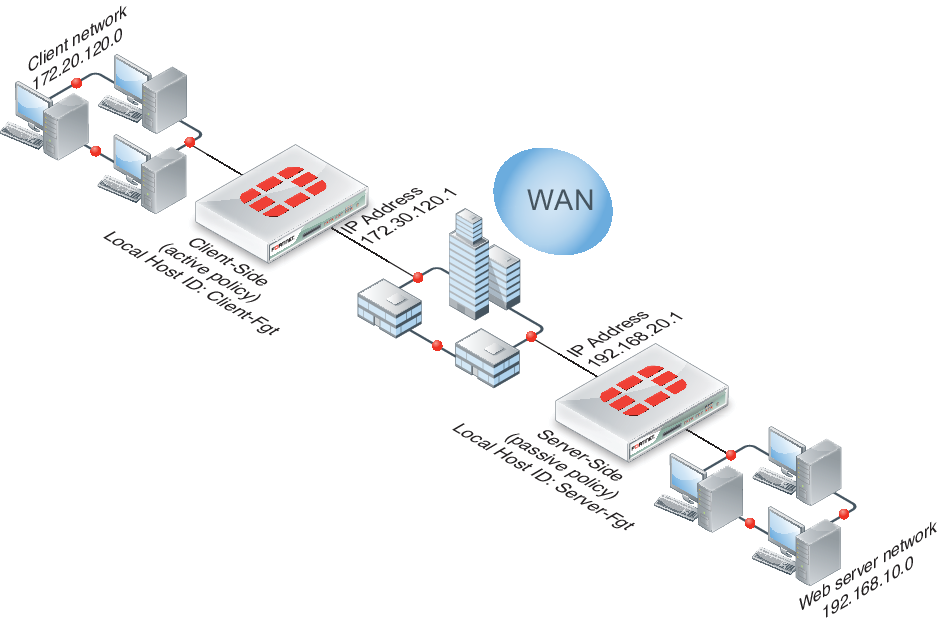
Network topology and assumptions
This example configuration includes a client-side FortiGate unit called Client-net with a WAN IP address of 172.30.120.1.This unit is in front of a network with IP address 172.20.120.0. The server-side FortiGate unit is called Web-servers and has a WAN IP address of 192.168.20.1. This unit is in front of a web server network with IP address 192.168.10.0.
Example active-passive WAN optimization and secure tunneling topology
General configuration steps
This section breaks down the configuration for this example into smaller procedures. For best results, follow the procedures in the order given:
- Configure the client-side FortiGate unit:
- Add peers.
- Add an authentication group.
- Add an active WAN optimization policy.
- Configure the server-side FortiGate unit.
- Add peers.
- Add the same authentication group
- Add a passive WAN optimization policy that applies application control.
- Add a WAN optimization tunnel policy.
Also note that if you perform any additional actions between procedures, your configuration may have different results.
Configuring WAN optimization with secure tunneling - web-based manager
Use the following steps to configure the example WAN optimization configuration from the client-side and server-side FortiGate unit web-based manager. (CLI steps follow.)
To configure the client-side FortiGate unit
- Go to WAN Opt. & Cache > WAN Opt. Peers > Peers and enter a Local Host ID for the client-side FortiGate unit:
| Local Host ID | Client-Fgt |
- Select Apply to save your setting.
- Select Create New and add a Peer Host ID and the IP Address for the server-side FortiGate unit:
| Peer Host ID | Server-Fgt |
| IP Address | 192.168.20.1 |
- Select OK.
- Go to Wan Opt. & Cache > WAN Opt. Peers > Authentication Groups and select Create New to add the authentication group to be used for secure tunneling:
| Name | Auth-Secure-Tunnel |
| Authentication Method | Pre-shared key |
| Password | 2345678 |
| Peer Acceptance | Accept Any Peer |
- Select OK.
- Go to Wan Opt. & Cache > WAN Opt. Profiles > Profiles and select Create New to add a WAN optimization profile that enables secure tunneling and includes the authentication group:
| Name | Secure-wan-op-pro |
| Transparent Mode | Select |
| Authentication Group | Auth-Secure-tunnel |
- Select the HTTP protocol, select Secure Tunneling and Byte Caching and set the Port to 80.
- Select OK.
- Go to Policy & Objects > Objects > Addresses and select Create New to add a firewall address for the client network.
| Category | Address |
| Name | Client-Net |
| Type | Subnet |
| Subnet / IP Range | 172.20.120.0/24 |
| Interface | port1 |
- Select Create New to add a firewall address for the web server network.
| Category | Address |
| Address Name | Web-Server-Net |
| Type | Subnet |
| Subnet / IP Range | 192.168.10.0/24 |
| Interface | port2 |
- Go to Policy & Objects > Policy > IPv4 and select Create New to add an active WAN optimization security policy:
| Incoming Interface | port1 |
| Source Address | Client-Net |
| Outgoing Interface | port2 |
| Destination Address | Web-Server-Net |
| Schedule | always |
| Service | HTTP |
| Action | ACCEPT |
- Turn on WAN Optimization and configure the following settings:
| WAN Optimization | active |
| Profile | Secure-wan-opt-pro |
- Select OK.
To configure the server-side FortiGate unit
- Go to WAN Opt. & Cache > WAN Opt. Peers > Peers and enter a Local Host ID for the server-side FortiGate unit:
| Local Host ID | Server-Fgt |
- Select Apply to save your setting.
- Select Create New and add a Peer Host ID and the IP Address for the client-side FortiGate unit:
| Peer Host ID | Client-Fgt |
| IP Address | 172.30.120.1 |
- Select OK.
- Go to Wan Opt. & Cache > WAN Opt. Peers > Authentication Groups and select Create New and add an authentication group to be used for secure tunneling:
| Name | Auth-Secure-Tunnel |
| Authentication Method | Pre-shared key |
| Password | 2345678 |
| Peer Acceptance | Accept Any Peer |
- Select OK.
- Go to Policy & Objects > Objects > Addresses and select Create New to add a firewall address for the client network.
| Category | Address |
| Name | Client-Net |
| Type | Subnet |
| Subnet / IP Range | 172.20.120.0/24 |
| Interface | port1 |
- Select Create New to add a firewall address for the web server network.
| Category | Address |
| Address Name | Web-Server-Net |
| Type | Subnet |
| Subnet / IP Range | 192.168.10.0/24 |
| Interface | port2 |
- Select OK.
- Select Create New to add a passive WAN optimization policy that applies application control.
| Incoming Interface | port2 |
| Source Address | Client-Net |
| Outgoing Interface | port1 |
| Destination Address | Web-Server-Net |
| Schedule | always |
| Service | ALL |
| Action | ACCEPT |
- Turn on WAN Optimization and configure the following settings:
| WAN Optimization | passive |
| Passive Option | default |
- Select OK.
- From the CLI enter the following command to add a WAN optimization tunnel explicit proxy policy.
configure firewall explicit-proxy-policy
edit 0
set proxy wanopt
set dstintf port1
set srcaddr all
set dstaddr all
set action accept
set schedule always
set service ALL
next
end
Configuring WAN optimization with secure tunneling - CLI
Use the following steps to configure the example WAN optimization configuration from the client-side and server-side FortiGate unit CLI.
To the client-side FortiGate unit
- Add the Local Host ID to the client-side FortiGate configuration:
config wanopt settings
set host-id Client-Fgt
end
- Add the server-side Local Host ID to the client-side peer list:
config wanopt peer
edit Server-Fgt
set ip 192.168.20.1
end
- Add a new authentication group to be used for secure tunneling:
config wanopt auth-group
edit Auth-Secure-Tunnel
set auth-method psk
set psk 2345678
end
Leave
peer-acceptat its default value.
- Add a WAN optimization profile that enables secure tunneling and includes the authentication group, enables HTTP protocol optimization, and enables secure tunneling and byte caching for HTTP traffic:
config wanopt profile
edit Secure-wan-op-pro
set auth-group Auth-Secure-Tunnel
config http
set status enable
set secure-tunnel enable
set byte-caching enable
set port 80
end
end
- Add a firewall address for the client network.
config firewall address
edit Client-Net
set type ipmask
set subnet 172.20.120.0 255.255.255.0
set associated-interface port1
end
- Add a firewall address for the web server network.
config firewall address
edit Web-Server-Net
set type ipmask
set subnet 192.168.10.0 255.255.255.0
set associated-interface port2
end
- Add an active WAN optimization security policy that includes the WAN optimization profile that enables secure tunneling and that applies virus scanning:
config firewall policy
edit 0
set srcintf port1
set dstintf port2
set srcaddr Client-Net
set dstaddr Web-Server-Net
set action accept
set service HTTP
set schedule always
set wanopt enable
set wanopt-detection active
set wanopt-profile Secure-wan-opt-pro
end
To configure the server-side FortiGate unit
- Add the Local Host ID to the server-side FortiGate configuration:
config wanopt settings
set host-id Server-Fgt
end
- Add the client-side Local Host ID to the server-side peer list:
config wanopt peer
edit Client-Fgt
set ip 172.20.120.1
end
- Add an authentication group to be used for secure tunneling:
config wanopt auth-group
edit Auth-Secure-Tunnel
set auth-method psk
set psk 2345678
end
Leave
peer-acceptat its default value.
- Add a firewall address for the client network.
config firewall address
edit Client-Net
set type ipmask
set subnet 172.20.120.0 255.255.255.0
set associated-interface port1
end
- Add a firewall address for the web server network.
config firewall address
edit Web-Server-Net
set type ipmask
set subnet 192.168.10.0 255.255.255.0
set associated-interface port2
end
- Add a passive WAN optimization policy.
config firewall policy
edit 0
set srcintf port1
set dstintf port2
set srcaddr Client-Net
set dstaddr Web-Server-Net
set action accept
set service ALL
set schedule always
set wanopt enable
set wanopt-detection passive
set wanopt-passive-opt default
end
- Add a WAN optimization tunnel explicit proxy policy.
configure firewall explicit-proxy-policy
edit 0
set proxy wanopt
set dstintf port1
set srcaddr all
set dstaddr all
set action accept
set schedule always
set service ALL
next
end
Copyright © 2018 Fortinet, Inc. All Rights Reserved. | Terms of Service | Privacy Policy
