Home > Online Help
Partially-redundant route-based VPN example
This example demonstrates how to set up a partially redundant IPsec VPN between a local FortiGate unit and a remote VPN peer that receives a dynamic IP address from an ISP before it connects to the FortiGate unit. For more information about FortiGate dialup-client configurations, see FortiGate dialup-client configurations .
When a FortiGate unit has more than one interface to the Internet (see FortiGate_1), you can configure redundant routes. If the primary connection fails, the FortiGate unit can establish a VPN using the redundant connection.
In this case, FortiGate_2 has only one connection to the Internet. If the link to the ISP were to go down, the connection to FortiGate_1 would be lost, and the tunnel would be taken down. The tunnel is said to be partially redundant because FortiGate_2 does not support a redundant connection.
In the configuration example:
- Both FortiGate units operate in NAT mode.
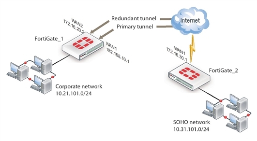
- Two separate interfaces to the Internet (192.168.10.2 and 172.16.20.2) are available on FortiGate_1. Each interface has a static public IP address.
- FortiGate_2 has a single connection to the Internet and obtains a dynamic public IP address (for example, 172.16.30.1) when it connects to the Internet.
- FortiGate_2 forwards IP packets from the SOHO network (10.31.101.0/24) to the corporate network (10.21.101.0/24) behind FortiGate_1 through a partially redundant IPsec VPN. Encrypted packets from FortiGate_2 are addressed to the public interface of FortiGate_1. Encrypted packets from FortiGate_1 are addressed to the public IP address of FortiGate_2.
There are two possible paths for communication between the two units. In this example, these paths, listed in descending priority, are:
- FortiGate_1 WAN 1 to FortiGate_2 WAN 1
- FortiGate_1 WAN 2 to FortiGate_2 WAN 1
For each path, VPN configuration, security policies and routing are defined. By specifying a different routing distance for each path, the paths are prioritized. A VPN tunnel is established on each path, but only the highest priority one is used. If the highest priority path goes down, the traffic is automatically routed over the next highest priority path. You could use dynamic routing, but to keep this example simple, static routing is used.
Example partially redundant route-based configuration
Configuring FortiGate_1
Whenconfiguring FortiGate_1, you must:
- Configure the interfaces involved in the VPN.
- Define the Phase 1 configuration for each of the two possible paths, creating a virtual IPsec interface for each one.
- Define the Phase 2 configuration for each of the two possible paths.
- Configure incoming and outgoing security policies between the internal interface and each of the virtual IPsec interfaces.
To configure the network interfaces
- Go to System > Network > Interfaces.
- Select the Internal interface and select Edit. Enter the following information and select OK:
| Addressing mode |
Manual |
| IP/Netmask |
10.21.101.2/255.255.255.0
|
- Select the WAN1 interface and select Edit. Enter the following information and select OK:
| Addressing mode |
Manual |
| IP/Netmask |
192.168.10.2/255.255.255.0
|
- Select the WAN2 interface and select Edit. Enter the following information and select OK:
| Addressing mode |
Manual |
| IP/Netmask |
172.16.20.2/255.255.255.0
|
To configure the IPsec interfaces (Phase 1 configurations)
- Go to VPN > IPsec > Tunnels and create the new custom tunnel or edit an existing tunnel.
- Edit the Phase 1 Proposal (if it is not available, you may need to click the Convert to Custom Tunnel button).
- Enter the following information, and select OK:
| Name |
Site_1_A
|
| Remote Gateway |
Dialup User |
| Local Interface |
WAN1 |
| Mode |
Main |
| Authentication Method |
Preshared Key |
| Pre-shared Key |
Enter the preshared key. |
| Peer Options |
Any peer ID |
| Advanced |
|
| Dead Peer Detection |
Select |
- Create a new tunnel and enter the following Phase 1 information:
| Name |
Site_1_B
|
| Remote Gateway |
Dialup User |
| Local Interface |
WAN2 |
| Mode |
Main |
| Authentication Method |
Preshared Key |
| Pre-shared Key |
Enter the preshared key. |
| Peer Options |
Any peer ID |
| Advanced |
|
| Dead Peer Detection |
Select |
To define the Phase 2 configurations for the two VPNs
- Open the Phase 2 Selectors panel.
- Enter the following information and select OK:
| Name |
Route_A
|
| Phase 1 |
Site_1_A
|
- Enter the following Phase 2 information for the subsequent route:
| Name |
Route_B
|
| Phase 1 |
Site_1_B
|
To configure routes
- Go to Router > Static > Static Routes.
- For low-end FortiGate units, go to System > Network > Routing.
- Select Create New, enter the following default gateway information and select OK:
| Destination IP/Mask |
0.0.0.0/0.0.0.0
|
| Device |
WAN1 |
| Gateway |
192.168.10.1
|
| Distance (Advanced) |
10 |
To configure security policies
- Go to Policy & Objects > Policy > IPv4 and select Create New.
- Enter the following information, and select OK:
| Incoming Interface |
Internal |
| Source Address |
All |
| Outgoing Interface |
Site_1_A |
| Destination Address |
All |
| Schedule |
Always |
| Service |
Any |
| Action |
ACCEPT |
- Select Create New.
- Enter the following information, and select OK:
| Incoming Interface |
Internal |
| Source Address |
All |
| Outgoing Interface |
Site_1_B |
| Destination Address |
All |
| Schedule |
Always |
| Service |
Any |
| Action |
ACCEPT |
Configuring FortiGate_2
The configuration for FortiGate_2 is similar to that of FortiGate_1. You must
- configure the interface involved in the VPN
- define the Phase 1 configuration for the primary and redundant paths, creating a virtual IPsec interface for each one
- define the Phase 2 configurations for the primary and redundant paths, defining the internal network as the source address so that FortiGate_1 can automatically configure routing
- configure the routes for the two IPsec interfaces, assigning the appropriate priorities
- configure security policies between the internal interface and each of the virtual IPsec interfaces
To configure the network interfaces
- Go to System > Network > Interfaces.
- Select the Internal interface and select Edit. Enter the following information and select OK:
| Addressing mode |
Manual |
| IP/Netmask |
10.31.101.2/255.255.255.0
|
- Select the WAN1 interface and select Edit. Set the Addressing mode to DHCP.
To configure the two IPsec interfaces (Phase 1 configurations)
- Go to VPN > IPsec > Tunnels and create the new custom tunnel or edit an existing tunnel.
- Edit the Phase 1 Proposal (if it is not available, you may need to click the Convert to Custom Tunnel button).
- Enter the following information, and select OK:
| Name |
Site_2_A
|
| Remote Gateway |
Static IP Address |
| IP Address |
192.168.10.2
|
| Local Interface |
WAN1 |
| Mode |
Main |
| Authentication Method |
Preshared Key |
| Pre-shared Key |
Enter the preshared key. |
| Peer Options |
Any peer ID |
| Advanced |
|
| Dead Peer Detection |
Select |
- Create a new tunnel and enter the following Phase 1 information:
| Name |
Site_2_B
|
| Remote Gateway |
Static IP Address |
| IP Address |
172.16.20.2
|
| Local Interface |
WAN1 |
| Mode |
Main |
| Authentication Method |
Preshared Key |
| Pre-shared Key |
Enter the preshared key. |
| Peer Options |
Any peer ID |
| Advanced |
|
| Dead Peer Detection |
Select |
To define the Phase 2 configurations for the two VPNs
- Open the Phase 2 Selectors panel.
- Enter the following information and select OK:
| Name |
Route_A
|
| Phase 1 |
Site_2_A
|
| Advanced |
|
| Source Address |
10.31.101.0/24 |
- Enter the following Phase 2 information for the subsequent route:
| Name |
Route_B
|
| Phase 1 |
Site_2_B
|
| Advanced |
|
| Source Address |
10.31.101.0/24 |
To configure routes
- Go to Router > Static > Static Routes.
For low-end FortiGate units, go to System > Network > Routing.
- Select Create New, enter the following information and then select OK:
| Destination IP/Mask |
10.21.101.0/255.255.255.0
|
| Device |
Site_2_A |
| Distance (Advanced) |
1 |
- Select Create New, enter the following information and then select OK:
| Destination IP/Mask |
10.21.101.0/255.255.255.0
|
| Device |
Site_2_B |
| Distance (Advanced) |
2 |
To configure security policies
- Go to Policy & Objects > Policy > IPv4 and select Create New.
- Enter the following information, and select OK:
| Incoming Interface |
Internal |
| Source Address |
All |
| Outgoing Interface |
Site_2_A |
| Destination Address |
All |
| Schedule |
Always |
| Service |
Any |
| Action |
ACCEPT |
- Select Create New.
- Enter the following information, and select OK:
| Incoming Interface |
Internal |
| Source Address |
All |
| Outgoing Interface |
Site_2_B |
| Destination Address |
All |
| Schedule |
Always |
| Service |
Any |
| Action |
ACCEPT |

