
Basic OSPF example
This example sets up an OSPF network at a small office. There are 3 routers, all running OSPF v2. The border router connects to a BGP network.
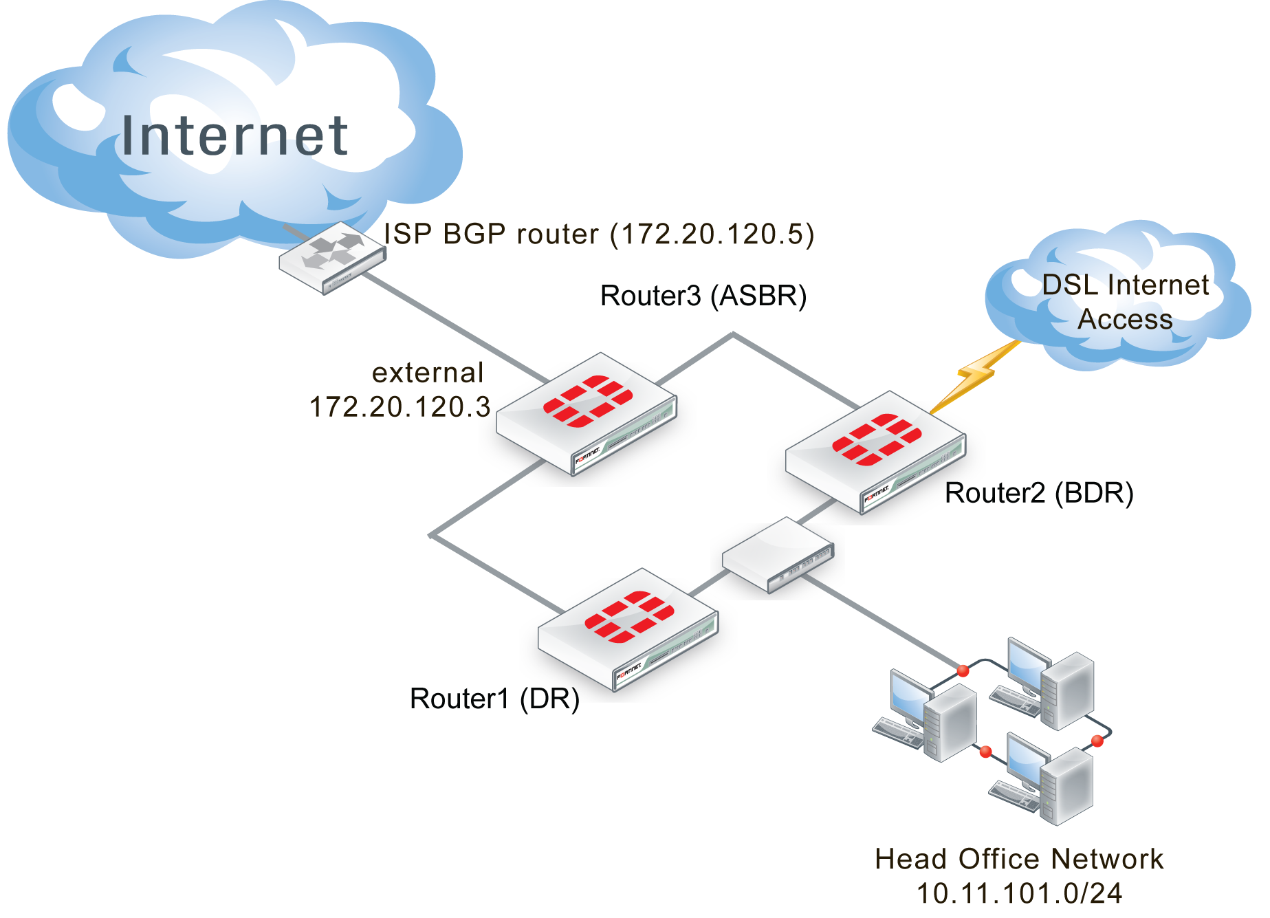
All three routers in this example are FortiGate units. Router1 will be the designated router (DR) and router2 will be the backup DR (BDR) due to their priorities. Router3 will not be considered for either the DR or BDR elections. Instead, Router3 is the area border router (ASBR) routing all traffic to the ISP’s BGP router on its way to the Internet.
Router2 has a modem connected that provides dialup access to the Internet as well, at a reduced bandwidth. This is a PPPoE connection to a DSL modem. This provides an alternate route to the Internet if the other route goes down. The DSL connection is slow, and is charged by the amount of traffic. For these reasons OSPF will highly favor Router3’s Internet access.
The DSL connection connects to an OSPF network with the ISP, so no redistribution of routes is required. The ISP network does have to be added to that router’s configuration however.
This section includes the following topics:
- Network layout and assumptions
- Configuring the FortiGate units
- Configuring OSPF on the FortiGate units
- Configuring other networking devices
- Testing network configuration
Network layout and assumptions
There are three FortiGate units acting as OSPF v2 routers on the network—Router1, Router2, and Router3. Router1 will be the designated router (DR), and Router 2 the BDR. Router3 is the area border router (ASBR) that connects to the external ISP router running BGP. Router2 has a PPPoE DSL connection that can access the Internet.
The Head Office network is connected to Router1 and Router2 on the 10.11.101.0 subnet.
Router1 and Router3 are connected over the 10.11.103.0 subnet.
Router2 and Router3 are connected over the 10.11.102.0 subnet.
The following table lists the router, interface, address, and role it is assigned.
Routers, interfaces, and IP addresses for basic OSPF example network
| Router name | Interface | IP address | Interface is connected to: |
|---|---|---|---|
| Router1 (DR) | Internal (port1) | 10.11.101.1 | Head office network, and Router2 |
| External (port2) | 10.11.102.1 | Router3 | |
| Router2 (BDR) | Internal (port1) | 10.11.101.2 | Head office network, and Router1 |
| External (port2) | 10.11.103.2 | Router3 | |
| DSL (port3) | 10.12.101.2 | PPPoE DSL access | |
| Router3 (ASBR) | Internal1 (port1) | 10.11.102.3 | Router1 |
| Internal2 (port2) | 10.11.103.3 | Router2 | |
| External (port3) | 172.20.120.3 | ISP’s BGP network |
Basic OSPF network topology
Note that other subnets can be added to the internal interfaces without changing the configuration.
Assumptions
- The FortiGate units used in this example have interfaces named port1, port2, and port3.
- All FortiGate units in this example have factory default configuration with FortiOS 5.2 firmware installed, and are in NAT/Route operation mode.
- Basic firewalls are in place to allow unfiltered traffic between all connected interfaces in both directions.
- This OSPF network is not connected to any other OSPF networks.
- Both Internet connections are always available.
- The modem connection is very slow and expensive.
- Other devices may be on the network, but do not affect this basic configuration.
- Router3 is responsible for redistributing all routes into and out of the OSPF AS.
Configuring the FortiGate units
Each FortiGate unit needs the interfaces, and basic system information such as hostname configured.
This section includes:
Configuring Router1
Router1 has two interfaces connected to the network—internal (port1) and external (port2). Its host name must be changed to Router1.
To configure Router1 interfaces - web-based manager
- Go to System > Dashboard > Status.
- Beside the host name, select Change.
- Enter a hostname of
Router1, and select OK. - Go to System > Network > Interfaces, edit port1, set the following information, and select OK.
| Alias | internal |
| IP/Network Mask | 10.11.101.1/255.255.255.0 |
| Administrative Access | HTTPS SSH PING |
| Description | Head office and Router2 |
| Administrative Status | Up |
- Edit port2, set the following information, and select OK.
| Alias | External |
| IP/Network Mask | 10.11.102.1/255.255.255.0 |
| Administrative Access | HTTPS SSH PING |
| Description | Router3 |
| Administrative Status | Up |
Configuring Router2
Router2 configuration is the same as Router1, except Router2 also has the DSL interface to configure.
The DSL interface is configured with a username of “user1” and a password of “ospf_example”. The default gateway will be retrieved from the ISP, and the defaults will be used for the rest of the PPPoE settings.
To configure Router2 interfaces - web-based manager
- Go to System > Dashboard > Status.
- Beside the host name, select Change.
- Enter a hostname of
Router2, and select OK. - Go to System > Network > Interfaces, edit port1, set the following information, and select OK.
| Alias | internal |
| IP/Network Mask | 10.11.101.2/255.255.255.0 |
| Administrative Access | HTTPS SSH PING |
| Description | Head office and Router1 |
| Administrative Status | Up |
- Edit port2, set the following information, and select OK.
| Alias | External |
| IP/Network Mask | 10.11.103.2/255.255.255.0 |
| Administrative Access | HTTPS SSH PING |
| Description | Router3 |
| Administrative Status | Up |
- Edit DSL (port3), set the following information, and select OK.
| Alias | DSL |
| Addressing Mode | PPPoE |
| Username | user1 |
| Password | ospf_example |
| Unnumbered IP | 10.12.101.2/255.255.255.0 |
| Retrieve default gateway from server | Enable |
| Administrative Access | HTTPS SSH PING |
| Description | DSL |
| Administrative Status | Up |
Configuring Router3
Router3 is similar to Router1 and Router2 configurations. The main difference is the External (port3) interface connected to the ISP BGP network which has no administration access enabled for security reasons.
To configure Router3 interfaces - web-based manager
- Go to System > Status > Dashboard.
- Next to hostname, select Change.
- Enter a hostname of
Router3, and select OK. - Go to System > Network > Interfaces, edit port1, set the following information, and select OK.
| Alias | internal |
| IP/Network Mask | 10.11.102.3/255.255.255.0 |
| Administrative Access | HTTPS SSH PING |
| Description | Router1 |
| Administrative Status | Up |
- Edit port2, set the following information, and select OK.
| Alias | Internal2 |
| IP/Network Mask | 10.11.103.3/255.255.255.0 |
| Administrative Access | HTTPS SSH PING |
| Description | Router2 |
| Administrative Status | Up |
- Edit port3, set the following information, and select OK.
| Alias | External |
| IP/Network Mask | 172.20.120.3/255.255.255.0 |
| Administrative Access | HTTPS SSH PING |
| Description | ISP BGP |
| Administrative Status | Up |
Configuring OSPF on the FortiGate units
With the interfaces configured, now the FortiGate units can be configured for OSPF on those interfaces. All routers are part of the backbone 0.0.0.0 area, so there is no inter‑area communications needed.
For a simple configuration there will be no authentication, no graceful restart or other advanced features, and timers will be left at their defaults. Also the costs for all interfaces will be left at 10, except for the modem and ISP interfaces where cost will be used to load balance traffic. Nearly all advanced features of OSPF are only available from the CLI.
The network that is defined covers all the subnets used in this example - 10.11.101.0, 10.11.102.0, and 10.11.103.0. All routes for these subnets will be advertised. If there are other interfaces on the FortiGate units that you do not want included in the OSPF routes, ensure those interfaces use a different subnet outside of the 10.11.0.0 network. If you want all interfaces to be advertised you can use an OSPF network of 0.0.0.0 .
Each router will configure:
- Router ID
- Area
- Network
- Two or three interfaces depending on the router
- Priority for DR (Router1) and BDR (Router2)
- Redistribute for ASBR (Router3)
This section includes:
Configuring OSPF on Router1
Router1 has a very high priority to ensure it becomes the DR for this area. Also Router1 has the lowest IP address to help ensure it will win in case there is a tie at some point. Otherwise it is a standard OSPF configuration. Setting the priority can only be done in the CLI, and it is for a specific OSPF interface.
To configure OSPF on Router1 - web-based manager
- Go to Router > Dynamic > OSPF.
- Set Router ID to
10.11.101.1and select Apply. - In Areas, select Create New, set the following information, and select OK.
| Area | 0.0.0.0 |
| Type | Regular |
| Authentication | none |
- In Networks, select Create New, set the following information, and select OK.
| IP/Netmask | 10.11.0.0/255.255.0.0 |
| Area | 0.0.0.0 |
- In Interfaces, select Create New, set the following information, and select OK.
| Name | Router1-Internal-DR | |
| Interface | port1 (Internal) | |
| IP | 0.0.0.0 | |
| Authentication | none | |
| Timers (seconds) | ||
| Hello Interval | 10 | |
| Dead Interval | 40 | |
- In Interfaces, select Create New, set the following information, and select OK.
| Name | Router1-External | |
| Interface | port2 (External) | |
| IP | 0.0.0.0 | |
| Authentication | none | |
| Timers (seconds) | ||
| Hello Interval | 10 | |
| Dead Interval | 40 | |
- Using the CLI, enter the following commands to set the priority for the Router1‑Internal OSPF interface to maximum, ensuring this interface becomes the DR.
config router ospf
config ospf-interface
edit Router1-Internal-DR
set priority 255
end
To configure OSPF on Router1 - CLI
config router ospf
set router-id 10.11.101.1
config area
edit 0.0.0.0
next
end
config network
edit 1
set prefix 10.11.0.0/255.255.255.0
next
end
config ospf-interface
edit "Router1-Internal"
set interface "port1"
set priority 255
next
edit "Router1-External"
set interface "port2"
next
end
end
Configuring OSPF on Router2
Router2 has a high priority to ensure it becomes the BDR for this area, and configures the DSL interface slightly differently—assume this will be a slower connection resulting in the need for longer timers, and a higher cost for this route.
Otherwise it is a standard OSPF configuration.
To configure OSPF on Router2 - web-based manager
- Go to Router > Dynamic > OSPF.
- Set Router ID to
10.11.101.2and select Apply. - In Areas, select Create New, set the following information, and select OK.
| Area | 0.0.0.0 |
| Type | Regular |
| Authentication | none |
- In Networks, select Create New, set the following information, and select OK.
| IP/Netmask | 10.11.0.0/255.255.0.0 |
| Area | 0.0.0.0 |
- In Interfaces, select Create New, set the following information, and select OK.
| Name | Router2-Internal | |
| Interface | port1 (Internal) | |
| IP | 0.0.0.0 | |
| Authentication | none | |
| Timers (seconds) | ||
| Hello Interval | 10 | |
| Dead Interval | 40 | |
- In Interfaces, select Create New, set the following information, and select OK.
| Name | Router2-External | |
| Interface | port2 (External) | |
| IP | 0.0.0.0 | |
| Authentication | none | |
| Timers (seconds) | ||
| Hello Interval | 10 | |
| Dead Interval | 40 | |
- In Interfaces, select Create New, set the following information, and select OK.
| Name | Router2-DSL | |
| Interface | port3 (DSL) | |
| IP | 0.0.0.0 | |
| Authentication | none | |
| Cost | 50 | |
| Timers (seconds) | ||
| Hello Interval | 20 | |
| Dead Interval | 80 | |
- Using the CLI, enter the following commands to set the priority for the Router2‑Internal OSPF interface to ensure this interface will become the BDR:
config router ospf
config ospf-interface
edit Router2-Internal
set priority 250
next
end
To configure OSPF on Router2 - CLI
config router ospf
set router-id 10.11.101.2
config area
edit 0.0.0.0
next
end
config network
edit 1
set prefix 10.11.0.0/255.255.0.0
next
end
config ospf-interface
edit "Router2-Internal"
set interface "port1"
set priority 255
next
edit "Router2-External"
set interface "port2"
next
edit "Router2-DSL"
set interface "port3"
set cost 50
next
end
end
Configuring OSPF on Router3
Router3 is more complex than the other two routers. The interfaces are straightforward, but this router has to import and export routes between OSPF and BGP. That requirement makes Router3 a border router or ASBR. Also Router3 needs a lower cost on its route to encourage all traffic to the Internet to route through it.
In the advanced OSPF options, Redistribute is enabled for Router3. It allows different types of routes, learned outside of OSPF, to be used in OSPF. Different metrics are assigned to these other types of routes to make them more or less preferred to regular OSPF routes.
To configure OSPF on Router3 - web-based manager
- Go to Router > Dynamic > OSPF.
- Set Router ID to
10.11.101.2and select Apply. - Expand Advanced Options.
- In Redistribute, set the following information, and select OK.
| Route type | Redistribute | Metric |
|---|---|---|
| Connected | Enable | 15 |
| Static | Enable | 15 |
| RIP | Disable | n/a |
| BGP | Enable | 5 |
- In Areas, select Create New, set the following information, and select OK.
| Area | 0.0.0.0 |
| Type | Regular |
| Authentication | none |
- In Networks, select Create New, set the following information, and select OK.
| IP/Netmask | 10.11.0.0/255.255.0.0 |
| Area | 0.0.0.0 |
- In Interfaces, select Create New, set the following information, and select OK.
| Name | Router3-Internal | |
| Interface | port1 (Internal) | |
| IP | 0.0.0.0 | |
| Authentication | none | |
| Timers (seconds) | ||
| Hello Interval | 10 | |
| Dead Interval | 40 | |
- In Interfaces, select Create New, set the following information, and select OK.
| Name | Router3-Internal2 | |
| Interface | port2 (Internal2) | |
| IP | 0.0.0.0 | |
| Authentication | none | |
| Timers (seconds) | ||
| Hello Interval | 10 | |
| Dead Interval | 40 | |
- In Interfaces, select Create New, set the following information, and select OK.
| Name | Router3-ISP-BGP | |
| Interface | port3 (ISP-BGP) | |
| IP | 0.0.0.0 | |
| Authentication | none | |
| Cost | 2 | |
| Timers (seconds) | ||
| Hello Interval | 20 | |
| Dead Interval | 80 | |
- Using the CLI, enter the following commands to set the priority for the Router3‑Internal OSPF interface to ensure this interface will become the BDR.
config router ospf
config ospf-interface
edit Router3-Internal
set priority 250
next
end
To configure OSPF on Router3 - CLI
config router ospf
set router-id 10.11.102.3
config area
edit 0.0.0.0
next
end
config network
edit 1
set prefix 10.11.0.0/255.255.255.0
next
edit 2
set prefix 172.20.120.0/255.255.255.0
next
end
config ospf-interface
edit "Router3-Internal"
set interface "port1"
set priority 255
next
edit "Router3-External"
set interface "port2"
next
edit “Router3-ISP-BGP”
set interface “port3”
set cost 2
next
end
end
Configuring other networking devices
The other networking devices required in this configuration are on the two ISP networks, the BGP network for the main Internet connection, and the DSL backup connection.
In both cases, the ISPs need to be notified of the OSPF network settings including router IP addresses, timer settings, and so on. The ISP will use this information to configure its routers that connect to this OSPF network.
Testing network configuration
Testing the network configuration involves two parts: testing the network connectivity, and testing the OSPF routing.
To test the network connectivity use ping, traceroute, and other network tools.
To test the OSPF routing in this example, refer to the troubleshooting outlined in Basic OSPF example.
Copyright © 2018 Fortinet, Inc. All Rights Reserved. | Terms of Service | Privacy Policy
