
Overview of FortiOS Carrier features
FortiOS Carrier specific features include Multimedia messaging service (MMS) protection, and GPRS Tunneling Protocol (GTP) protection.
All FortiGate units, carrier-enabled or not, are capable of handling Stream Control Transmission Protocol (SCTP) traffic, which is a protocol designed for and primarily used in Carrier networks.
This section includes:
Overview
FortiOS Carrier provides all the features found on FortiGate units plus added features specific to carrier networks: MMS and GTP.
MMS
MMS is a standard for sending messages that include multimedia content between mobile phones. MMS is also popular as a method of delivering news and entertainment content including videos, pictures, and text. Carrier networks include four different MMS types of messages — MM1, MM3, MM4, and MM7. See “MMS background”.
GTP
The GPRS Tunneling Protocol (GTP) runs on GPRS carrier networks. GPRS is a GSM packet radio standard. It provides more efficient usage of the radio interface so that mobile devices can share the same radio channel. FortiOS supports GTPv1 and GTPv2.
GPRS provides direct connections to the Internet (TCP/IP) and X.25 networks for point-to-point services (connection-less/connection oriented) and point-to-multipoint services (broadcast).
GPRS currently supports data rates from 9.6 kbps to more than 100 kbps, and it is best suited for burst forms of traffic. GPRS involves both radio and wired components. The mobile phone sends the message to a base station unit (radio based) that converts the message from radio to wired, and sends the message to the carrier network and eventually the Internet (wired carrier network). See GTP.
Registering FortiOS Carrier
A license is purchased from Fortinet, and is delivered by mail as a scratch card. The contained registration code is entered into the CLI according to the instructions on the card. The FortiGate unit will then factory reset itself into Carrier mode.
Only certain FortiGate models support Carrier mode. Contact Fortinet Support for more information and firmware images.
MMS background
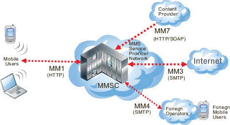
MMS is a common method for mobile users to send and receive multimedia content. A Carrier network supports MMS across its network. This makes up the MMS Service Provider Network (MSPN).
Messages can be sent or received between the MMSC and a number of other services including the Internet, content providers, or other carriers. Each of these different service connections uses different MMS formats including MM1 and MM7 messages (essentially HTTP format), and MM3 and MM4 messages (SMTP formatted). These different formats reflect the different purposes and content for each type of MMS message.
MMS content interfaces
MMS content interfaces
MMS messages are sent from devices and servers to other devices and servers using MMS content interfaces
There are eight interfaces defined for the MMS standard, referred to as MM1 through MM8. The most important of these interfaces for the transfer of data is the MM1 interface, as this defines how mobile users communicate from the mobile network to the Multimedia Message Service Center (MMSC). MMS content to be monitored and controlled comes from these mobile users and is going to the provider network.
Other MMS content interfaces that connect a service provider network to other external sources can pose threats as well. MM3 handles communication between the Internet and the MMSC and is a possible source of viruses and other content problems from the Internet. MM4 handles communication between different content provider MMSCs. Filtering MM4 content protects the service provider network from content sent from foriegn service providers and their subscribers. Finally MM7 is used for communication between content providers and the MMSC. Filtering MM3 content can also keep harmful content off of the service provider network.
MMS content interfaces
| Type | Transaction | Similar to |
|---|---|---|
| MM 1 | Handset to MMSC | HTTP |
| MM 3 | Between MMSC and Internet | SMTP |
| MM 4 | Between Operator MMSCs | SMTP |
| MM 7 | Content Providers to MMSC | HTTP and SOAP |
How MMS content interfaces are applied
As shownbelow, the sender’s mobile device encodes the MMS content in a form similar to MIME email message (MMS MIME content formats are defined by the MMS Message Encapsulation specification). The encoded message is then forwarded to the service provider’s MMSC. Communication between the sending device and the MMSC uses the MM1 content interface. The MM1 content interface establishes a connection and sends an MM1 send request (m‑send.req) message that contains the MMS message. The MMSC processes this request and sends back an MM1 send confirmation (m-send.conf) HTTP response indicating the status of the message — accepted or an error occurred, for example.
MM1 transactions between senders and receivers and the MMSC
![]()
If the recipient is on another carrier, the MMSC forwards the message to the recipient's carrier. This forwarding uses the MM4 content interface for forwarding content between operator MMSCs (see the figure below).
Before the MMSC can forward the message to the final recipient, it must first determine if the receiver’s handset can receive MMS messages using the MM1 content interface. If the recipient can use the MM1 content interface, the content is extracted and sent to a temporary storage server with an HTTP front-end.
To retrieve the message, the receiver’s handset establishes a connection with the MMSC. An HTTP get request is then sent from the recipient to the MMSC. This message contains the URL where the content of the message is stored. The MMSC responds with a retrieve confirmation (m-retrieve.conf) HTTP response that contains the message.
MM4 messages sent between operator MMSCs
![]()
This causes the receiver’s handset to retrieve the content from the embedded URL. Several messages are exchanged to indicate status of the delivery attempt. Before delivering content, some MMSCs also include a content adaptation service that attempts to modify the multimedia content into a format suitable for the recipient’s handset.
If the receiver’s handset is not MM1 capable, the message can be delivered to a web based service and the receiver can view the content from a normal Internet browser. The URL for the content can be sent to the receiver in an SMS text message. Using this method, non-MM1 capable recipients can still receive MMS content.
The method for determining whether a handset is MMS capable is not specified by the standards. A database is usually maintained by the operator, and in it each mobile phone number is marked as being associated with a legacy handset or not. It can be a bit hit and miss since customers can change their handset at will and this database is not usually updated dynamically.
Email and web-based gateways from MMSC to the Internet use the MM3 content interface. On the receiving side, the content servers can typically receive service requests both from WAP and normal HTTP browsers, so delivery via the web is simple. For sending from external sources to handsets, most carriers allow MIME encoded message to be sent to the receiver's phone number with a special domain.
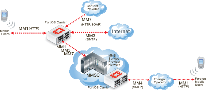
How FortiOS Carrier processes MMS messages
MMS messages can be vectors for propagating undesirable content such as spam and viruses. FortiOS Carrier can scan MMS messages sent using the MM1, MM3, MM4, and MM7 content interfaces. You can configure FortiOS Carrier to scan MMS messages for spam and viruses by configuring and adding MMS protection profiles and adding the MMS protection profiles to security policies. You can also use MMS protection profiles to apply content blocking, carrier endpoint filtering, MMS address translation, sending MMS notifications, DLP archiving of MMS messages, and logging of MMS message activity.
FortiOS Carrier MMS processing
FortiOS Carrier can send MMS messages to senders informing those senders that their devices are infected. FortiOS Carrier can also send MMS notifications to administrators to inform them of suspicious activity on their networks.
For message floods and duplicate messages, FortiOS Carrier does not send notifications to message senders but does send notifications to administrators and sends messages to sender handsets to complete MM1 and MM4 sessions.
Where MMS messaging uses the TCP/IP set of protocols, SMS text messaging uses the Signaling System Number 7 (SS7) set of protocols, which is not supported by FortiOS.
FortiOS Carrier and MMS content scanning
The following section applies to MMS content scanning, including virus scanning, file filtering, content spam filtering, carrier endpoint filtering, and MMS content checksum filtering.
MM1 Content Scanning
During MM1 content scanning a message is first transmitted from the sender, establishing a connection with the MMSC. FortiOS Carrier intercepts this connection and acts as the endpoint. FortiOS Carrier then establishes its own connection to the MMSC. Once connected, the client transmits its m-send.req HTTP post request to FortiOS Carrier which scans it according to the MMS protection profile settings. If the content is clean, the message is forwarded to the MMSC. The MMSC returns m‑send.conf HTTP response through FortiOS Carrier to the sender.
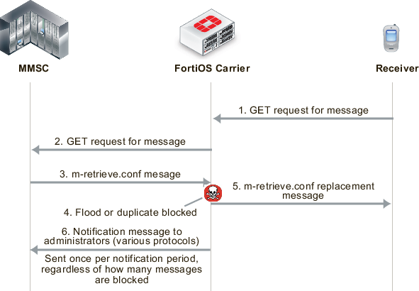
If FortiOS Carrier blocks the message (for example because a virus was found, see the figure below), FortiOS Carrier resets the connection to the MMSC and sends m-send.conf HTTP response back to the sender. The response message can be customized using replacement messages. FortiOS Carrier then terminates the connection. Sending back an m-send.conf message prevents the sender from trying to send the message again.
MM1 MMS scanning of message sent by sender (blocking m.send.req messages)
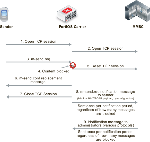
FortiOS Carrier also sends m-send.rec notifications messages to the MMSC that are then forwarded to the sender to notify them of blocked messages.
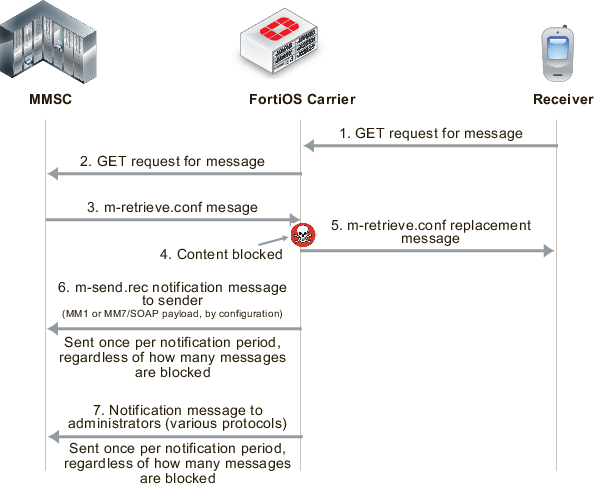
Filtering message retrieval
FortiOS Carrier intercepts the connection to the MMSC, and the m-retrieve.conf HTTP response from the MMSC is scanned according to the MMS content scanning settings. If the content is clean, the response is forwarded back to the client. If the content is blocked, FortiOS Carrier drops the connection to the MMSC. It then builds an m-retrieve.conf message from the associated replacement message and transmits this back to the client.
FortiOS Carrier also sends m-send.rec notifications messages to the MMSC that are then forwarded to the receiver to notify them of blocked messages.
MM1 MMS scanning of messages received by receiver (blocking m.retrieve.conf messages)
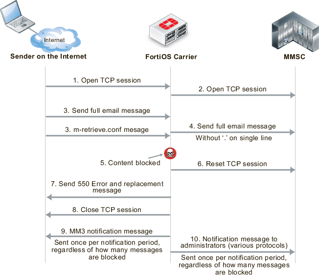
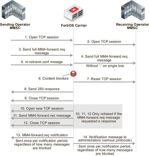
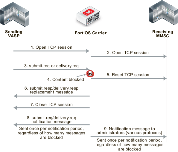
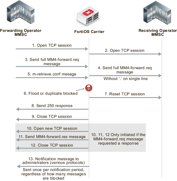
Filtering MM3 and MM4 messages works in an similar way to MM1 (see the figures below). FortiOS Carrier intercepts connections to the MMSC, and scans messages as configured. When messages are blocked, FortiOS Carrier closes sessions as required, sends confirmation messages to the sender, notifies administrators, and notifies senders and receivers of messages.
MM3 MMS scanning of messages sent from a sender on the Internet to an MMSC
MM4 MMS scanning of messages sent between operator MMSCs
MM7 MMS scanning of messages sent between a VASP and an MMSC
FortiOS Carrier and MMS duplicate messages and message floods
FortiOS Carrier detects duplicate messages and message floods for the MM1 and MM4 interfaces. How FortiOS Carrier detects and responds to duplicate messages and message floods is different from how FortiOS Carrier detects and responds to viruses and other MMS scanning protection measures.
For message floods and duplicate messages, the sender does not receive notifications about floods or duplicate messages, as if the sender is an attacker they can gain useful information about flood and duplicate thresholds. Plus, duplicate messages and message floods are usually a result of a large amount of messaging activity and filtering of these messages is designed to reduce the amount of unwanted messaging traffic. Adding to the traffic by sending notifications to senders and receivers could result in an increase in message traffic.
You can create up to three thresholds for detecting duplicate messages and message floods. For each threshold you can configure the FortiOS Carrier unit to respond by logging the activity, archiving or quarantining the messages, notifying administrators of the activity, and by blocking the messages. In many cases you may only want to configure blocking for higher activity thresholds, and to just monitor and send administrator notifications at lower activity thresholds.
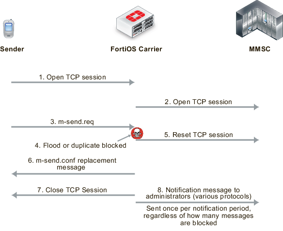
When a block threshold is reached for MM1 messages, FortiOS Carrier sends m-send.conf or m-retrieve.conf messages to the originator of the activity. These messages are sent to end the MM1 sessions, otherwise the originator would continue to re-send the blocked message. When a block threshold is reached for MM4, FortiOS Carrier sends a MM4-forward.res message to close the MM4 session. An MM4 message is sent only if initiated by the originating MM4-forward.req message.
MM1 message flood and duplicate message blocking of sent messages
MM1 message flood and duplicate message blocking of received messages
MM4 message flood and duplicate message blocking
MMS protection profiles
An MMS protection profile is a group of settings that you can apply to an MMS session matched by a security policy.
MMS protection profiles are easy to configure and can be used by more than one security policy. You can configure a single MMS protection profile for the different traffic types handled by a set of security policies that require identical protection levels and types. This eliminates the need to repeatedly configure those same MMS protection profile settings for each individual security policy.
For example, while traffic between trusted and untrusted networks might need strict protection, traffic between trusted internal addresses might need only moderate protection. You would configure two separate MMS protection profiles to provide the different levels of protection: one for traffic between trusted networks, and one for traffic between trusted and untrusted networks.
Once you have configured the MMS Protection Profile, you need to add it to a security policy to apply the profile to MMS traffic.
Bypassing MMS protection profile filtering based on carrier endpoints
You can use carrier endpoint filtering to exempt MMS sessions from MMS protection profile filtering. Carrier endpoint filtering matches carrier endpoints in MMS sessions with carrier endpoint patterns. If you add a carrier endpoint pattern to a filter list and set the action to exempt from all scanning, all messages from matching carrier endpoints bypass MMS protection profile filtering. See Bypassing message flood protection based on user’s carrier endpoints.
Applying MMS protection profiles to MMS traffic
To apply an MMS protection profile you must first create the MMS protection profile and then add the MMS protection profile to a security policy by enabling the Carrier security profile. The MMS protection profile then applies itself to the traffic accepted by that security policy.
MMS protection profiles can contain settings relevant to many different services. Each security policy uses the subset of the MMS protection profile settings that apply to the sessions accepted by the security policy. In this way, you might define just one MMS protection profile that can be used by many security policies, each policy using a different or overlapping subset of the MMS protection profile.
To add an MMS protection profile to a security policy
- Go to Security Profiles > Carrier > MMS Profile.
- Select Create New to add an MMS protection profile.
- Configure as needed, and save.
- Go to Policy & Objects > Policy > IPv4.
- Select Create New to add a security policy, or select an existing policy and Edit to add the MMS profile.
- Configure the security policy as required.
- Enable MMS Profile, and select the MMS profile to add to the security policy.
- Select OK.
GTP basic concepts
GPRS currently supports data rates from 9.6kbps to more than 100 kbps, and is best suited for burst forms of traffic. GPRS involves both radio and wired components. The mobile phone sends the message to a base station unit (radio based), and the base station unit sends the message to the carrier network and eventually the Internet (wired carrier network).
The network system then either sends the message back to a base station and to the destination mobile unit, or forwards the message to the proper carrier’s network where it gets routed to the mobile unit.
PDP Context
The packet data protocol (PDP) context is a connection between a mobile station and the end address that goes through the SGSN and GGSN. It includes identifying information about the mobile customer used by each server or device to properly forward the call data to the next hop in the carrier network, typically using a GTP tunnel between the SGSN and GGSN.
When a mobile customer has an active voice or data connection open, both the SGSN and GGSN have the PDP context information for that customer and session.
When a mobile phone attempts to communicate with an address on an external packet network, either an IP or X.25 address, the mobile station that phone is connected to opens a PDP context through the SGSN and GGSN to the end address. Before any traffic is sent, the PDP context must first be activated.
The information included in the PDP context includes the customer’s IP address, the IMSI number of the mobile handset, and the tunnel endpoint ID for both the SGSN and GGSN. The ID is a unique number, much like a session ID on a TCP/IP firewall. All this information ensures a uniquely identifiable connection is made.
Since one mobile device may have multiple connections open at one time, such as data connections to different Internet services and voice connections to different locations, there may be more than one PDP context with the same IP address making the extra identifying information required.
The endpoint that the mobile phone is connecting to only knows about the GGSN — the rest of the GPRS connection is masked by the GGSN.
Along the PDP context path, communication is accomplished in using three different protocols.
- The connection between the Mobile Station and SGSN uses the SM protocol.
- Between SGSN and GGSN GTP is used.
- Between GGSN and the endpoint either IP or X.25 is used.
FortiOS Carrier is concerned with the SGSN to GGSN part of the PDP context — the part that uses GTP.
For more about PDP context, see Tunnel Management Messages.
Creating a PDP context
While FortiOS Carrier is concerned mostly with the SGSN to GGSN part of the PDP Context, knowing the steps involved in creating a PDP context helps understand the role each device, protocol, and message type plays.
Both mobile stations and GGSNs can create PDP contexts.
A Mobile Station creates a PDP context
- The Mobile Station (MS) sends a
PDP activation requestmessage to the SGSN including the MS PDP address, and APN. - Optionally, security functions may be performed to authenticate the MS.
- The SGSN determines the GGSN address by using the APN identifier.
- The SGSN creates a downlink GTP tunnel to send IP packets between the GGSN and SGSN.
- The GGSN creates an entry in its PDP context table to deliver IP packets between the SGSN and the external packet switching network.
- The GGSN creates an uplink GTP tunnel to route IP-PDU from SGSN to GGSN.
- The GGSN then sends back to the SGSN the result of the PDP context creation and if necessary the MS PDP address.
- The SGSN sends an
Activate PDP context acceptmessage to the MS by returning negotiated the PDP context information and if necessary the MS PDP address. - Now traffic can pass from the MS to the external network endpoint.
A GGSN creates a PDP context
- The network receives an IP packet from an external network.
- The GGSN checks if the PDP Context has already been created.
- If not, the GGSN sends a
PDU notification requestto the SGSN in order to initiate a PDP context activation. - The GGSN retrieves the IP address of the appropriate SGSN address by interrogating the HLR from the IMSI identifier of the MS.
- The SGSN sends to the MS a request to activate the indicated PDP context.
- The PDP context activation procedure follows the one initiated by the MS. See “A Mobile Station creates a PDP context”.
- When the PDP context is activated, the IP packet can be sent from the GGSN to the MS.
Terminating a PDP context
A PDP context remains open until it is terminated. To terminate the PDP context an MS sends a Deactivate PDP context message to the SGSN, which then sends a Delete PDP Context message to the GGSN. When the SGSN receives a PDP context deletion acknowledgment from the GGSN, the SGSN confirms to the MS the PDP context deactivation. The PDP can be terminated by the SGSN or GGSN as well with a slight variation of the order of the messages passed.
When the PDP Context is terminated, the tunnel it was using is deleted as well. If this is not completed in a timely manner, it is possible for someone else to start using the tunnel before it is deleted. This hijacking will result in the original customer being overbilled for the extra usage. Anti-overbilling helps prevent this. See Configuring Anti-overbilling in FortiOS Carrier.
GPRS security
The GPRS network has some built-in security in the form of GPRS authentication. However this is minimal, and is not sufficient for carrier network security needs. A GTP firewall, such as FortiOS Carrier, is required to secure the Gi, Gn, and Gp interfaces.
GPRS authentication
GPRS authentication is handled by the SGSN to prevent unauthorized GPRS calls from reaching the GSM network beyond the SGSN (the base station system, and mobile station). Authentication is accomplished using some of the customer’s information with a random number and uses two algorithms to create ciphers that then allow authentication for that customer.
User identity confidentiality ensures that customer information stays between the mobile station and the SGSN — no identifying information goes past the SGSN. Past that point other numbers are used to identify the customer and their connection on the network.
Periodically the SGSN may request identity information from the mobile station to compare to what is on record, using the IMEI number.
Call confidentiality is achieved through the use of a cipher, similar to the GPRS authentication described earlier. The cipher is applied between the mobile station and the SGSN. Essentially a cipher mask is XORd with each outgoing frame, and the receiving side XORs with its own cipher to result in the original frame and data.
Parts of a GTPv1 network
A sample GTP network consists of the end handset sender, the sender’s mobile station, the carrier’s network including the SGSN and GGSN, the receiver's mobile station, and the receiver handset.
When a handset moves from one mobile station and SGSN to another, the handset’s connection to the Internet is preserved because the tunnel the handset has to the Internet using GTP tracks the user’s location and information. For example, the handset could move from one cell to another, or between countries.
The parts of a GPRS network can be separated into the following groups according to the roles of the devices:
- Radio access to the GPRS network is accomplished by mobile phones and mobile stations (MS).
- Transport the GPRS packets across the GPRS network is accomplished by SGSNs and GGSNs, both local and remote, by delivering packets to the external services.
- Billing and records are handled by CDF, CFR, HLR, and VLR devices.
GPRS networks also rely on access points and PDP contexts as central parts of the communication structure. These are not actual devices, but they are still critical .
These devices, their roles, neighboring devices, the interfaces and protocols they use are outlined in the following table.
Carrier network showing the interfaces used (GTPv1)
Devices on a GTPv1 network
| Device role | Neighboring Devices | Interfaces used | Protocols used |
|---|---|---|---|
| Mobile Users | Mobile Stations (MS) | Radio Access Technology (RAT) | |
| Mobile Stations (MS) | Mobile Users, SGSN | Gb | IP, Frame Relay |
| SGSN (local) | MS, SGSN (local or remote), GGSN (local and remote), CDR, CFR, HLR, VLR | Ga, Gb, Gn, Gp, Gz | IP, Frame Relay, GTP, GTP’ |
| SGSN (remote) | SGSN (local) | Gn | GTP |
| GGSN (local) | SGSN (local or remote), GGSN (local and remote), CDR, CFR, HLR, VLR | Ga, Gi, Gn, Gp, Gz | IP, GTP, GTP’ |
| GGSN (remote) | SGSN (local), WAP gateway, Internet, other external services | Gi, Gp | IP, GTPv1 |
| CDR, CFR | SGSN (local), GGSN (local) | Ga, Gz | GTP’ |
| HLR, VLR | SGSN (local), GGSN (local) | Ga, Gz | GTP’ |
Radio access
For a mobile phone to access the GPRS core network, it must first connect to a mobile station. This is a cellular tower that is connected to the carrier network.
How the mobile phone connects to the mobile station (MS) is determined by what Radio Access Technologies (RATs) are supported by the MS.
Transport
Transport protocols move data along the carrier network between radio access and the Internet or other carrier networks.
FortiOS Carrier should be present where information enters the Carrier network, to ensure the information entering is correct and not malicious. This means a Carrier-enabled FortiGate unit intercepts the data coming from the SGSN or foreign networks destined for the SSGN or GGSN onto the network, and after the GGSN as the data is leaving the network.
GTP
GPRS Tunnelling Protocol (GTP) is a group of IP-based communications protocols used to carry General Packet Radio Service (GPRS) within Global System for Mobile Communications (GSM) and Universal Mobile Telecommunications System (UMTS) networks. It allows carriers to transport actual cellular packets over their network via tunneling. This tunneling allows users to move between SGSNs and still maintain connection to the the Internet through the GGSN.
GTP has three versions version 0, 1, and 2. GTP1 and GTP2 are supported by FortiOS Carrier. The only GTP commands that are common to all forms of GTP are the echo request/response commands that allow GSNs to verify up to once every 60 seconds that neighboring GSNs are alive.
GTPv0
There have been three versions of GTP to date. The original version of GTP (version 0) has the following differences from version GTPv1.
- the tunnel identification is not random
- there are options for transporting X.25
- the fixed port number 3386 is used for all functions, not just charging
- optionally TCP is allowed as a transport instead of UDP
- not all message types are supported in version 0
GTPv1
On a GPRS network, Packet Data Protocol (PDP) context is a data structure used by both the Serving GPRS Support Node (SGSN) and the Gateway GPRS Support Node (GGSN). The PDP context contains the subscribers information including their access point, IP address, IMSI number, and their tunnel endpoint ID for each of the SGSN and GGSN.
The Serving GPRS Support Node (SGSN) is responsible for the delivery of data packets from and to the mobile stations within its geographical service area. Its tasks include packet routing and transfer, mobility management (attach/detach and location management), logical link management, and authentication and charging functions. The location register of the SGSN stores location information (e.g., current cell, current VLR) and user profiles (e.g., IMSI, address(es) used in the packet data network) of all GPRS users registered with this SGSN.
GTPv1-C
GTPv1-C refers to the control layer of the GPRS Transmission network. This part of the protocol deals with network related traffic.
FortiOS Carrier handles GTPv1-C in GTPv1 by using the Tunnel Endpoint IDentifier (TEID), IP address and a Network layer Service Access Point Identifier (NSAPI), sometimes called the application identifier, as an integer value that is part of the PDP context header information used to identify a unique PDP context in a mobile station, and SGSN.
For more information on GTPv1-C, see GTP-C messages.
GTPv1-U
GTPv1-U is defined in 3GPP TS 29.281 and refers to the user layer of the GPRS Tunneling network. This part of the protocol deals with user related traffic, user tunnels, and user administration issues.
A GTPv1-U tunnel is identified by a TEID, an IP address, and a UDP port number. This information uniquely identifies the limb of a GTPv1 PDP context. The IP address and the UDP port number define a UDP/IP path, a connectionless path between two endpoints (i.e. SGSN or GGSN). The TEID identifies the tunnel endpoint in the receiving GTPv1-U protocol entity; it allows for the multiplexing and demultiplexing of GTP tunnels on a UDP/IP path between a given GSN-GSN pair. For more information on GTPv1-U, see GTP-U messages.
The GTP core network consists of one or more SGSNs and GGSNs.
GGSN
The Gateway GPRS Support Node (GGSN) connects the GPRS network on one side via the SGSN to outside networks such as the Internet. These outside networks are called packet data networks (PDNs). The GGSN acts as an edge router between the two different networks — the GGSN forwards incoming packets from the external PDN to the addressed SGSN and the GGSN also forwards outgoing packets to the external PDN. the GGSN also converts the packets from the GPRS packets with SGSN to the external packets, such as IP or X.25.
SGSN
The Serving GPRS Support Node (SGSN) connects the GPRS network to GTPv1 compatible mobile stations, and mobile units (such as UTRAN and ETRAN) on one side and to the gateway node (GGSN), which leads to external networks, on the other side. Each SGSN has a geographical area, and mobile phones in that area connect to the GPRS network through this SGSN. The SGSN also maintains a location register that contains customer’s location and user profiles until they connect through a different SGSN at which time the customer information is moved to the new SGSN. This information is used for packet routing and transfer, mobility management also known as location management, logical link management, and authentication and billing functions.
GTPv2
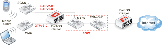
GTPv2, defined in 3GPP TS 29.274, is dramatically differnet from GTPv1, defined in 3GPP TS 29.060. Where in GTPv1 the tunnel is between the SGSN and the GGSN, in GTPv2 The SGSN is between the MME and the LTE Serving Gateway (S-GW), beyond which is the PDN gateway (P-GW). Even tunnel management messages have changed significantly.
Network diagram for GTPv2
Device roles on a GTPv2 network
| Device role | Neighboring Devices | Interfaces used | Protocols used |
|---|---|---|---|
| Mobile Users | Mobile Stations (MS) | Radio Access Technology (RAT) | -- |
| GTPv1 Mobile Stations (MS) | Mobile Users, SGSN | Gb | IP, Frame Relay |
| GTPv2 Mobile Stations (MS) | Mobile Users, MME | ??? | IP, Frame Relay |
| SGSN (local) | GTPv1 MS, SGSN, S-GW | ??? | IP, Frame Relay, GTPv1, GTP’ |
| S-GW | SGSN, MME, P-GW | ??? | IP, GTPv2, GTP’ |
| P-GW | S-GW, Internet, other external services | ??? | IP, GTPv2 |
GTPv2-C
GTPv2-C is the control layer messaging for GTPv2. It is used by LTE mobile stations, SGSN units for backwards compatibility, and SGWs that are the gateway to other networks. The messaging is very different from GTPv1. GTPv2-C is required to communicate with the Mobility Management Entity (MME) to create, change and delete EPS bearers when handover events happen, and to create Forwarding tunnels. The protocol is also used to communicate with the Serving Gateway (SGW) which has the S-GW and PDN-GW interfaces, and the Serving GPRS Support Node (SGSN).
MME
MME essentially fills the role of the SGSN in a GTPv1 network — it is how the mobile stations gain access to the Carrier network. GTPv2 supports different mobile stations than GTPv1, so MME handles the GTPv2 MSes and SGSN handles the GTPv1 MSes
Billing and records
A major part of the GPRS network is devoted to billing. Customer billing requires enough information to identify the customer, and then billing specific information such as connection locations and times, as well as amount of data transferred. A modified form of GTP called GTP’ is used for billing. The home location records and visitor location records store information about customers that is critical to billing.
GTP’ (GTP prime)
GTP is used to handle tunnels of user traffic between SGSNs and GGSNs. However for billing purposes, other devices that are not supported by GTP are required. GTP’ (GTP prime) is a modified form of GTP and is used to communicate with these devices such as the Charging Data Function (CDF) that communicates billing information to the Charging Gateway Function (CGF). In most cases, GTP‘ transports user records from many individual network elements, such as the GGSNs, to a centralised computer which then delivers the charging data more conveniently to the network operator's billing center, often through the CGF. The core network sends charging information to the CGF, typically including PDP context activation times and the quantity of data which the end user has transferred.
GTP’ is used by the Ga and Gz interfaces to transfer billing information. GTP’ uses registered UDP/TCP port 3386. GTP’ defines a different header, additional messages, field values, as well as a synchronisation protocol to avoid losing or duplicating CDRs on CGF or SGSN/GGSN failure. Transferred CDRs are encoded in ASN.1.
HLR
The Home Location Register (HLR) is a central database that contains details of each mobile phone subscriber that is authorized to use the GSM core network. There can be several logical, and physical, HLRs per public land mobile network (PLMN), though one international mobile subscriber identity (IMSI)/MSISDN pair can be associated with only one logical HLR (which can span several physical nodes) at a time. The HLRs store details of every SIM card issued by the mobile phone operator. Each SIM has a unique identifier called an IMSI which is the primary key to each HLR record.
VLR
The Visitor Location Register (VLR) is a database which stores information about all the mobile devices that are currently under the jurisdiction of the Mobile Switching Center which it serves. Of all the information the VLR stores about each Mobile Station, the most important is the current Location Area Identity (LAI). This information is vital in the call setup process.
Whenever an MSC detects a new MS in its network, in addition to creating a new record in the VLR, it also updates the HLR of the mobile subscriber, informing it of the new location of that MS.
For more information on GTP‘, see GTP-U and Charging Management Messages.
GPRS network common interfaces
There are interfaces for each connection on the GPRS network. An interface is an established standard form of communication between two devices. Consider a TCP/IP network. In addition to the transport protocol (TCP) there are other protocols on that network that describe how devices can expect communications to be organized, just like GPRS interfaces.
Interfaces between devices on the network
There are a series of interfaces that define how different devices on the carrier network communicate with each other. There interfaces are called Ga to Gz, and each one defines how a specific pair of devices will communicate. For example Gb is the interface between the base station and the SGSN, and Gn is one possible interface between the SGSN and GGSN.
The SGSN and GGSN keep track of the CDR information and forward it to the Charging Data Function (CDF) using the Gr interface between the SGSN and home location register (HLR), Gs interface between the SGSN and MSC (VLR), Gx interface between the GGSN and the Charging Rules Function (CRF), Gy between the GGSN and online charging system (OCS), and finally Gz which is the off-line (CDR-based) charging interface between the GSN and the CG that uses GTP'.
Each of these interfaces on the GPRS network is has a name in the format of Gx where x is a letter of the alphabet that determines what part of the network the interface is used in. It is common for network diagrams of GPRS networks to include the interface name on connections between devices.
|
|
The Carrier-enabled FortiGate unit only provides protection on the Gn, Gp, and Gi interfaces. |
GPRS network interfaces, their roles, and billing
| Name | Device connections that use this interface | Traffic Protocol used | Its role or how it affects billing |
|---|---|---|---|
| Ga | CDR and GSN (SGSNs and GGSNs) | GTP‘ - GTP modified to include CDR role | CDR have the accounting records, that are compiled in the GSN and then sent to the Charging Gateway (CG) |
| Gb | MS and SGSN | Frame Relay or IP | When an IP address moves to a new MS, the old MS may continue to use and bill that IP address. |
| Gi | GGSN and public data networks (PDNs) | IP based | This is the connection to the Internet. If the GTP tunnel is deleted without notifying the Gi interface, the connection may remain open incurring additional charges. FortiOS Carrier adds this interface to a firewall. See Anti-overbilling with FortiOS Carrier. |
| Gn | SGSN and external SGSNs and internal GGSNs | GTP | When the GTP tunnel is deleted, need to inform other interfaces immediately to prevent misuse of connections remaining open. FortiOS Carrier adds this interface to a firewall. |
| Gp | Internal SGSN and external GGSNs | GTP | |
| Gz | GSN (SGSN and GGSN) and the charging gateway (CG) | GTP‘ | Used for the offline charging interface. Ga is used for online charging. |
Corporate customers may have a direct connection to the Gi interface for higher security. The Gi interface is normally an IP network, though a tunnelling protocol such as GRE or IPsec may be used instead.
Packet flow through the GPRS network
To better understand the GPRS network, we will follow the path data takes for a normal connection. For this example a call placed from a mobile phone involves accessing services on the Internet.
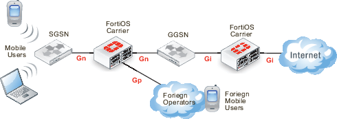
Sample GPRS network topology
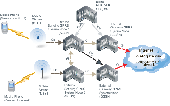
- A mobile phone places a call using a mobile station (MS). This connection between the mobile phone and the MS is a radio connection using one of the radio access technologies. See Radio Access Technology (RAT) type.
- The MS connects to a GPRS System Node (GSN) specifically a Sending GSN. This connection uses the Gb interface and typically uses IP address or Frame Relay.
- The SGSN checks the mobile phone information located in the home location register (HLR) or visitor location register (VLR) to ensure there is subscriber information for that phone. If this mobile phone is from another network, the SGSN uses the VLR and updates its home carrier’s information with its current location and information. This connection involves the Ga or Gz interfaces, and uses the GTP’ protocol for communication.
- The SGSN checks to make sure the phone did not transfer this connection from a different MS. If it did, the connection has already been established (along with the billing) and is handed off to this SGSN. If the call is being handed over from another SGSN, it will use the Gn interface between the two SGSNs.
- The SGSN sends GTP messages to the local external Gateway GSN (GGSN) to create a GTP tunnel for this PDP context to access the Internet. It is possible that a remote GGSN has access to a service, such as a WAP gateway, that the local GGSN is missing. In this situation, the local SGSN uses the Gp interface to connect to the remote GGSN. Both the Gn and Gp interfaces use GTP.
- The both the local and remote GGSNs connect to external services outside the GPRS network. These services can include a WAP gateway, a corporate IP network directly connected to the GPRS network, or the Internet. The connection from the GGSN to the external services uses the Gi interface.
SCTP
As of FortiOS version 5.0, the FortiGate natively handles SCTP (Stream Control Transport Protocol) traffic, as an alternative to TCP and UDP for use in Carrier networks. The FortiGate handles SCTP as if it would any other traffic.
Overview
SCTP is a connection-oriented transport protocol that overcomes some of the limitations of both TCP and UDP that prevent reliable transfer of data over IP-based networks (such as those used by telephony systems and carrier networks). The ‘Stream’ in SCTP refers to the sequence of user messages or packets that are considered at the same time to be individual objects and also treated as a whole by networked systems. SCTP is less vulnerable to congestion and flooding due to more advanced error handling and flood protection built into the protocol.
SCTP features as compared to TCP and UDP
| Feature | SCTP | TCP | UDP |
|---|---|---|---|
| State required at each endpoint | yes | yes | no |
| Reliable data transfer | yes | yes | no |
| Congestion control and avoidance | yes | yes | no |
| Message boundary conservation | yes | no | yes |
| Path MTU discovery and message fragmentation | yes | yes | no |
| Message bundling | yes | yes | no |
| Multi-homed hosts support | yes | no | no |
| Multi-stream support | yes | no | no |
| Unordered data delivery | yes | no | yes |
| Security cookie against SYN flood attack | yes | no | no |
| Built-in heartbeat (reachability check) | yes | no | N/A |
All of these features are built into the design of the Protocol, and the structure of SCTP packets and networks. The FortiGate unit interprets the traffic and provides the necessary support for maintenance and verification features, but the features are not FortiGate specific. These features are documented in greater detail below.
State required at each endpoint
Constant back and forth acknowledgement and content verification messages are sent between all SCTP peer endpoints, and all endpoints’ state machine actions must be synchronized for traffic to flow.
Reliable data transfer
SCTP places data and control information (eg. source, destination, verification) into separate messages, both sharing the same header in the same SCTP packet. This allows for constant verification of the contained data at both ends and along the path, preventing data loss or fragmentation. As well, data is not sent in an interruptible stream as in TCP.
Congestion control and avoidance
Built-in, constantly updating path detection and monitoring automatically redirect packets along alternate paths in case of traffic congestion or inaccessible destinations. For deliberate/malicious congestion control, see the below section on Security cookie against SYN flood attack.
Message boundary conservation
SCTP is designed in such a way that no matter how messages are divided, redirected, or fragmented, the message boundaries will be maintained within the packets, and all messages cannot be appended without tripping verification mechanisms.
Path MTU discovery and message fragmentation
SCTP is capable of Path Maximum Transmission Unit discovery, as outlined in RFC4821. Two specific alterations have been made to how SCTP handles MTU. First, that endpoints will have separate MTU estimates for each possible multi-homed endpoint. Second, that bundled message fragments (as explained below) will be directed based on MTU calculations, so that retransmissions (if necessary) will be sent without delay to alternate addresses.
Message bundling
SCTP is a message-oriented protocol, which means that despite being a streaming data protocol, it transports a sequence of specific messages, rather than transporting a stream of bytes (like TCP). Since some data transmissions are small enough to not require a complete message’s worth of content, so multiple pieces of content will be transmitted simultaneously within the messages.
Multi-homed hosts support
SCTP supports multi-homing, which is a network structure in which one or multiple sources/destinations has more than one IP address. SCTP can adapt to multi-homing scenarios and redirect traffic to alternate IP addresses in case of failure.
Multi-stream support
Due to the message bundling feature allowing for multiple pieces of content to be sent in messages at once, SCTP can ‘multi-stream’ content, by deliberately dividing it among messages at a fixed rate, so that multiple types of content (eg. both images and text) can be loaded at once, at the same pace.
Unordered data delivery
With control messages in every packet to provide verification of any packet’s data and its place in the stream, the data being transmitted can actually arrive in any order, and verify that all has arrived or that some is missing.
Security cookie against SYN flood attack
Since every packet contains verification of its place in the stream, it makes it easy for the protocol to detect when redundant, corrupted or malicious packets flood the path, and they are automatically dropped when necessary.
Built-in heartbeat (reachability check)
Endpoints automatically send specific control chunks among the other SCTP packet information to peer endpoints, to determine the reachability of the destination. Hearthbeat acknowledgement packets are returned if the destination is available.
SCTP Firewall
FortiGate stateful firewalls will protect and inspect SCTP traffic, according to RFC4960. SCTP over IPsec VPN is also supported. The FortiGate device is inserted as a router between SCTP endpoints. It checks SCTP Syntax for the following information:
- Source and destination port
- Verification Tag
- Chunk type, chunk flags, chunk length
- Sequence of chunk types
- Associations
The firewall also oversees and maintains several SCTP security mechanisms:
- SCTP four-way handshake
- SCTP heartbeat
- NAT over SCTP
The firewall has IPS DoS protection against known threats to SCTP traffic, including INIT/ACK flood attacks, and SCTP fuzzing.
SCTP example scenario
An ideal SCTP configuration for a Carrier serving multiple operators/service providers involves a unified Firewall, securing all incoming and outgoing traffic over the Carrier network, whether it be standard web traffic, GTP or other carrier traffic, or corporate traffic for the Carrier company.
One best practice method to provide a unified firewall with built-in redundancy is to make use of multiple FortiGate units, connected in a High Availability cluster. Also, there are additional methods that can be applied to ease the complexity of managing multiple services, functions, and traffic types across multiple devices.
Sample SCTP Network Topology
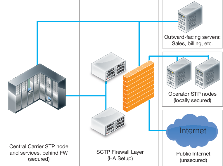
In this example, the firewall layer is configured with two FortiGate devices to act as an HA cluster, providing automatic load balancing and failover detection for the main firewall.
The two devices together make up the firewall, through which all traffic passes. Virtual Domains are created within the FortiGate units, distributing services and traffic into individual VDOMs, allowing them to be monitored and secured individually, to help mitigate possible threats to Carrier networks that target specific services. Individual departments or administrators can manage specific VDOMs, or the FortiGates can be collectively managed centrally by network administrators.
The VDOMs are distributed as shown below:
VDOM distribution between SCTP Firewall Layer FortiGate units
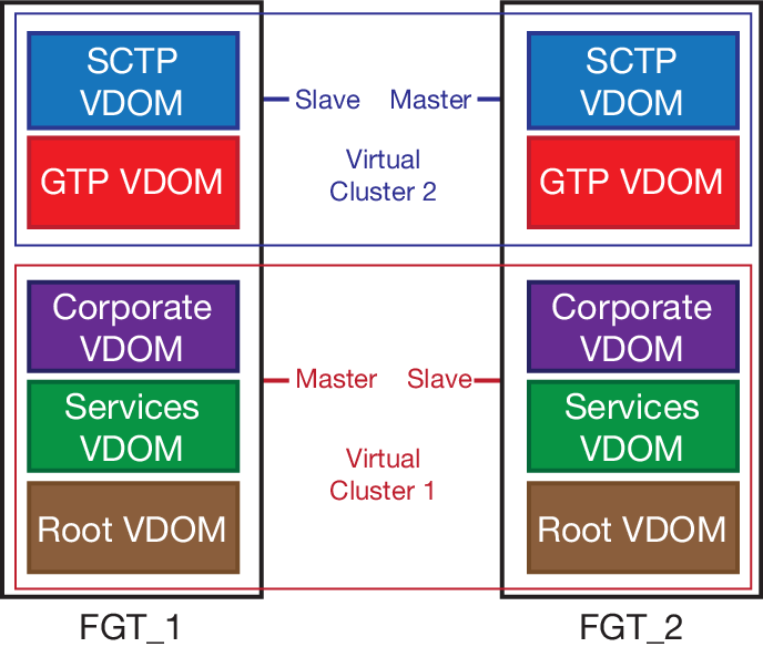
One FortiGate handles basic FortiGate services and non-Carrier traffic. Configuring virtual clustering across the two FortiGates allows one to mirror its VDOMs across to the other unit.
The second FortiGate can then primarily provide Carrier-specific services and handle SCTP, Gi and GTP traffic, using the first FortiGate as the slave unit in a second virtual cluster.
Copyright © 2018 Fortinet, Inc. All Rights Reserved. | Terms of Service | Privacy Policy
