
Virtual Domains in Transparent mode
In Transparent mode, the FortiGate unit behaves like a layer-2 bridge but can still provide services such as antivirus scanning, web filtering, spam filtering and intrusion protection to traffic. There are some limitations in Transparent mode in that you cannot use SSL VPN, PPTP/L2TP VPN, DHCP server, or easily perform NAT on traffic. The limits in Transparent mode apply to IEEE 802.1Q VLAN trunks passing through the unit.
VDOMs can each be configured to operate either in Transparent or NAT/Route operation mode, with each VDOM behaving like a separate FortiGate unit operating in the respective mode. VLANs configured on a VDOM in Transparent mode are the same as VLANs configured on the FortiGate unit when VDOMs are disabled.
This chapter includes the following sections:
- Transparent operation mode
- Configuring VDOMs in Transparent mode
- Example of VDOMs in Transparent mode
Transparent operation mode
In transparent mode, the FortiGate unit becomes a layer-2 IP forwarding bridge. This means that Ethernet frames are forwarded based on destination MAC address, and no other routing is performed. All incoming traffic that is accepted by the firewall, is broadcast out on all interfaces.
In transparent mode the FortiGate unit is a forwarding bridge, not a switch. A switch can develop a port table and associated MAC addresses, so that it can bridge two ports to deliver the traffic instead of broadcasting to all ports. In transparent mode, the FortiGate unit does not following this switch behavior, but instead is the forwarding bridge that broadcasts all packets out over all interfaces, subject to security policies.
Features such as broadcast domains, forwarding domains, and STP apply to both FortiGate units and VDOMs in Transparent mode.
Broadcast domains
A broadcast domain is a network segment in which any network equipment can transmit data directly to another device without going through a routing device. All the devices share the same subnet. The subnets are separated by layer-3 devices, such as routers, that can forward traffic from one broadcast domain to the next.
Broadcast domains are important to transparent mode FortiGate units because the broadcast domain is the limit of where the FortiGate unit can forward packets when it is in transparent mode.
Forwarding domains
Address Resolution Protocol (ARP) packets are vital to communication on a network, and ARP support is enabled on FortiGate unit interfaces by default. Normally you want ARP packets to pass through the FortiGate unit. However, in Transparent mode ARP packets arriving on one interface are sent to all other interfaces including VLANs giving the appearance of duplicates of the same MAC address on different interfaces. Some layer-2 switches become unstable when they detect these duplicate MAC addresses. Unstable switches may become unreliable or reset and cause network traffic to slow down considerably.
When you are using VLANs in Transparent mode, the solution to the duplicate MAC address issue is to use the forward-domain CLI command. This command tags VLAN traffic as belonging to a particular collision group, and only VLANs tagged as part of that collision group receive that traffic—it is like an additional set of VLANs. By default, all interfaces and VLANs are part of forward-domain collision group 0.
To assign VLAN 200 to collision group 2, VLAN 300 to collision group 3, and all other interfaces to stay in the default collision group 0 enter the following CLI commands:
config system interface
edit vlan200
set vlanid 200
set forward_domain 2
next
edit vlan300
set vlanid 300
set forward_domain 3
next
end
When using forwarding domains, you may experience connection issues with layer-2 traffic, such as ping, if your network configuration has
- packets going through the FortiGate unit in Transparent mode multiple times,
- more than one forwarding domain (such as incoming on one forwarding domain and outgoing on another)
- IPS and AV enabled.
Spanning Tree Protocol
VDOMs and FortiGate units do not participate in the Spanning Tree Protocol (STP). STP is an IEEE 802.1 protocol that ensures there are no layer-2 loops on the network. Loops are created when there is more than one route for traffic to take and that traffic is broadcast back to the original switch. This loop floods the network with traffic, quickly reducing available bandwidth to zero.
If you use your VDOM or FortiGate unit in a network topology that relies on STP for network loop protection, you need to make changes to your FortiGate configuration. Otherwise, STP recognizes your FortiGate unit as a blocked link and forwards the data to another path. By default, your FortiGate unit blocks STP as well as other non-IP protocol traffic. Using the CLI, you can enable forwarding of STP and other layer-2 protocols through the interface. In this example, layer-2 forwarding is enabled on the port2 interface:
config global
config system interface
edit port2
set l2forward enable
set stpforward enable
next
end
There are different CLI commands to allow other common layer-2 protocols such as IPX, PPTP or L2TP on the network. For more information, see the FortiOS CLI Reference.
Differences between NAT/Route and Transparent mode
The differences between NAT/Route mode and Transparent mode include:
Differences between NAT/Route and Transparent modes
| Features | NAT/Route mode | Transparent mode |
|---|---|---|
| Specific Management IP address required | No | Yes |
| Perform Network Address Translation (NAT) | Yes | Yes |
| Stateful packet inspection | Yes | Yes |
| Layer-2 forwarding | Yes | Yes |
| Layer-3 routing | Yes | No |
| Unicast Routing / Policy Based routing | Yes | No |
| DHCP server | Yes | No |
| IPsec VPN | Yes | Yes |
| PPTP/L2TP VPN | Yes | No |
| SSL VPN | Yes | No |
| Security features | Yes | Yes |
| VLAN support | Yes | Yes - limited to VLAN trunks. |
| Ping servers (dead gateway detection) | Yes | No |
To provide administrative access to a FortiGate unit or VDOM in Transparent mode, you must define a management IP address and a gateway. This step is not required in NAT/Route mode where you can access the FortiGate unit through the assigned IP address of any interface where administrative access is permitted.
If you incorrectly set the Transparent mode management IP address for your FortiGate unit, you will be unable to access your unit through the web-based manager. In this situation, you will need to connect to the FortiGate unit using the console cable and change the settings so you can access the unit. Alternately, if your unit has an LCD panel, you can change the operation mode and interface information through the LCD panel.
Operation mode differences in VDOMs
A VDOM, such as root, can have a maximum of 255 interfaces in Network Address Translation (NAT) mode or Transparent mode. This includes VLANs, other virtual interfaces, and physical interfaces. To have more than a total of 255 interfaces configured, you need multiple VDOMs with multiple interfaces on each.
In Transparent mode without VDOMs enabled, all interfaces on the FortiGate unit act as a bridge — all traffic coming in on one interface is sent back out on all the other interfaces. This effectively turns the FortiGate unit into a two interface unit no matter how many physical interfaces it has. When VDOMs are enabled, this allows you to determine how many interfaces to assign to a VDOM running in Transparent mode. If there are reasons for assigning more than two interfaces based on your network topology, you are able to. However, the benefit of VDOMs in this case is that you have the functionality of Transparent mode, but you can use interfaces for NAT/Route traffic as well.
You can add more VDOMs to separate groups of VLAN subinterfaces. When using a FortiGate unit to serve multiple organizations, this configuration simplifies administration because you see only the security policies and settings for the VDOM you are configuring. For information on adding and configuring virtual domains, see Benefits of Virtual Domains.
One essential application of VDOMs is to prevent problems caused when a FortiGate unit is connected to a layer-2 switch that has a global MAC table. FortiGate units normally forward ARP requests to all interfaces, including VLAN subinterfaces. It is then possible for the switch to receive duplicate ARP packets on different VLANs. Some layer-2 switches reset when this happens. As ARP requests are only forwarded to interfaces in the same VDOM, you can solve this problem by creating a VDOM for each VLAN. For a configuration example, see Example of VDOMs in Transparent mode.
Configuring VDOMs in Transparent mode
In Transparent mode, your FortiGate unit becomes a layer-2 bridge — any traffic coming in on one port is broadcast out on all the other ports. If your FortiGate unit has many interfaces, this is not the best use of those interfaces. VDOMs can limit Transparent mode to only a few interfaces while allowing the rest of the FortiGate unit to remain in NAT/Route mode.
The essential steps to configure your FortiGate unit to work with VLANs in Transparent mode are:
You can also configure the security profiles that manage antivirus scanning, web filtering and spam filtering.
In Transparent mode, you can access the FortiGate web-based manager by connecting to an interface configured for administrative access and using HTTPS to access the management IP address. On the FortiGateunit used for examples in this guide, administrative access is enabled by default on the internal interface and the default management IP address is 10.11.0.1.
Switching to Transparent mode
A VDOM is in NAT/Route mode by default when it is created. You must switch it to Transparent mode, and add a management IP address so you can access the VDOM from your management computer.
|
|
Before applying the change to Transparent mode, ensure the VDOM has administrative access on the selected interface, and that the selected management IP address is reachable on your network. |
To switch the tpVDOM VDOM to Transparent mode - web-based manager:
- Go to Global > VDOM > VDOM.
- Edit the tpVDOM.
- Select
Transparentfor Operation mode. - Enter the management IP/Netmask.
The IP address must be accessible to the subnet where the management computer is located. For example 10.11.0.99/255.255.255.0 will be able to access the 10.11.0.0 subnet. - Select Apply.
When you select Apply, the FortiGate unit will log you out. When you log back in, the VDOM will be in Transparent mode.
To switch the tpVDOM VDOM to Transparent mode - CLI:
config vdom
edit tpVDOM
config system settings
set opmode transparent
set mangeip 10.11.0.99 255.255.255.0
end
end
Adding VLAN subinterfaces
There are a few differences when adding VLANs in Transparent mode compared to NAT/Route mode.
In Transparent mode, VLAN traffic is trunked across the VDOM. That means VLAN traffic cannot be routed, changed, or inspected. For this reason when you assign a VLAN to a Transparent mode VDOM, you will see the Addressing Mode section of the interface configuration disappear in from the web-based manager. It is because with no routing, inspection, or any activities able to be performed on VLAN traffic the VDOM simply re-broadcasts the VLAN traffic. This requires no addressing.
Also any routing related features such as dynamic routing or Virtual Router Redundancy Protocol (VRRP) are not available in Transparent mode for any interfaces.
Creating security policies
Security policies permit communication between the FortiGate unit’s network interfaces based on source and destination IP addresses. Typically you will also limit communication to desired times and services for additional security.
In Transparent mode, the FortiGate unit performs antivirus and antispam scanning on each packet as it passes through the unit. You need security policies to permit packets to pass from the VLAN interface where they enter the unit to the VLAN interface where they exit the unit. If there are no security policies configured, no packets will be allowed to pass from one interface to another. For more information, see the FortiGate Administration Guide.
Example of VDOMs in Transparent mode
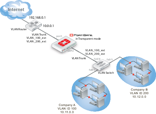
In this example, the FortiGate unit provides network protection to two organizations — Company A and Company B. Each company has different policies for incoming and outgoing traffic, requiring three different security policies and protection profiles.
VDOMs are not required for this configuration, but by using VDOMs the profiles and policies can be more easily managed on a per-VDOM basis either by one central administrator or separate administrators for each company. Also future expansion is simply a matter of adding additional VDOMs, whilst not disrupt the existing VDOMs.
For this example, firewalls are only included to deal with web traffic. This is to provide an example without making configuration unnecessarily complicated.
This example includes the following sections:
- Network topology and assumptions
- General configuration steps
- Configuring common items
- Creating virtual domains
- Configuring the Company_A VDOM
- Configuring the Company_B VDOM
- Virtual Domains in Transparent mode
- Testing the configuration
Network topology and assumptions
Each organization’s internal network consists of a different range of IP addresses:
- 10.11.0.0.0/255.255.0.0 for Company A.
- 10.12.0.0/255.255.0.0 for Company B.
For the procedures in this section, it is assumed that you have enabled VDOM configuration on your FortiGate unit. For more information, see Enabling and accessing Virtual Domains.
The VDOM names are similar to the company names for easy recognition. The root VDOM cannot be renamed and is not used in this example.
Interfaces used in this example are port1 and port2. Some FortiGate models may not have interfaces with these names. port1 is an external interface. port2 is an internal interface.
Figure 10: VLAN and VDOM Transparent example network topology
General configuration steps
The following steps summarize the configuration for this example. For best results, follow the procedures in the order given. Also, note that if you perform any additional actions between procedures, your configuration may have different results.
- Configuring common items
- Creating virtual domains
- Configuring the Company_A VDOM
- Configuring the Company_B VDOM
- Virtual Domains in Transparent mode
- Testing the configuration
Configuring common items
Both VDOMs require you configure security profiles. These will be configured the same way, but need to be configured in both VDOMs.
The relaxed profile allows users to surf websites they are not allowed to visit during normal business hours. Also a quota is in place to restrict users to one hour of access to these websites to ensure employees do not take long and unproductive lunches.
To create a strict web filtering profile - web-based manager:
- Go to the proper VDOM, and select Security Profiles > Web Filter > Profile.
- Select Create New.
- Enter
strictfor the Name. - Expand FortiGuard Web Filtering, and select block for all Categories except Business Oriented, and Other.
- Block all Classifications except Cached Content, and Image Search.
- Ensure FortiGuard Quota for all Categories and Classifications is Disabled.
- Select OK.
To create a strict web filtering profile - CLI:
config vdom
edit <vdom_name>
config webfilter profile
edit strict
config ftgd-wf
set allow g07 g08 g21 g22 c01 c03
set deny g01 g02 g03 g04 g05 g06 c02 c04 c05 c06 c07
end
set web-ftgd-err-log enable
end
To create a relaxed web filtering profile - web-based manager:
- Go to the proper VDOM, and select Security Profiles > Web Filter > Profile.
- Select Create New.
- Enter
relaxedfor the Name. - Expand FortiGuard Web Filtering, and select block for Potentially Security Violating Category, and Spam URL Classification.
- Enable FortiGuard Quotas to allow 1 hour for all allowed Categories and Classifications.
Creating virtual domains
The FortiGate unit supports 10 virtual domains. Root is the default VDOM. It cannot be deleted or renamed. The root VDOM is not used in this example. New VDOMs are created for Company A and Company B
To create the virtual domains - web-based manager:
- With VDOMs enabled, select System > VDOM > VDOM.
- Select Create New.
- Enter
Company_Afor Name, and select OK. - Select Create New.
- Enter
Company_Bfor Name, and select OK.
To create the virtual domains - CLI:
config system vdom
edit Company_A
next
edit Company_B
end
Configuring the Company_A VDOM
This section describes how to add VLAN subinterfaces and configure security policies for the Company_A VDOM.
This section includes the following topics:
- Adding VLAN subinterfaces
- Creating the Lunch schedule
- Configuring Company_A firewall addresses
- Creating Company_A security policies
Adding VLAN subinterfaces
You need to create a VLAN subinterface on the port2 interface and another one on the port1 interface, both with the same VLAN ID.
To add VLAN subinterfaces - web-based manager:
- Go to System > Network > Interfaces.
- Select Create New.
- Enter the following information and select OK:
| Name | VLAN_100_int |
| Interface | port2 |
| VLAN ID | 100 |
| Virtual Domain | Company_A |
- Select Create New.
- Enter the following information and select OK:
| Name | VLAN_100_ext |
| Interface | port1 |
| VLAN ID | 100 |
| Virtual Domain | Company_A |
To add the VLAN subinterfaces - CLI:
config system interface
edit VLAN_100_int
set interface port2
set vlanid 100
set vdom Company_A
next
edit VLAN_100_ext
set interface port1
set vlanid 100
set vdom Company_A
end
Creating the Lunch schedule
Both organizations have the same lunch schedule, but only Company A has relaxed its security policy to allow employees more freedom in accessing the Internet during lunch. Lunch schedule will be Monday to Friday from 11:45am to 2:00pm (14:00).
To create a recurring schedule for lunchtime - web-based manager:
- In Company_A VDOM, go to Firewall Objects > Schedule > Recurring.
- Select Create New.
- Enter
Lunchas the name for the schedule. - Select Mon, Tues, Wed, Thu, and Fri.
- Set the Start time as
11:45and set the Stop time as14:00. - Select OK.
To create a recurring schedule for lunchtime - CLI:
config vdom
edit Company_A
config firewall schedule recurring
edit Lunch
set day monday tuesday wednesday thursday friday
set start 11:45
set end 14:00
end
Configuring Company_A firewall addresses
For Company A, its networks are all on the 10.11.0.0 network, so restricting addresses to that domain provides added security.
To configure Company_A firewall addresses - web-based manager:
- In the Company_A VDOM, go to Firewall Objects > Address > Address.
- Select Create New.
- Enter
CompanyAin the Address Name field. - Type 10.11.0.0/255.255.0.0 in the Subnet / IP Range field.
- Select OK.
To configure vdomA firewall addresses - CLI:
config firewall address
edit CompanyA
set type ipmask
set subnet 10.11.0.0 255.255.0.0
end
Creating Company_A security policies
A security policy can include varying levels of security feature protection. This example only deals with web filtering. The following security policies use the custom security strict and relaxed profiles configured earlier. See Configuring common items.
For these security policies, we assume that all protocols will be on their standard ports, such as port 80 for http traffic. If the ports are changed, such as using port 8080 for http traffic, you will have to create custom services for protocols with non-standard ports, and assign them different names.
The firewalls configured in this section are:
- internal to external — always deny all
- external to internal — always deny all
- internal to external — always allow all, security features - web filtering: strict
- internal to external — Lunch allow all, security features - web filtering:relaxed
Security policies allow packets to travel between the internal VLAN_100 interface to the external interface subject to the restrictions of the protection profile. Entering the policies in this order means the last one configured is at the top of the policy list, and will be checked first. This is important because the policies are arranged so if one does not apply the next is checked until the end of the list.
To configure Company_A security policies - web-based manager:
- Go to Policy > Policy.
- Select Create New.
- Enter the following information and select OK:
| Source Interface/Zone | VLAN_100_int |
| Source Address | CompanyA |
| Destination Interface/Zone | VLAN_100_ext |
| Destination Address | all |
| Schedule | always |
| Service | all |
| Action | DENY |
This policy is a catch all for outgoing traffic to ensure that if it doesn’t match any of the other policies, it will not be allowed. This is standard procedure.
- Select Create New.
- Enter the following information and select OK:
| Source Interface/Zone | VLAN_100_ext |
| Source Address | all |
| Destination Interface/Zone | VLAN_100_int |
| Destination Address | CompanyA |
| Schedule | always |
| Service | all |
| Action | DENY |
This policy is a catch all for incoming traffic to ensure that if it doesn’t match any of the other policies, it will not be allowed. This is standard procedure.
- Select Create New.
- Enter the following information and select OK:
| Source Interface/Zone | VLAN_100_int | |
| Source Address | CompanyA | |
| Destination Interface/Zone | VLAN_100_ext | |
| Destination Address | all | |
| Schedule | always | |
| Service | all | |
| Action | ACCEPT | |
| Security Features | enable | |
| Web Filtering | strict | |
This policy enforces strict scanning at all times, while allowing all traffic. It ensures company policies are met for network security.
- Select Create New.
- Enter the following information and select OK:
| Source Interface/Zone | VLAN_100_int | |
| Source Address | CompanyA | |
| Destination Interface/Zone | VLAN_100_ext | |
| Destination Address | all | |
| Schedule | Lunch | |
| Service | all | |
| Action | ACCEPT | |
| Security Features | enable | |
| Web Filtering | relaxed | |
This policy provides relaxed protection during lunch hours — going from strict down to scan for protocol options and web filtering. AntiVirus and Email Filtering remain at strict for security — relaxing them would not provide employees additional access to the Internet and it would make the company vulnerable.
- Verify that the policies entered appear in the list with the last policy (lunch) at the top, and the first policy (deny all) at the bottom. Otherwise traffic will not flow as expected.
To configure Company_A security policies - CLI:
config vdom
edit Company_A
config firewall policy
edit 1
set srcintf VLAN_100_int
set dstintf VLAN_100_ext
set srcaddr all
set dstaddr all
set action accept
set schedule Lunch
set webfiltering relaxed
next
edit 3
set srcintf VLAN_100_int
set dstintf VLAN_100_ext
set srcaddr all
set dstaddr all
set action accept
set schedule BusinessDay
set service HTTP
set profile_status enable
set profile BusinessOnly
end
Configuring the Company_B VDOM
This section describes how to add VLAN subinterfaces and configure security policies for the Company B VDOM.
This section includes the following topics:
- Adding VLAN subinterfaces
- Creating Company_B service groups
- Configuring Company_B firewall addresses
- Configuring Company_B security policies
Adding VLAN subinterfaces
You need to create a VLAN subinterface on the internal interface and another one on the external interface, both with the same VLAN ID.
To add VLAN subinterfaces - web-based manager:
- Go to System > Network > Interfaces.
- Select Create New.
- Enter the following information and select OK:
| Name | VLAN_200_int |
| Interface | port2 |
| VLAN ID | 200 |
| Virtual Domain | Company_B |
- Select Create New.
- Enter the following information and select OK:
| Name | VLAN_200_ext |
| Interface | port1 |
| VLAN ID | 200 |
| Virtual Domain | Company_B |
To add the VLAN subinterfaces - CLI:
config system interface
edit VLAN_200_int
set interface internal
set vlanid 200
set vdom Company_B
next
edit VLAN_200_ext
set interface external
set vlanid 200
set vdom Company_B
end
Creating Company_B service groups
Company_B does not want its employees to use any online chat software except NetMeeting, which the company uses for net conferencing. To simplify the creation of a security policy for this purpose, you create a service group that contains all of the services you want to restrict. A security policy can manage only one service or one group.
To create a chat service group - web-based manager:
- Go to Firewall Objects > Service > Groups.
- Select Create New.
- Enter
Chatin the Group Name field. - For each of IRC, AOL, SIP-MSNmessenger and TALK, select the service in the Available Services list and select the right arrow to add it to the Members list.
If a particular service does not appear in the Available Services list, see the list in Firewall Objects > Service > Services. Some services do not appear by default unless edited.
- Select OK.
To create a games and chat service group - CLI:
config firewall service group
edit Chat
set member IRC SIP-MSNmessenger AOL TALK
end
Configuring Company_B firewall addresses
Company B’s network is all in the 10.12.0.0 network. Security can be improved by only allowing traffic from IP addresses on that network.
To configure Company_B firewall address - web-based manager:
- In the Company_B VDOM, go to Firewall Objects > Address > Address.
- Select Create New.
- Enter
newin the Address Name field. - Type 10.12.0.0/255.255.0.0 in the Subnet / IP Range field.
- Select OK.
To configure Company_B firewall addresses - CLI:
config vdom
edit Company_B
config firewall address
edit all
set type ipmask
set subnet 10.12.0.0 255.255.0.0
end
Configuring Company_B security policies
Security policies allow packets to travel between the internal and external VLAN_200 interfaces subject to the restrictions of the protection profile.
To configure Company_B security policies - web-based manager:
- Go to Policy > Policy.
- Select Create New.
- Enter the following information and select OK:
| Source Interface/Zone | VLAN_200_int |
| Source Address | all |
| Destination Interface/Zone | VLAN_200_ext |
| Destination Address | all |
| Schedule | BusinessDay |
| Service | games-chat |
| Action | DENY |
This policy prevents the use of network games or chat programs (except NetMeeting) during business hours.
- Enter the following information and select OK:
| Source Interface/Zone | VLAN_200_int |
| Source Address | all |
| Destination Interface/Zone | VLAN_200_ext |
| Destination Address | all |
| Schedule | Lunch |
| Service | HTTP |
| Action | ACCEPT |
| Protection Profile | Relaxed |
This policy relaxes the web category filtering during lunch hour.
- Select Create New.
- Enter the following information and select OK:
| Source Interface/Zone | VLAN_200_int |
| Source Address | all |
| Destination Interface/Zone | VLAN_200_ext |
| Destination Address | all |
| Schedule | BusinessDay |
| Service | HTTP |
| Action | ACCEPT |
| Protection Profile | BusinessOnly |
This policy provides rather strict web category filtering during business hours.
- Select Create New.
- Enter the following information and select OK:
| Source Interface/Zone | VLAN_200_int |
| Source Address | all |
| Destination Interface/Zone | VLAN_200_ext |
| Destination Address | all |
| Schedule | always |
| Service | ANY |
| Action | ACCEPT |
| Protection Profile | Relaxed |
Because it is last in the list, this policy applies to the times and services not covered in preceding policies. This means that outside of regular business hours, the Relaxed protection profile applies to email and web browsing, and online chat and games are permitted. Company B needs this policy because its employees sometimes work overtime. The other companies in this example maintain fixed hours and do not want any after-hours Internet access.
To configure Company_B security policies - CLI:
config firewall policy
edit 1
set srcintf VLAN_200_int
set srcaddr all
set dstintf VLAN_200_ext
set dstaddr all
set schedule BusinessDay
set service Games
set action deny
next
edit 2
set srcintf VLAN_200_int
set srcaddr all
set dstintf VLAN_200_ext
set dstaddr all
set action accept
set schedule Lunch
set service HTTP
set profile_status enable
set profile Relaxed
next
edit 3
set srcintf VLAN_200_int
set srcaddr all
set dstintf VLAN_200_ext
set dstaddr all
set action accept
set schedule BusinessDay
set service HTTP
set profile_status enable
set profile BusinessOnly
next
edit 4
set srcintf VLAN_200_int
set srcaddr all
set dstintf VLAN_200_ext
set dstaddr all
set action accept
set schedule always
set service ANY
set profile_status enable
set profile Relaxed
end
Testing the configuration
Use diagnostic commands, such as tracert, to test traffic routed through the network.
You should test traffic between the internal VLANs as well as from the internal VLANs to the Internet to ensure connectivity.
For additional troubleshooting, see Troubleshooting Virtual Domains.
This section includes the following topics:
Testing traffic from VLAN_100 to the Internet
In this example, a route is traced from VLANs to a host on the Internet. The route target is www.example.com.
From a host on VLAN_100, access a command prompt and enter this command:
C:\>tracert www.example.com
Tracing route to www.example.com [208.77.188.166]
over a maximum of 30 hops:
1 <10 ms <10 ms <10 ms 10.100.0.1
...
14 172 ms 141 ms 140 ms 208.77.188.166
Trace complete.
The number of steps between the first and the last hop, as well as their IP addresses, will vary depending on your location and ISP. However, all successful tracerts to www.example.com will start and end with these lines.
Repeat the tracert for VLAN_200.
The tracert for each VLAN will include the gateway for that VLAN as the first step. Otherwise, the tracert should be the same for each VLAN.
Testing traffic from VLAN_100 to VLAN_200
In this example, a route is traced between two internal networks. The route target is a host on VLAN_200. The Windows traceroute command tracert is used.
From VLAN_100, access a Windows command prompt and enter this command:
C:\>tracert 10.12.0.2
Tracing route to 10.12.0.2 over a maximum of 30 hops:
1 <10 ms <10 ms <10 ms 10.100.0.1
2 <10 ms <10 ms <10 ms 10.12.0.2
Trace complete.
You can repeat this for different routes in the topology. In each case the IP addresses will be the gateway for the starting VLAN, and the end point at the ending VLAN.
Copyright © 2018 Fortinet, Inc. All Rights Reserved. | Terms of Service | Privacy Policy
