
NP4 Acceleration
NP4 network processors provide fastpath acceleration by offloading communication sessions from the FortiGate CPU. When the first packet of a new session is received by an interface connected to an NP4 processor, just like any session connecting with any FortiGate interface, the session is forwarded to the FortiGate CPU where it is matched with a security policy. If the session is accepted by a security policy and if the session can be offloaded its session key is copied to the NP4 processor that received the packet. All of the rest of the packets in the session are intercepted by the NP4 processor and fast-pathed out of the FortiGate unit to their destination without ever passing through the FortiGate CPU. The result is enhanced network performance provided by the NP4 processor plus the network processing load is removed from the CPU. In addition, the NP4 processor can handle some CPU intensive tasks, like IPsec VPN encryption/decryption.
Session keys (and IPsec SA keys) are stored in the memory of the NP4 processor that is connected to the interface that received the packet that started the session. All sessions are fast-pathed and accelerated, even if they exit the FortiGate unit through an interface connected to another NP4. The key to making this possible is the Integrated Switch Fabric (ISF) that connects the NP4s and the FortiGate unit interfaces together. The ISF allows any port connectivity. All ports and NP4s can communicate with each other over the ISF.
There are no special ingress and egress fast path requirements because traffic enters and exits on interfaces connected to the same ISF. Most FortiGate models with multiple NP4 processors connect all interfaces and NP4 processors to the same ISF (except management interfaces) so this should not ever be a problem.
There is one limitation to keep in mind; the capacity of each NP4 processor. An individual NP4 processor has a capacity of 20 Gbps (10 Gbps ingress and 10 Gbps egress). Once an NP4 processor hits its limit, sessions that are over the limit are sent to the CPU. You can avoid this problem by as much as possible distributing incoming sessions evenly among the NP4 processors. To be able to do this you need to be aware of which interfaces connect to which NP4 processors and distribute incoming traffic accordingly.
Some FortiGate units contain one NP4 processor with all interfaces connected to it and to the ISF. As a result, offloading is supported for traffic between any pair of interfaces.
Some FortiGate units include NP4Lite processors. These network processors have the same functionality and limitations as NP4 processors but with about half the performance. NP4lite processors can be found in mid-range FortiGate models such as the FortiGate-200D and 240D.
Viewing your FortiGate’s NP4 configuration
To list the NP4 network processors on your FortiGate unit, use the following CLI command.
get hardware npu np4 list
The output lists the interfaces that have NP4 processors. For example, for a FortiGate-5001C:
get hardware npu np4 list
ID Model Slot Interface
0 On-board port1 port2 port3 port4
fabric1 base1 npu0-vlink0 npu0-vlink1
1 On-board port5 port6 port7 port8
fabric2 base2 npu1-vlink0 npu1-vlink1
NP4lite CLI commands (disabling NP4Lite offloading)
If your FortiGate unit includes an NP4Lite processor the following commands will be available:
- Use the following command to disable or enable NP4Lite offloading. By default NP4lite offloading is enabled. If you want to disable NP4Lite offloading to diagnose a problem enter:
diagnose npu nplite fastpath disable
This command disables NP4Lite offloading until your FortiGate reboots. You can also re-enable offloading by entering the following command:
diagnose npu nplite fastpath enable
- NP4lite debug command. Use the following command to debug NP4Lite operation:
diagnose npl npl_debug {<parameters>}
Configuring NP4 traffic offloading
Offloading traffic to a network processor requires that the FortiGate unit configuration and the traffic itself is suited to hardware acceleration. There are requirements for path the sessions and the individual packets.
NP4 session fast path requirements
Sessions must be fast path ready. Fast path ready session characteristics are:
- Layer 2 type/length must be 0x0800 (IEEE 802.1q VLAN specification is supported)
- Layer 3 protocol must be IPv4
- Layer 4 protocol must be UDP, TCP or ICMP
- Layer 3 / Layer 4 header or content modification must not require a session helper (for example, SNAT, DNAT, and TTL reduction are supported, but application layer content modification is not supported)
- Firewall policies must not include proxy-based security features (proxy-based virus scanning, proxy-based web filtering, DNS filtering, DLP, email filtering, VoIP, ICAP, or Proxy options).
- If the FortiGate supports NTurbo, firewall policies can include flow-based security features (IPS, Application Control, flow-based antivirus, or flow-based web filtering) .
- Origin must not be local host (the FortiGate unit)
|
|
If you disable anomaly checks by Intrusion Prevention (IPS), you can still enable NP4 hardware accelerated anomaly checks using the fp-anomaly field of the config system interface CLI command. See Offloading NP4 anomaly detectionOffloading NP4 anomaly detection |
If a session is not fast path ready, the FortiGate unit will not send the session key to the network processor(s). Without the session key, all session key lookup by a network processor for incoming packets of that session fails, causing all session packets to be sent to the FortiGate unit’s main processing resources, and processed at normal speeds.
If a session is fast path ready, the FortiGate unit will send the session key to the network processor(s). Session key lookup then succeeds for subsequent packets from the known session.
Packet fast path requirements
Packets within the session must then also meet packet requirements.
- Incoming packets must not be fragmented.
- Outgoing packets must not require fragmentation to a size less than 385 bytes. Because of this requirement, the configured MTU (Maximum Transmission Unit) for network processors’ network interfaces must also meet or exceed the network processors’ supported minimum MTU of 385 bytes.
If packet requirements are not met, an individual packet will use FortiGate unit main processing resources, regardless of whether other packets in the session are offloaded to the specialized network processor(s).
In some cases, due to these requirements, a protocol’s session(s) may receive a mixture of offloaded and non-offloaded processing.
For example, FTP uses two connections: a control connection and a data connection. The control connection requires a session helper, and cannot be offloaded, but the data connection does not require a session helper, and can be offloaded. Within the offloadable data session, fragmented packets will not be offloaded, but other packets will be offloaded.
Some traffic types differ from general offloading requirements, but still utilize some of the network processors’ encryption and other capabilities. Exceptions include IPsec traffic and active-active high availability (HA) load balanced traffic.
Mixing fast path and non-fast path traffic
If packet requirements are not met, an individual packet will be processed by the FortiGate CPU regardless of whether other packets in the session are offloaded to the NP4.
Also, in some cases, a protocol’s session(s) may receive a mixture of offloaded and non-offloaded processing. For example, VoIP control packets may not be offloaded but VoIP data packets (voice packets) may be offloaded.
Increasing NP4 offloading capacity using link aggregation groups (LAGs)
NP4 processors can offload sessions received by interfaces in link aggregation groups (LAGs) (IEEE 802.3ad). A LAG combines more than one physical interface into a group that functions like a single interface with a higher capacity than a single physical interface. For example, you could use a LAG if you want to offload sessions on a 3 Gbps link by adding three 1Gbps interfaces to the same LAG.
All offloaded traffic types are supported by LAGs, including IPsec VPN traffic. Just like with normal interfaces, traffic accepted by a LAG is offloaded by the NP4 processor connected to the interfaces in the LAG that receive the traffic to be offloaded. If all interfaces in a LAG are connected to the same NP4 processor, traffic received by that LAG is offloaded by that NP4 processor. The amount of traffic that can be offloaded is limited by the capacity of the NP4 processor.
If a FortiGate has two or more NP4 processors connected by an integrated switch fabric (ISF), you can use LAGs to increase offloading by sharing the traffic load across multiple NP4 processors. You do this by adding physical interfaces connected to different NP4 processors to the same LAG.
Adding a second NP4 processor to a LAG effectively doubles the offloading capacity of the LAG. Adding a third further increases offloading. The actual increase in offloading capacity may not actually be doubled by adding a second NP4 or tripled by adding a thrid. Traffic and load conditions and other factors may limit the actual offloading result.
The increase in offloading capacity offered by LAGs and multiple NP4s is supported by the ISF that allows multiple NP4 processors to share session information. On models that have more than one NP4 and no ISF, if you attempt to add interfaces connected to different NP4 processors to a LAG the system displays an error message.
There are also a few limitations to LAG NP4 offloading support for IPsec VPN:
- IPsec VPN anti-replay protection cannot be used if IPSec is configured on a LAG that has interfaces connected to multiple NP4 processors.
- Using a LAG connected to multiple NP4 processors for decrypting incoming IPsec VPN traffic may cause some of the incoming traffic to be decrypted by the CPU. So this configuration is not recommended since not all decryption is offloaded. (Using a LAG connected to multiple NP4 processors for encrypting outgoing IPsec VPN traffic is supported with no limitations.)
- Because the encrypted traffic for one IPsec VPN tunnel has the same 5-tuple, the traffic from one tunnel can only can be balanced to one interface in a LAG. This limits the maximum throughput for one IPsec VPN tunnel in an NP4 LAG group to 1Gbps.
NP4 traffic shaping offloading
Accelerated Traffic shaping is supported with the following limitations.
- NP4 processors support policy-based traffic shaping. However, fast path traffic and traffic handled by the FortiGate CPU (slow path) are controlled separately, which means the policy setting on fast path does not consider the traffic on the slow path.
- The port based traffic policing as defined by the inbandwidth and outbandwidth CLI commands is not supported.
- DSCP configurations are supported.
- Per-IP traffic shaping is supported.
- QoS in general is not supported.
You can also use the traffic shaping features of the FortiGate unit’s main processing resources by disabling NP4 offloding. See Disabling NP offloading for firewall policies.
NP4 IPsec VPN offloading
NP4 processors improve IPsec tunnel performance by offloading IPsec encryption and decryption.
Requirements for hardware accelerated IPsec encryption or decryption are a modification of general offloading requirements. Differing characteristics are:
- Origin can be local host (the FortiGate unit)
- In Phase 1 configuration, Local Gateway IP must be specified as an IP address of a network interface for a port attached to a network processor
- SA must have been received by the network processor
- in Phase 2 configuration:
- encryption algorithm must be DES, 3DES, AES-128, AES-192, AES-256, or null
- authentication must be MD5, SHA1, or null
- if encryption is null, authentication must not also be null
- if replay detection is enabled,
enc-offload-antireplaymust also beenablein the CLI
|
|
If replay detection is enabled in the Phase 2 configuration, you can enable or disable IPsec encryption and decryption offloading from the CLI. Performance varies by those CLI options and the percentage of packets requiring encryption or decryption. For details, see NP4 IPsec VPN offloading |
To apply hardware accelerated encryption and decryption, the FortiGate unit’s main processing resources must first perform Phase 1 negotiations to establish the security association (SA). The SA includes cryptographic processing instructions required by the network processor, such as which encryption algorithms must be applied to the tunnel. After ISAKMP negotiations, the FortiGate unit’s main processing resources send the SA to the network processor, enabling the network processor to apply the negotiated hardware accelerated encryption or decryption to tunnel traffic.
Possible accelerated cryptographic paths are:
- IPsec decryption offload
- Ingress ESP packet > Offloaded decryption > Decrypted packet egress (fast path)
- Ingress ESP packet > Offloaded decryption > Decrypted packet to FortiGate unit’s main processing resources
- IPsec encryption offload
- Ingress packet > Offloaded encryption > Encrypted (ESP) packet egress (fast path)
- Packet from FortiGate unit’s main processing resources > Offloaded encryption > Encrypted (ESP) packet egress
NP4 IPsec VPN offloading configuration example
Hardware accelerated IPsec processing, involving either partial or full offloading, can be achieved in either tunnel or interface mode IPsec configurations.
To achieve offloading for both encryption and decryption:
- In Phase 1 configuration’s Advanced section, Local Gateway IP must be specified as an IP address of a network interface associated with a port attached to a network processor. (In other words, if Phase 1’s Local Gateway IP is Main Interface IP, or is specified as an IP address that is not associated with a network interface associated with a port attached to a network processor, IPsec network processing is not offloaded.)
- In Phase 2 configuration’s P2 Proposal section, if the checkbox “Enable replay detection” is enabled,
enc-offload-antireplayanddec-offload-antireplaymust be set toenablein the CLI. offload-ipsec-hostmust be set toenablein the CLI.
This section contains example IPsec configurations whose IPsec encryption and decryption processing is hardware accelerated by an NP4 unit contained in a FortiGate-5001B at both ends of the VPN tunnel.
|
|
Hardware accelerated IPsec VPN does not require both tunnel endpoints to have the same network processor model. However, if hardware is not symmetrical, the packet forwarding rate is limited by the slower side. |
Example network topology for offloaded IPsec processing
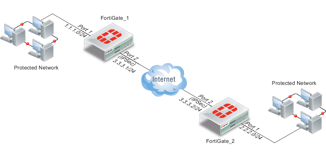
Example ports and IP addresses for offloaded IPsec processing
| FortiGate_1 | FortiGate_2 | |||
|---|---|---|---|---|
| Port | IP | Port | IP | |
| IPsec tunnel | FortiGate-5001B port 2 | 3.3.3.1/24 | FortiGate-5001B port 2 | 3.3.3.2/24 |
| Protected network | FortiGate-5001B port 1 | 1.1.1.0/24 | FortiGate-5001B port 1 | 2.2.2.0/24 |
Accelerated policy mode IPsec configuration
The following steps create a hardware accelerated policy mode IPsec tunnel between two FortiGate-5001B units, each containing two NP4 processors, the first of which will be used.
To configure hardware accelerated policy mode IPsec
- On FortiGate_1, go to VPN > IPsec > Auto Key (IKE).
- Configure Phase 1.
For tunnel mode IPsec and for hardware acceleration, specifying the Local Gateway IP is required.
Select Advanced. In the Local Gateway IP section, select Specify and type the VPN IP address 3.3.3.2, which is the IP address of FortiGate_2’s FortiGate-ASM-FB4 module port 2. - Configure Phase 2.
- Select Enable replay detection.
- Use the following command to enable offloading antireplay packets:
config system npu
set enc-offload-antireplay enable
end
For details on encryption and decryption offloading options available in the CLI, see"Configuring NP accelerated VPN encryption/decryption offloading".
- Go to Policy > Policy > Policy.
- Configure a policy to apply the Phase 1 IPsec tunnel you configured in step 2 to traffic between FortiGate-5001B ports 1 and 2.
- Go to Router > Static > Static Route.
- Configure a static route to route traffic destined for FortiGate_2’s protected network to VPN IP address of FortiGate_2’s VPN gateway, 3.3.3.2, through the FortiGate-5001B port2.
You can also configure the static route using the following CLI command:
config router static
edit 2
set device "AMC-SW1/2"
set dst 2.2.2.0 255.255.255.0
set gateway 3.3.3.2
end
- On FortiGate_2, go to VPN > IPsec > Auto Key (IKE).
- Configure Phase 1.
For tunnel mode IPsec and for hardware acceleration, specifying the Local Gateway IP is required.
Select Advanced. In the Local Gateway IP section, select Specify and type the VPN IP address 3.3.3.1, which is the IP address of FortiGate_1’s port2. - Configure Phase 2.
- Select Enable replay detection.
- Use the following command to enable offloading antireplay packets:
config system npu
set enc-offload-antireplay enable
end
For details on encryption and decryption offloading options available in the CLI, see Configuring NP accelerated IPsec VPN encryption/decryption offloading.
- Go to Policy > Policy > Policy.
- Configure a policy to apply the Phase 1 IPsec tunnel you configured in step 9 to traffic between FortiGate-5001B ports 1 and 2.
- Go to Router > Static > Static Route.
- Configure a static route to route traffic destined for FortiGate_1’s protected network to VPN IP address of FortiGate_1’s VPN gateway, 3.3.3.1, through the FortiGate-5001B port2.
You can also configure the static route using the following CLI commands:
config router static
edit 2
set device "AMC-SW1/2"
set dst 1.1.1.0 255.255.255.0
set gateway 3.3.3.1
end
- Activate the IPsec tunnel by sending traffic between the two protected networks.
To verify tunnel activation, go to VPN > Monitor > IPsec Monitor.
Accelerated interface mode IPsec configuration
The following steps create a hardware accelerated interface mode IPsec tunnel between two FortiGate units, each containing a FortiGate-ASM-FB4 module.
To configure hardware accelerated interface mode IPsec
- On FortiGate_1, go to VPN > IPsec > Auto Key (IKE).
- Configure Phase 1.
For interface mode IPsec and for hardware acceleration, the following settings are required.
- Select Advanced.
- Enable the checkbox “Enable IPsec Interface Mode.”
- In the Local Gateway IP section, select Specify and type the VPN IP address 3.3.3.2, which is the IP address of FortiGate_2’s port 2.
- Configure Phase 2.
- Select Enable replay detection.
- Use the following command to enable offloading antireplay packets:
config system npu
set enc-offload-antireplay enable
end
For details on encryption and decryption offloading options available in the CLI, see "Configuring NP accelerated VPN encryption/decryption offloading".
- Go to Policy > Policy > Policy.
- Configure two policies (one for each direction) to apply the Phase 1 IPsec configuration you configured in step 2 to traffic leaving from or arriving on FortiGate-ASM-FB4 module port 1.
- Go to Router > Static > Static Route.
- Configure a static route to route traffic destined for FortiGate_2’s protected network to the Phase 1 IPsec device, FGT_1_IPsec.
You can also configure the static route using the following CLI commands:
config router static
edit 2
set device "FGT_1_IPsec"
set dst 2.2.2.0 255.255.255.0
end
- On FortiGate_2, go to VPN > IPsec > Auto Key (IKE).
- Configure Phase 1.
For interface mode IPsec and for hardware acceleration, the following settings are required.
- Enable the checkbox “Enable IPsec Interface Mode.”
- In the Local Gateway IP section, select Specify and type the VPN IP address 3.3.3.1, which is the IP address of FortiGate_1’s FortiGate-5001B port 2.
- Configure Phase 2.
- Select Enable replay detection.
- Use the following command to enable offloading antireplay packets:
config system npu
set enc-offload-antireplay enable
end
For details on encryption and decryption offloading options available in the CLI, see Hardware acceleration overview.
- Go to Policy > Policy > Policy.
- Configure two policies (one for each direction) to apply the Phase 1 IPsec configuration you configured in step 9 to traffic leaving from or arriving on FortiGate-5001B port 1.
- Go to Router > Static > Static Route.
- Configure a static route to route traffic destined for FortiGate_1’s protected network to the Phase 1 IPsec device, FGT_2_IPsec.
You can also configure the static route using the following CLI commands:
config router static
edit 2
set device "FGT_2_IPsec"
set dst 1.1.1.0 255.255.255.0
next
end
- Activate the IPsec tunnel by sending traffic between the two protected networks.
To verify tunnel activation, go to VPN > Monitor > IPsec Monitor.
Configuring Inter-VDOM link acceleration with NP4 processors
FortiGate units with NP4 processors include inter-VDOM links that can be used to accelerate inter-VDOM link traffic.
|
|
Traffic is blocked if you enable IPS for traffic passing over inter-VDOM links if that traffic is being offloaded by an NP4 processor.If you disable NP4 offloading traffic will be allowed to flow. You can disable offloading in individual firewall policies by disabling auto-asic-offload for individual policies. You can also use the following command to disable all IPS offloadingconfig ips global set np-accel-mode {none | basic} set cp-accel-mode {none | basic | advanced} end |
- For a FortiGate unit with two NP4 processors there are also two inter-VDOM links, each with two interfaces:
- npu0-vlink:
npu0-vlink0
npu0-vlink1 - npu1-vlink:
npu1-vlink0
npu1-vlink1
These interfaces are visible from the GUI and CLI. For a FortiGate unit with NP4 interfaces, enter the following CLI command (output shown for a FortiGate-5001B):
get hardware npu np4 list
ID Model Slot Interface
0 On-board port1 port2 port3 port4
fabric1 base1 npu0-vlink0 npu0-vlink1
1 On-board port5 port6 port7 port8
fabric2 base2 npu1-vlink0 npu1-vlink1
By default the interfaces in each inter-VDOM link are assigned to the root VDOM. To use these interfaces to accelerate inter-VDOM link traffic, assign each interface in a pair to the VDOMs that you want to offload traffic between. For example, if you have added a VDOM named New-VDOM to a FortiGate unit with NP4 processors, you can go to System > Network > Interfaces and edit the npu0-vlink1 interface and set the Virtual Domain to New-VDOM.
This results in an inter-VDOM link between root and New-VDOM. You can also do this from the CLI:
config system interface
edit npu0-vlink1
set vdom New-VDOM
end
Using VLANs to add more accelerated Inter-VDOM links
You can add VLAN interfaces to the accelerated inter-VDOM links to create inter-VDOM links between more VDOMs. For the links to work, the VLAN interfaces must be added to the same inter-VDOM link, must be on the same subnet, and must have the same VLAN ID.
For example, to accelerate inter-VDOM link traffic between VDOMs named Marketing and Engineering using VLANs with VLAN ID 100 go to System > Network > Interfaces and select Create New to create the VLAN interface associated with the Marketing VDOM:
| Name | Marketing-link |
| Type | VLAN |
| Interface | npu0-vlink0 |
| VLAN ID | 100 |
| Virtual Domain | Marketing |
| IP/Network Mask | 172.20.120.12/24 |
Create the inter-VDOM link associated with Engineering VDOM:
| Name | Engineering-link |
| Type | VLAN |
| Interface | npu0-vlink1 |
| VLAN ID | 100 |
| Virtual Domain | Engineering |
| IP/Network Mask | 172.20.120.22/24 |
Or do the same from the CLI:
config system interface
edit Marketing-link
set vdom Marketing
set ip 172.20.120.12/24
set interface npu0-vlink0
set vlanid 100
next
edit Engineering-link
set vdom Engineering
set ip 172.20.120.22/24
set interface npu0-vlink1
set vlanid 100
Confirm that the traffic is accelerated
Use the following CLI commands to obtain the interface index and then correlate them with the session entries. In the following example traffic was flowing between new accelerated inter-VDOM links and physical ports port1 and port 2 also attached to the NP4 processor.
diagnose ip address list
IP=172.31.17.76->172.31.17.76/255.255.252.0 index=5 devname=port1
IP=10.74.1.76->10.74.1.76/255.255.252.0 index=6 devname=port2
IP=172.20.120.12->172.20.120.12/255.255.255.0 index=55 devname=IVL-VLAN1_ROOT
IP=172.20.120.22->172.20.120.22/255.255.255.0 index=56 devname=IVL-VLAN1_VDOM1
diagnose sys session list
session info: proto=1 proto_state=00 duration=282 expire=24 timeout=0 session info: proto=1 proto_state=00 duration=124 expire=59 timeout=0 flags=00000000 sockflag=00000000 sockport=0 av_idx=0 use=3
origin-shaper=
reply-shaper=
per_ip_shaper=
ha_id=0 policy_dir=0 tunnel=/
state=may_dirty npu
statistic(bytes/packets/allow_err): org=180/3/1 reply=120/2/1 tuples=2
orgin->sink: org pre->post, reply pre->post dev=55->5/5->55 gwy=172.31.19.254/172.20.120.22
hook=post dir=org act=snat 10.74.2.87:768->10.2.2.2:8(172.31.17.76:62464)
hook=pre dir=reply act=dnat 10.2.2.2:62464->172.31.17.76:0(10.74.2.87:768)
misc=0 policy_id=4 id_policy_id=0 auth_info=0 chk_client_info=0 vd=0
serial=0000004e tos=ff/ff ips_view=0 app_list=0 app=0
dd_type=0 dd_mode=0
per_ip_bandwidth meter: addr=10.74.2.87, bps=880
npu_state=00000000
npu info: flag=0x81/0x81, offload=4/4, ips_offload=0/0, epid=160/218, ipid=218/160, vlan=32769/0
session info: proto=1 proto_state=00 duration=124 expire=20 timeout=0 flags=00000000 sockflag=00000000 sockport=0 av_idx=0 use=3
origin-shaper=
reply-shaper=
per_ip_shaper=
ha_id=0 policy_dir=0 tunnel=/
state=may_dirty npu
statistic(bytes/packets/allow_err): org=180/3/1 reply=120/2/1 tuples=2
orgin->sink: org pre->post, reply pre->post dev=6->56/56->6 gwy=172.20.120.12/10.74.2.87
hook=pre dir=org act=noop 10.74.2.87:768->10.2.2.2:8(0.0.0.0:0)
hook=post dir=reply act=noop 10.2.2.2:768->10.74.2.87:0(0.0.0.0:0)
misc=0 policy_id=3 id_policy_id=0 auth_info=0 chk_client_info=0 vd=1
serial=0000004d tos=ff/ff ips_view=0 app_list=0 app=0
dd_type=0 dd_mode=0
per_ip_bandwidth meter: addr=10.74.2.87, bps=880
npu_state=00000000
npu info: flag=0x81/0x81, offload=4/4, ips_offload=0/0, epid=219/161, ipid=161/219, vlan=0/32769
total session 2
Offloading NP4 anomaly detection
Network interfaces associated with a port attached to an NP4 processor can be configured to offload anomaly checking to the NP4 processor. This anomaly checking happens before other offloading and separately from DoS policy anomaly checking. Using the following command, each FortiGate interface can have a different anomaly checking configuration even if they are connected to the same NP4 processor.
|
|
The options available for this command apply anomaly checking for NP4 sessions in the same way as the command descrbed in Configuring individual NP6 processors applies anomaly checking for for NP6 sessions. |
config system interface
edit <port-name>
set fp-anomaly <anomalies>
end
where <anomalies> can be one, more than one or all of the following:
| Anomaly | Description |
|---|---|
| drop_icmp_frag | Drop ICMP fragments to pass. |
| drop_icmpland | Drop ICMP Land. |
| drop_ipland | Drop IP Land. |
| drop_iplsrr | Drop IP with Loose Source Record Route option. |
| drop_iprr | Drop IP with Record Route option. |
| drop_ipsecurity | Drop IP with Security option. |
| drop_ipssrr | Drop IP with Strict Source Record Route option. |
| drop_ipstream | Drop IP with Stream option. |
| drop_iptimestamp | Drop IP with Timestamp option. |
| drop_ipunknown_option | Drop IP with malformed option. |
| drop_ipunknown_prot | Drop IP with Unknown protocol. |
| drop_tcp_fin_noack | Drop TCP FIN with no ACT flag set to pass. |
| drop_tcp_no_flag | Drop TCP with no flag set to pass. |
| drop_tcpland | Drop TCP Land. |
| drop_udpland | Drop UDP Land. |
| drop_winnuke | Drop TCP WinNuke. |
| pass_icmp_frag | Allow ICMP fragments to pass. |
| pass_icmpland | Allow ICMP Land to pass. |
| pass_ipland | Allow IP land to pass. |
| pass_iplsrr | Allow IP with Loose Source Record Route option to pass. |
| pass_iprr | Allow IP with Record Route option to pass. |
| pass_ipsecurity | Allow IP with Security option to pass. |
| pass_ipssrr | Allow IP with Strict Source Record Route option to pass. |
| pass_ipstream | Allow IP with Stream option to pass. |
| pass_iptimestamp | Allow IP with Timestamp option to pass. |
| pass_ipunknown_option | Allow IP with malformed option to pass. |
| pass_ipunknown_prot | Allow IP with Unknown protocol to pass. |
| pass_tcp_fin_noack | Allow TCP FIN with no ACT flag set to pass. |
| pass_tcp_no_flag | Allow TCP with no flag set to pass. |
| pass_tcpland | Allow TCP Land to pass. |
| pass_udpland | Allow UDP Land to pass. |
| pass_winnuke | Allow TCP WinNuke to pass. |
Example
You might configure an NP4 to drop packets with TCP WinNuke or unknown IP protocol anomalies, but to pass packets with an IP time stamp, using hardware acceleration provided by the network processor.
config system interface
edit port1
set fp-anomaly drop_winnuke drop_ipunknown_prot pass_iptimestamp
end
Copyright © 2018 Fortinet, Inc. All Rights Reserved. | Terms of Service | Privacy Policy
