
How to work with overlapping subnets
A site-to-site VPN configuration sometimes has the problem that the private subnet addresses at each end are the same. You can resolve this problem by remapping the private addresses using virtual IP addresses (VIP).
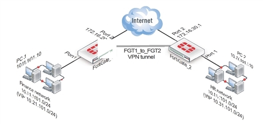
VIPs allow computers on those overlapping private subnets to each have another set of IP addresses that can be used without confusion. The FortiGate unit maps the VIP addresses to the original addresses. This means if PC1 starts a session with PC2 at 10.31.101.10, FortiGate_2 directs that session to 10.11.101.10 — the actual IP address of PC2.The figure below demonstrates this — Finance network VIP is 10.21.101.0/24 and the HR network is 10.31.101.0/24.
Overlapped subnets example
Solution for route-based VPN
You need to:
- Configure IPsec Phase 1 and Phase 2 as you usually would for a route-based VPN. In this example, the resulting IPsec interface is named
FGT1_to_FGT2. - Configure virtual IP (VIP) mapping:
- the 10.21.101.0/24 network mapped to the 10.11.101.0/24 network on FortiGate_1
- the 10.31.101.0/24 network mapped to the 10.11.101.0/24 network on FortiGate_2
- Configure an outgoing security policy with ordinary source NAT on both FortiGates.
- Configure an incoming security policy with the VIP as the destination on both FortiGates.
- Configure a route to the remote private network over the IPsec interface on both FortiGates.
To configure VIP mapping on both FortiGates
- Go to Policy & Objects > Objects > Virtual IPs and select Create New.
- Enter the following information, and select OK:
| Name | Enter a name, for example, my_vip. |
| External Interface | Select FGT1_to_FGT2. The IPsec interface. |
| Type | Static NAT |
| External IP Address/Range | For the External IP Address field enter:10.21.101.1 when configuring FortiGate_1, or 10.31.101.1 when configuring FortiGate_2. |
| Mapped IP Address/Range | For the Mapped IP Address enter 10.11.101.1.For the Range enter 10.11.101.254. |
| Port Forwarding | Disable |
- Repeat this procedure on both FortiGate_1 and FortiGate_2.
To configure the outbound security policy on both FortiGates
- Go to Policy & Objects > Policy > IPv4 and select Create New.
- Leave the Policy Type as Firewall and leave the Policy Subtype as Address.
- Enter the following information, and select OK:
| Incoming Interface | Select Port 1. |
| Source Address | Select all. |
| Outgoing Interface | Select FGT1_to_FGT2. The IPsec interface. |
| Destination Address | Select all. |
| Action | Select ACCEPT |
| Enable NAT | Enable |
- Repeat this procedure on both FortiGate_1 and FortiGate_2.
To configure the inbound security policy on both FortiGates
- Go to Policy & Objects > Policy > IPv4 and select Create New.
- Leave the Policy Type as Firewall and leave the Policy Subtype as Address.
- Enter the following information, and then select OK:
| Incoming Interface | Select FGT1_to_FGT2. |
| Source Address | Select all. |
| Outgoing Interface | Select Port 1. The IPsec interface. |
| Destination Address | Select my-vip. |
| Action | Select ACCEPT |
| Enable NAT | Disable |
- Repeat this procedure on both FortiGate_1 and FortiGate_2.
To configure the static route for both FortiGates
- Go to Router > Static > Static Routes and select Create New.
For low-end FortiGate units, go to System > Network > Routing and select Create New. - Enter the following information, and then select OK:
| Destination IP / Mask | Enter 10.31.101.0/24 when configuring FortiGate_1.Enter 10.21.101.0/24 when configuring FortiGate_2. |
| Device | Select FGT1_to_FGT2. |
| Gateway | Leave as default: 0.0.0.0. |
| Distance (Advanced) | Leave at default. If you have advanced routing on your network, you may have to change this value |
Solution for policy-based VPN
As with the route-based solution, users contact hosts at the other end of the VPN using an alternate subnet address. PC1 communicates with PC2 using IP address 10.31.101.10, and PC2 communicates with PC1 using IP address 10.21.101.10.
In this solution however, outbound NAT is used to translate the source address of packets from the 10.11.101.0/24 network to the alternate subnet address that hosts at the other end of the VPN use to reply. Inbound packets from the remote end have their destination addresses translated back to the 10.11.101.0/24 network.
For example, PC1 uses the destination address 10.31.101.10 to contact PC2. Outbound NAT on FortiGate_1 translates the PC1 source address to 10.21.101.10. At the FortiGate_2 end of the tunnel, the outbound NAT configuration translates the destination address to the actual PC2 address of 10.11.101.10. Similarly, PC2 replies to PC1 using destination address 10.21.101.10, with the PC2 source address translated to 10.31.101.10. PC1 and PC2 can communicate over the VPN even though they both have the same IP address.
- You need to:
- Configure IPsec Phase 1 as you usually would for a policy-based VPN.
- Configure IPsec Phase 2 with the
use-natip disableCLI option. - Define a firewall address for the local private network, 10.11.101.0/24.
- Define a firewall address for the remote private network:
- Define a firewall address for 10.31.101.0/24 on FortiGate_1
- Define a firewall address for 10.21.101.0/24 on FortiGate_2
- Configure an outgoing IPsec security policy with outbound NAT to map 10.11.101.0/24 source addresses:
- To the 10.21.101.0/24 network on FortiGate_1
- To the 10.31.101.0/24 network on FortiGate_2
To configure IPsec Phase 2 - CLI
config vpn ipsec phase2
edit "FGT1_FGT2_p2"
set keepalive enable
set pfs enable
set phase1name FGT1_to_FGT2
set proposal 3des-sha1 3des-md5
set replay enable
set use-natip disable
end
In this example, your Phase 1 definition is named FGT1_to_FGT2. use‑natip is set to disable, so you can specify the source selector using the src‑addr‑type, src-start-ip / src-end-ip or src-subnet keywords. This example leaves these keywords at their default values, which specify the subnet 0.0.0.0/0.
The pfs keyword ensures that perfect forward secrecy (PFS) is used. This ensures that each Phase 2 key created is unrelated to any other keys in use.
To define the local private network firewall address
- Go to Policy & Objects > Objects > Addresses and select Create New.
- Enter the following information and select OK.
| Name | Enter vpn-local. A meaningful name for the local private network. |
| Type | Subnet |
| Subnet / IP Range | 10.11.101.0 255.255.255.0 |
| Interface | Any |
To define the remote private network firewall address
- Go to Policy & Objects > Objects > Addresses and select Create New.
- Enter the following information, and select OK:
| Name | Enter vpn-remote. A meaningful name for the remote private network. |
| Type | Subnet |
| Subnet / IP Range | 10.31.101.0 255.255.255.0 on FortiGate_1.10.21.101.0 255.255.255.0 on FortiGate_2. |
| Interface | Any |
To configure the IPsec security policy
In the CLI on FortiGate_1, enter the commands:
config firewall policy
edit 1
set srcintf "port1"
set dstintf "port2"
set srcaddr "vpn-local"
set dstaddr "vpn-remote"
set action ipsec
set schedule "always"
set service "ANY"
set inbound enable
set outbound enable
set vpntunnel "FGT1_to_FGT2"
set natoutbound enable
set natip 10.31.101.0 255.255.255.0
end
Optionally, you can set everything except natip in the web-based manager and then use the CLI to set natip.
Enter the same commands on FortiGate_2, but set natip be 10.21.101.0 255.255.255.0.
Copyright © 2018 Fortinet, Inc. All Rights Reserved. | Terms of Service | Privacy Policy
