
Interfaces
Interfaces, both physical and virtual, enable traffic to flow to and from the internal network, and the Internet and between internal networks. The FortiGate unit has a number of options for setting up interfaces and groupings of subnetworks that can scale to a company’s growing requirements.
This chapter includes:
- Physical
- Interface settings
- Software switch
- Virtual Switch
- Loopback interfaces
- Redundant interfaces
- One-armed sniffer
- Aggregate Interfaces
- DHCP addressing mode on an interface
- Administrative access
- Wireless
- Interface MTU packet size
- Secondary IP addresses to an interface
- Virtual domains
- Virtual LANs
- Zones
Physical
FortiGate units have a number of physical ports where you connect ethernet or optical cables. Depending on the model, they can have anywhere from four to 40 physical ports. Some units have a grouping of ports labelled as internal, providing a built-in switch functionality.
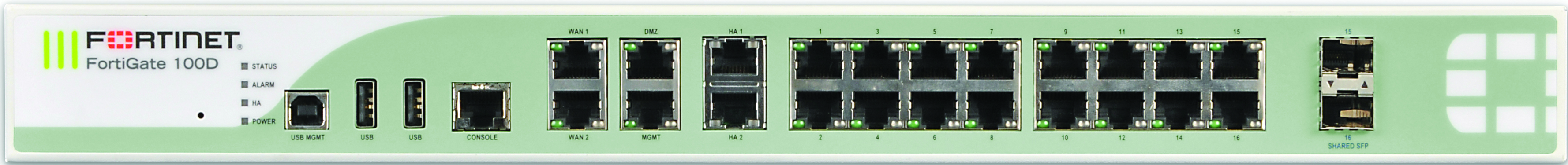
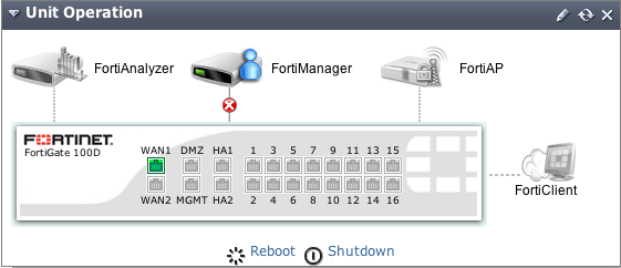
In FortiOS, the port names, as labeled on the FortiGate unit, appear in the web-based manager in the Unit Operation widget, found on the Dashboard. They also appear when you are configuring the interfaces, by going to System > Network > Interface. As shown below, the FortiGate‑100D (Generation 2) has 22 interfaces.
|
|
Two of the physical ports on the FortiGate-100D (Generation 2) are SFP ports. These ports share the numbers 15 and 16 with RJ-45 ports. Because of this, when SFP port 15 is used, RJ-45 port 15 cannot be used, and vice versa. These ports also share the same MAC address. |
FortiGate-100D physical interfaces
FortiGate-100D interfaces on the Dashboard
Configuring the FortiGate-100D ports
Normally the internal interface is configured as a single interface shared by all physical interface connections - a switch. The switch mode feature has two states - switch mode and interface mode. Switch mode is the default mode with only one interface and one address for the entire internal switch. Interface mode enables you to configure each of the internal switch physical interface connections separately. This enables you to assign different subnets and netmasks to each of the internal physical interface connections.
The larger FortiGate units can also include Advanced Mezzanine Cards (AMC), which can provide additional interfaces (Ethernet or optical), with throughput enhancements for more efficient handling of specialized traffic. These interfaces appear in FortiOS as port amc/sw1, amc/sw2 and so on. In the following illustration, the FortiGate‑3810A has three AMC cards installed: two single-width (amc/sw1, amc/sw2) and one double-width (amc/dw).
FortiGate-3810A AMC card port naming
Interface settings
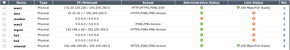
In System > Network > Interface, you configure the interfaces, physical and virtual, for the FortiGate unit. There are different options for configuring interfaces when the FortiGate unit is in NAT mode or transparent mode. On FortiOS Carrier, you can also enable the Gi gatekeeper on each interface for anti-overbilling.
| Interface page | |
|---|---|
| Create New | Select to add a new interface, zone or, in transparent mode, port pair. For more information on configuring zones, see Zones. Depending on the model you can add a VLAN interface, a loopback interface, a IEEE 802.3ad aggregated interface, or a redundant interface. When VDOMs are enabled, you can also add Inter-VDOM links. |
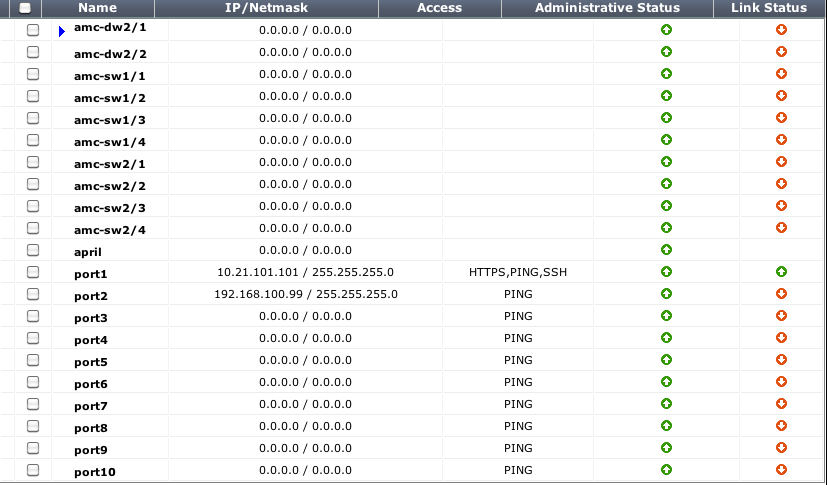
| Name | The names of the physical interfaces on your FortiGate unit. This includes any alias names that have been configured. When you combine several interfaces into an aggregate or redundant interface, only the aggregate or redundant interface is listed, not the component interfaces. If you have added VLAN interfaces, they also appear in the name list, below the physical or aggregated interface to which they have been added. If you have added loopback interfaces, they also appear in the interface list, below the physical interface to which they have been added. If you have software switch interfaces configured, you will be able to view them. If your FortiGate unit supports AMC modules, the interfaces are named amc-sw1/1, amc-dw1/2, and so on. |
| Type | The configuration type for the interface. |
| IP/Netmask | The current IP address and netmask of the interface. In VDOM, when VDOMs are not all in NAT or transparent mode some values may not be available for display and will be displayed as “-”. |
| Access | The administrative access configuration for the interface. |
| Administrative Status | Indicates if the interface can be accessed for administrative purposes. If the administrative status is a green arrow, and administrator could connect to the interface using the configured access. If the administrative status is a red arrow, the interface is administratively down and cannot be accessed for administrative purposes. |
| Link Status | The status of the interface physical connection. Link status can be either up (green arrow) or down (red arrow). If link status is up the interface is connected to the network and accepting traffic. If link status is down the interface is not connected to the network or there is a problem with the connection. You cannot change link status from the web-based manager, and typically is indicative of an ethernet cable plugged into the interface. Link status is only displayed for physical interfaces. |
| MAC | The MAC address of the interface. |
| Mode | Shows the addressing mode of the interface. The addressing mode can be manual, DHCP, or PPPoE. |
| Secondary IP | Displays the secondary IP addresses added to the interface. |
| MTU | The maximum number of bytes per transmission unit (MTU) for the interface. |
| Virtual Domain | The virtual domain to which the interface belongs. This column is visible when VDOM configuration is enabled. |
| VLAN ID | The configured VLAN ID for VLAN subinterfaces. |
Interface configuration and settings
To configure an interface, go to System > Network > Interface and select Create New.
| Name | Enter a name of the interface. Physical interface names cannot be changed. | |
| Alias | Enter an alternate name for a physical interface on the FortiGate unit. This field appears when editing an existing physical interface. The alias can be a maximum of 25 characters. The alias name will not appears in logs. |
|
| Link Status | Indicates whether the interface is connected to a network (link status is Up) or not (link status is Down). This field appears when editing an existing physical interface. | |
| Type | Select the type of interface that you want to add. On some models you can set Type to 802.3ad Aggregate or Redundant Interface. |
|
| Interface | Displayed when Type is set to VLAN. Select the name of the physical interface to which to add a VLAN interface. Once created, the VLAN interface is listed below its physical interface in the Interface list. You cannot change the physical interface of a VLAN interface except when adding a new VLAN interface. |
|
| VLAN ID | Displayed when Type is set to VLAN. Enter the VLAN ID. You cannot change the VLAN ID except when adding a new VLAN interface. The VLAN ID can be any number between 1 and 4094 and must match the VLAN ID added by the IEEE 802.1Q-compliant router or switch connected to the VLAN subinterface. |
|
| Virtual Domain | Select the virtual domain to add the interface to. Admin accounts with super_admin profile can change the Virtual Domain. |
|
| Physical Interface Members | This section has two different forms depending on the interface type: • Software switch interface - this section is a display-only field showing the interfaces that belong to the software switch virtual interface. • 802.3ad aggregate or Redundant interface - this section includes available interface and selected interface lists to enable adding or removing interfaces from the interface. Select interfaces from this Available Interfaces list and select the right arrow to add an interface to the Selected Interface list. |
|
| Addressing mode | Select the addressing mode for the interface. • Select Manual and add an IP/Netmask for the interface. If IPv6 configuration is enabled you can add both a IPv4 and an IPv6 IP address. • Select DHCP to get the interface IP address and other network settings from a DHCP server. • Select PPPoE to get the interface IP address and other network settings from a PPPoE server. • Select One-Arm Sniffer to enable the interface as a means to detect possible traffic threats. This option is available on physical ports not configured for the primary Internet connection. • Select Dedicate to FortiAP/FortiSwitch to have a FortiAP unit or FortiSwitch unit connect exclusively to the interface. This option is only available when editing a physical interface, and it has a static IP address. When you enter the IP address, the FortiGate unit automatically creates a DHCP server using the subnet entered. This option is not available on the ADSL interface. The FortiSwitch option is currently only available on the FortiGate-100D. |
|
| IP/Netmask | If Addressing Mode is set to Manual, enter an IPv4 address/subnet mask for the interface. FortiGate interfaces cannot have IP addresses on the same subnet. | |
| IPv6 Address | If Addressing Mode is set to Manual and IPv6 support is enabled, enter an IPv6 address/subnet mask for the interface. A single interface can have both an IPv4 and IPv6 address or just one or the other. | |
| Administrative Access | Select the types of administrative access permitted for IPv4 connections to this interface. | |
| HTTPS | Allow secure HTTPS connections to the web‑based manager through this interface. If configured, this option will enable automatically when selecting the HTTP option. | |
| PING | Interface responds to pings. Use this setting to verify your installation and for testing. | |
| HTTP | Allow HTTP connections to the web‑based manager through this interface. If configured, this option will also enable the HTTPS option. | |
| SSH | Allow SSH connections to the CLI through this interface. | |
| SNMP | Allow a remote SNMP manager to request SNMP information by connecting to this interface. | |
| TELNET | Allow Telnet connections to the CLI through this interface. Telnet connections are not secure and can be intercepted by a third party. | |
| FMG-Access | Allow FortiManager authorization automatically during the communication exchange between the FortiManager and FortiGate units. | |
| FCT-Access | You can configure a FortiGate interface as an interface that will accept FortiClient connections. When configured, the FortiGate unit sends broadcast messages which the FortiClient software running on a end user PC is listening for. | |
| CAPWAP | Allows the FortiGate unit’s wireless controller to manage a wireless access point, such as a FortiAP unit. | |
| IPv6 Administrative Access | Select the types of administrative access permitted for IPv6 connections to this interface. These types are the same as for Administrative Access. | |
| Security Mode | Select a captive portal for the interface. When selected, you can define the portal message and look that the user sees when logging into the interface. You can also define one or more user groups that have access to the interface. | |
| DHCP Server | Select to enable a DHCP server for the interface. For more information on configuring a DHCP server on the interface, see DHCP servers and relays. | |
| Detect and Identify Devices | Select to enable the interface to be used with BYOD hardware such as iPhones. Define the device definitions by going to User & Device > Device. | |
| Add New Devices to Vulnerability Scan List | This option appears when Detect and Identify Devices is enabled. When enabled, the FortiGate unit performs a network vulnerability scan of any devices detected or seen on the interface. The vulnerability scan occur as configured, either on demand, or as scheduled. | |
| Broadcast Discovery Messages | Available when FCT-Access is enabled for the Administrative Access. Select to enable sends broadcast messages which the FortiClient software running on a end user PC is listening for. Once enabled, the FortiGate unit broadcasts a discovery message that includes the IP address of the interface and listening port number to the local network. All PCs running FortiClient on that network listen for this discovery message. |
|
| Enable Explicit Web Proxy | Available when enabling explicit proxy on the System Information Dashboard (System > Dashboard > Status). This option is not available for a VLAN interface selection. Select to enable explicit web proxying on this interface. When enabled, this interface will be displayed on System > Network > Explicit Proxy under Listen on Interfaces and web traffic on this interface will be proxied according to the Web Proxy settings. |
|
| Enable STP | With FortiGate units with a switch interface is in switch mode, this option is enabled by default. It enables the single instance MSTP spanning tree protocol. | |
| Listen for RADIUS Accounting Messages | Select to use the interface as a listening port for RADIUS content. | |
| Secondary IP Address | Add additional IPv4 addresses to this interface. Select the Expand Arrow to expand or hide the section. | |
| Comments | Enter a description up to 255 characters to describe the interface. | |
| Administrative Status | Select either Up (green arrow) or Down (red arrow) as the status of this interface. Up indicates the interface is active and can accept network traffic. Down indicates the interface is not active and cannot accept traffic. |
|
| Gi Gatekeeper (FortiOS Carrier only) | For FortiOS Carrier, enable Gi Gatekeeper to enable the Gi firewall as part of the anti-overbilling configuration. You must also configure Gi Gatekeeper Settings by going to System > Admin > Settings. | |
Software switch
A software switch, or soft switch, is a virtual switch that is implemented at the software, or firmware level, rather than the hardware level. A software switch can be used to simplify communication between devices connected to different FortiGate interfaces. For example, using a software switch, you can place the FortiGate interface connected to an internal network on the same subnet as your wireless interfaces. Then devices on the internal network can communicate with devices on the wireless network without any additional configuration such as additional security policies, on the FortiGate unit.
It can also be useful if you require more hardware ports on for the switch on a FortiGate unit. For example, if your FortiGate unit has a 4-port switch, WAN1, WAN2 and DMZ interfaces, and you need one more port, you can create a soft switch that can include the 4-port switch and the DMZ interface all on the same subnet. These types of applications also apply to wireless interfaces and virtual wireless interfaces and physical interfaces such as those with FortiWiFi and FortiAP unit.
Similar to a hardware switch, a software switch functions like a single interface. A software switch has one IP address; all of the interfaces in the software switch are on the same subnet. Traffic between devices connected to each interface are not regulated by security policies, and traffic passing in and out of the switch are affected by the same policy.
There are a few things to consider when setting up a software switch:
- Ensure you create a back up of the configuration.
- Ensure you have at least one port or connection such as the console port to connect to the FortiGate unit. If you accidentally combine too many ports, you will need a way to undo any errors.
- The ports that you include must not have any link or relation to any other aspect of the FortiGate unit. For example, DHCP servers, security policies, and so on.
- For increased security, you can create a captive portal for the switch, allowing only specific user groups access to the resources connected to the switch.
To create a software switch - web-based manager
- Go to System > Network > Interface and select Create New.
- For Type, select Software Switch.
- In the Physical Interface Members option, select the interfaces to include.
- Configure the remaining interface settings
- Select OK.
To create a software switch - CLI
config system switch-interface
edit <switch-name>
set type switch
set member <interface_list>
end
config system interface
edit <switch_name>
set ip <ip_address>
set allowaccess https ssh ping
end
Soft switch example
For this example, the wireless interface (WiFi) needs to be on the same subnet as the DMZ1 interface to facilitate wireless syncing from an iPhone and a local computer. The synching between two subnets is problematic. By putting both interfaces on the same subnet the synching will work. The software switch will accomplish this.
|
|
In this example, the soft switch includes a wireless interface. Remember to configure any wireless security before proceeding. If you leave this interface open without any password or other security, it leaves open access to not only the wireless interface but to any other interfaces and devices connected within the software switch. |
Clear the interfaces and back up the configuration
First, ensure that the interfaces are not being used with any other security policy or other use on the FortiGate unit. Check the WiFi and DMZ1 ports to ensure DHCP is not enabled on the interface and there are no other dependencies with these interfaces.
Next, save the current configuration, in the event something doesn’t work, recovery can be quick.
Merge the interfaces
The plan is to merge the WiFi port and DMZ1 port. This will create a software switch with a name of “synchro” with an IP address of 10.10.21.12. The steps will create the switch, add the IP and then set the administrative access for HTTPS, SSH and Ping.
To merge the interfaces - CLI
config system switch-interface
edit synchro
set type switch
set member dmz1 wifi
end
config system interface
edit synchro
set ip 10.10.21.12
set allowaccess https ssh ping
end
Final steps
With the switch set up, you can now add security policies, DHCP servers an any other configuration that you would normally do to configure interfaces on the FortiGate unit.
Virtual Switch
Virtual switch feature enables you create virtual switches on top of the physical switch(es) with designated interfaces/ports so that a virtual switch can build up its forwarding table through learning and forward traffic accordingly. When traffic is forwarded among interfaces belonging to the same virtual switch, the traffic doesn't need to go up to the software stack, but forwarded directly by the switch. When traffic has to be relayed to interfaces not on the virtual switch, the traffic will go through the normal data path and be offloaded to NP4 when possible.
This feature is only available on mid to high end FortiGate units, including the 100D, 600C, 1000C, and 1240B.
To enable and configure the virtual switch, enter the CLI commands:
config system virtual-switch
edit vs1
set physical-switch sw0
config port
edit 1
set port port1
set speed xx
set duplex xx
set status [up|down]
edit 2
set port port2
set ...
end
end
end
Loopback interfaces
A loopback interface is a logical interface that is always up (no physical link dependency) and the attached subnet is always present in the routing table.
The FortiGate's loopback IP address does not depend on one specific external port, and is therefore possible to access it through several physical or VLAN interfaces. Multiple loopback interfaces can be configured in either non-VDOM mode or in each VDOM.
Loopback interfaces still require appropriate firewall policies to allow traffic to and from this type of interface.
A loopback interface can be used with:
- Management access
- BGP (TCP) peering
- PIM RP
Loopback interfaces are a good practice for OSPF. Setting the OSPF router ID the same as loopback IP address troubleshooting OSPF easier, and remembering the management IP addresses (telnet to “router ID”).
Dynamic routing protocols can be enabled on loopback interfaces
For black hole static route, use the black hole route type instead of the loopback interface.
Redundant interfaces
On some models you can combine two or more physical interfaces to provide link redundancy. This feature enables you to connect to two or more switches to ensure connectivity in the event one physical interface or the equipment on that interface fails.
In a redundant interface, traffic is only going over one interface at any time. This differs from an aggregated interface where traffic is going over all interfaces for distribution of increased bandwidth. This difference means redundant interfaces can have more robust configurations with fewer possible points of failure. This is important in a fully-meshed HA configuration.
An interface is available to be in a redundant interface if:
- it is a physical interface, not a VLAN interface
- it is not already part of an aggregated or redundant interface
- it is in the same VDOM as the redundant interface
- it has no defined IP address
- is not configured for DHCP or PPPoE
- it has no DHCP server or relay configured on it
- it does not have any VLAN subinterfaces
- it is not referenced in any security policy, VIP, or multicast policy
- it is not monitored by HA
- it is not one of the FortiGate-5000 series backplane interfaces
When an interface is included in a redundant interface, it is not listed on the System > Network > Interface page. You cannot configure the interface individually and it is not available for inclusion in security policies, VIPs, or routing.
One-armed sniffer
A one-armed sniffer is used to configure a physical interface on the FortiGate unit as a one-arm intrusion detection system (IDS). Traffic sent to the interface is examined for matches to the configured IPS sensor and application control list. Matches are logged and then all received traffic is dropped. Sniffing only reports on attacks. It does not deny or otherwise influence traffic.
Using the one-arm sniffer, you can configure a FortiGate unit to operate as an IDS appliance by sniffing network traffic for attacks without actually processing the packets. To configure one-arm IDS, you enable sniffer mode on a FortiGate interface and connect the interface to a hub or to the SPAN port of a switch that is processing network traffic.
To assign an interface as a sniffer interface, go to System > Network > Interface, edit the interface and select One-Arm Sniffer.
If the check box is not available, the interface is in use. Ensure that the interface is not selected in any firewall policies, routes, virtual IPs or other features in which a physical interface is specified.
| Enable Filters | Select to include filters to define a more granular sniff of network traffic. Select specific addresses, ports, VLANs and protocols. In all cases, enter a number, or number range, for the filtering type. For Protocol values, standard protocols are: • UDP - 17 • TCP - 6 • ICMP - 1 |
| Include IPv6 Packets | If your network is running a combination of IPv4 and IPv6 addressing, select to sniff both addressing types. Otherwise, the FortiGate unit will only sniff IPv4 traffic. |
| Include Non-IP Packets | Select for a more intense scan of content in the traffic. |
| UTM Security Profiles | IPS sensors, and application control lists enable you to select specific sensors and application you want to identify within the traffic. |
Aggregate Interfaces
Link aggregation (IEEE 802.3ad) enables you to bind two or more physical interfaces together to form an aggregated (combined) link. This new link has the bandwidth of all the links combined. If a link in the group fails, traffic is transferred automatically to the remaining interfaces with the only noticeable effect being a reduced bandwidth.
This is similar to redundant interfaces with the major difference being that a redundant interface group only uses one link at a time, where an aggregate link group uses the total bandwidth of the functioning links in the group, up to eight (or more).
Support of the IEEE standard 802.3ad for link aggregation is available on some models.
An interface is available to be an aggregate interface if:
- it is a physical interface, not a VLAN interface or subinterface
- it is not already part of an aggregate or redundant interface
- it is in the same VDOM as the aggregated interface. Aggregate ports cannot span multiple VDOMs.
- it does not have an IP address and is not configured for DHCP or PPPoE
- it is not referenced in any security policy, VIP, IP Pool or multicast policy
- it is not an HA heartbeat interface
- it is not one of the FortiGate-5000 series backplane interfaces
Some models of FortiGate units do not support aggregate interfaces. In this case, the aggregate option is not an option in the web-based manager or CLI. As well, you cannot create aggregate interfaces from the interfaces in a switch port.
To see if a port is being used or has other dependencies, use the following diagnose command:
diagnose sys checkused system.interface.name <interface_name>
When an interface is included in an aggregate interface, it is not listed on the System > Network > Interface page. Interfaces will still appear in the CLI, although configuration for those interfaces will not take affect. You cannot configure the interface individually and it is not available for inclusion in security policies, VIPs, IP pools, or routing.
Example
This example creates an aggregate interface on a FortiGate-3810A using ports 4-6 with an internal IP address of 10.13.101.100, as well as the administrative access to HTTPS and SSH.
To create an aggregate interface - web-based manager
- Go to System > Network > Interface and select Create New.
- Enter the Name as
Aggregate. - For the Type, select 802.3ad Aggregate.
If this option does not appear, your FortiGate unit does not support aggregate interfaces.
- In the Available Interfaces list, select port 4, 5 and 6 and move it to the Selected Interfaces list.
- Select the Addressing Mode of Manual.
- Enter the IP address for the port of 10.13.101.100/24.
- For Administrative Access select HTTPS and SSH.
- Select OK.
To create aggregate interface - CLI
config system interface
edit Aggregate
set type aggregate
set member port4 port5 port6
set vdom root
set ip 172.20.120.100/24
set allowaccess https ssh
end
DHCP addressing mode on an interface
If you configure an interface to use DHCP, the FortiGate unit automatically broadcasts a DHCP request from the interface. The interface is configured with the IP address and any DNS server addresses and default gateway address that the DHCP server provides.
|
|
DHCP IPv6 is similar to DHCP IPv4, however there is: • no default gateway option defined because a host learns the gateway using router advertisement messages • there is no WINS servers because it is obsolete. For more information about DHCP IPv6, see RFC 3315. |
Configure DHCP for an interface in System > Network > Interface and selecting the interface from the list, and selecting DHCP in the Address Mode. The table describes the DHCP status information when DHCP is configured for an interface.
| Addressing mode section of New Interface page for DHCP informatio | ||
|---|---|---|
| Status | Displays DHCP status messages as the interface connects to the DHCP server and gets addressing information. Select Status to refresh the addressing mode status message. Status can be one of: • initializing - No activity. • connecting - interface attempts to connect to the DHCP server. • connected - interface retrieves an IP address, netmask, and other settings from the DHCP server. • failed - interface was unable to retrieve an IP address and other settings from the DHCP server. |
|
| Obtained IP/Netmask | The IP address and netmask leased from the DHCP server. Only displayed if Status is connected. | |
| Renew | Select to renew the DHCP license for this interface. Only displayed if Status is connected. | |
| Expiry Date | The time and date when the leased IP address and netmask is no longer valid for the interface. The IP address is returned to the pool to be allocated to the next user request for an IP address. Only displayed if Status is connected. | |
| Default Gateway | The IP address of the gateway defined by the DHCP server. Only displayed if Status is connected, and if Receive default gateway from server is selected. | |
| Distance | Enter the administrative distance for the default gateway retrieved from the DHCP server. The administrative distance, an integer from 1‑255, specifies the relative priority of a route when there are multiple routes to the same destination. A lower administrative distance indicates a more preferred route. | |
| Retrieve default gateway from server | Enable to retrieve a default gateway IP address from the DHCP server. The default gateway is added to the static routing table. | |
| Override internal DNS | Enable to use the DNS addresses retrieved from the DHCP server instead of the DNS server IP addresses on the DNS page. When VDOMs are enabled, you can override the internal DNS only on the management VDOM. |
|
PPPoE addressing mode on an interface
If you configure the interface to use PPPoE, the FortiGate unit automatically broadcasts a PPPoE request from the interface.
The FortiGate units support many PPPoE RFC features (RFC 2516) including unnumbered IPs, initial discovery timeout and PPPoE Active Discovery Terminate (PADT).
PPPoE is only configurable in the web-based manager on desktop FortiGate units. 1U FortiGates and up must be configured in the CLI using the commands:
config system interface
edit <port_name>
set mode pppoe
set username <ISP_username>
set password <ISP_password>
set idle-timeout <seconds>
set distance <integer>
set ipunnumbered <unumbered-IP>
set disc-retry-timeout <seconds>
set padt-retry-timeout <seconds>
set lcp-echo-interval <seconds>
set dns-server-override {enable | disable}
end
Configure PPPoE on an interface in System > Network > Interface. The table describes the PPPoE status information when PPPoE is configured for an interface.
| Addressing mode section of New Interface page | ||
|---|---|---|
| Status | Displays PPPoE status messages as the FortiGate unit connects to the PPPoE server and gets addressing information. Select Status to refresh the addressing mode status message. The status is only displayed if you selected Edit. Status can be any one of the following 4 messages. |
|
| Initializing | No activity. | |
| Connecting | The interface is attempting to connect to the PPPoE server. | |
| Connected | The interface retrieves an IP address, netmask, and other settings from the PPPoE server. When the status is connected, PPPoE connection information is displayed. |
|
| Failed | The interface was unable to retrieve an IP address and other information from the PPPoE server. | |
| Reconnect | Select to reconnect to the PPPoE server. Only displayed if Status is connected. |
|
| User Name | The PPPoE account user name. | |
| Password | The PPPoE account password. | |
| Unnumbered IP | Specify the IP address for the interface. If your ISP has assigned you a block of IP addresses, use one of them. Otherwise, this IP address can be the same as the IP address of another interface or can be any IP address. | |
| Initial Disc Timeout | Enter Initial discovery timeout. Enter the time to wait before starting to retry a PPPoE discovery. | |
| Initial PADT timeout | Enter Initial PPPoE Active Discovery Terminate (PADT) timeout in seconds. Use this timeout to shut down the PPPoE session if it is idle for this number of seconds. PADT must be supported by your ISP. Set initial PADT timeout to 0 to disable. | |
| Distance | Enter the administrative distance for the default gateway retrieved from the PPPoE server. The administrative distance, an integer from 1‑255, specifies the relative priority of a route when there are multiple routes to the same destination. A lower administrative distance indicates a more preferred route. The default distance for the default gateway is 1. | |
| Retrieve default gateway from server | Enable to retrieve a default gateway IP address from a PPPoE server. The default gateway is added to the static routing table. | |
| Override internal DNS | Enable to replace the DNS server IP addresses on the System DNS page with the DNS addresses retrieved from the PPPoE server. When VDOMs are enabled, you can override the internal DNS only on the management VDOM. |
|
Administrative access
Interfaces, especially the public-facing ports can be potentially accessed by those who you may not want access to the FortiGate unit. When setting up the FortiGate unit, you can set the type of protocol an administrator must use to access the FortiGate unit. The options include:
- HTTPS
- HTTP
- SSH
- TELNET
- SNMP
- PING
- FortiManager Access (FMG-Access)
- FortiClient Access (FCT-Access)
You can select as many, or as few, even none, that are accessible by an administrator.
This example adds an IPv4 address 172.20.120.100 to the WAN1 interface as well as the administrative access to HTTPS and SSH. As a good practice, set the administrative access when you are setting the IP address for the port.
To add an IP address on the WAN1 interface - web-based manager
- Go to System > Network > Interface.
- Select the WAN1 interface row and select Edit.
- Select the Addressing Mode of Manual.
- Enter the IP address for the port of 172.20.120.100/24.
- For Administrative Access, select HTTPS and SSH.
- Select OK.
To create IP address on the WAN1 interface - CLI
config system interface
edit wan1
set ip 172.20.120.100/24
set allowaccess https ssh
end
|
|
When adding to, or removing a protocol, you must type the entire list again. For example, if you have an access list of HTTPS and SSH, and you want to add PING, typing:set allowaccess ping...only PING will be set. In this case, you must type... set allowaccess https ssh ping |
Wireless
A wireless interface is similar to a physical interface only it does not include a physical connection. The FortiWiFi units enables you to add multiple wireless interfaces that can be available at the same time (the FortiWiFi-30B can only have one wireless interface). On FortiWiFi units, you can configure the device to be either an access point, or a wireless client. As an access point, the FortiWiFi unit can have up to four separate SSIDs, each on their own subnet for wireless access. In client mode, the FortiWiFi only has one SSID, and is used as a receiver, to enable remote users to connect to the existing network using wireless protocols.
Wireless interfaces also require additional security measures to ensure the signal does not get hijacked and data tampered or stolen.
For more information on configuring wireless interfaces see the Deploying Wireless Networks Guide.
Interface MTU packet size
You can change the maximum transmission unit (MTU) of the packets that the FortiGate unit transmits to improve network performance. Ideally, the MTU should be the same as the smallest MTU of all the networks between the FortiGate unit and the destination of the packets. If the packets that the FortiGate unit sends are larger than the smallest MTU, they are broken up or fragmented, which slows down transmission. You can easily experiment by lowering the MTU to find an MTU size for optimum network performance.
To change the MTU, select Override default MTU value (1500) and enter the MTU size based on the addressing mode of the interface
- 68 to 1 500 bytes for static mode
- 576 to 1 500 bytes for DHCP mode
- 576 to 1 492 bytes for PPPoE mode
- larger frame sizes if supported by the FortiGate model - up to 9216 bytes for NP2, NP4, and NP6-accelerated interfaces
Only available on physical interfaces. Virtual interfaces associated with a physical interface inherit the physical interface MTU size.
Interfaces on some models support frames larger than the traditional 1500 bytes. Jumbo frames are supported on FortiGate models that have either a SOC2 or NP4lite, except for the FortiGate-30D, as well as on FortiGate-100D series models (for information about your FortiGate unit’s hardware, see the Hardware Acceleration guide). For other models, please contact Fortinet Customer Support for the maximum frame size that is supported.
If you need to enable sending larger frames over a route, you need all Ethernet devices on that route to support that larger frame size, otherwise your larger frames will not be recognized and are dropped.
If you have standard size and larger size frame traffic on the same interface, routing alone cannot route them to different routes based only on frame size. However, you can use VLANs to make sure the larger frame traffic is routed over network devices that support that larger size. VLANs will inherit the MTU size from the parent interface. You will need to configure the VLAN to include both ends of the route as well as all switches and routers along the route.
MTU packet size is changed in the CLI. If you select an MTU size larger than your FortiGate unit supports, an error message will indicate this. In this situation, try a smaller MTU size until the value is supported.
|
|
In Transparent mode, if you change the MTU of an interface, you must change the MTU of all interfaces on the FortiGate unit to match the new MTU. |
To change the MTU size, use the following CLI commands:
config system interface
edit <interface_name>
set mtu-override enable
set mtu <byte_size>
end
Secondary IP addresses to an interface
If an interface is configured with a manual or static IP address, you can also add secondary static IP addresses to the interface. Adding secondary IP addresses effectively adds multiple IP addresses to the interface. Secondary IP addresses cannot be assigned using DCHP or PPPoE.
All of the IP addresses added to an interface are associated with the single MAC address of the physical interface and all secondary IP addresses are in the same VDOM as the interface that are added to. You configure interface status detection for gateway load balancing separately for each secondary IP addresses. As with all other interface IP addresses, secondary IP addresses cannot be on the same subnet as any other primary or secondary IP address assigned to a FortiGate interface unless they are in separate VDOMs.
To configure a secondary IP, go to System > Network > Interface, select Edit or Create New and select the Secondary IP Address check box.
Virtual domains
Virtual domains (VDOMs) are a method of dividing a FortiGate unit into two or more virtual units that function as multiple independent units. A single FortiGate unit is then flexible enough to serve multiple departments of an organization, separate organizations, or to act as the basis for a service provider’s managed security service.
VDOMs provide separate security domains that allow separate zones, user authentication, security policies, routing, and VPN configurations. By default, each FortiGate unit has a VDOM named root. This VDOM includes all of the FortiGate physical interfaces, modem, VLAN subinterfaces, zones, security policies, routing settings, and VPN settings.
When a packet enters a VDOM, it is confined to that VDOM. In a VDOM, you can create security policies for connections between Virtual LAN (VLAN) subinterfaces or zones in the VDOM. Packets do not cross the virtual domain border internally. To travel between VDOMs, a packet must pass through a firewall on a physical interface. The packet then arrives at another VDOM on a different interface, but it must pass through another firewall before entering the VDOM Both VDOMs are on the same FortiGate unit. Inter-VDOMs change this behavior in that they are internal interfaces; however their packets go through all the same security measures as on physical interfaces.
This example shows how to enable VDOMs on the FortiGate unit and the basic and create a VDOM accounting on the DMZ2 port and assign an administrator to maintain the VDOM. First enable Virtual Domains on the FortiGate unit. When you enable VDOMs, the FortiGate unit will log you out.
For desktop and low-end FortiGate units, VDOMs are enabled using the CLI. On larger FortiGate units, you can enable on the web-based manager or the CLI. Once enabled all further configuration can be made in the web-based manager or CLI.
To enable VDOMs - web-based manager
- Go to System > Dashboard > Status.
- In the System Information widget, select Enable for Virtual Domain.
The FortiGate unit logs you out. Once you log back in, you will notice that the menu structure has changed. This reflects the global settings for all Virtual Domains
To enable VDOMs - CLI
config system global
set vdom-admin enable
end
Next, add the VDOM called accounting.
To add a VDOM - web-based manager
- Go to System > VDOM > VDOM, and select Create New.
- Enter the VDOM name
accounting. - Select OK.
To add a VDOM - CLI
config vdom
edit <new_vdom_name>
end
With the Virtual Domain created, you can assign a physical interface to it, and assign it an IP address.
To assign physical interface to the accounting Virtual Domain - web-based manager
- Go to System > Network > Interface.
- Select the DMZ2 port row and select Edit.
- For the Virtual Domain drop-down list, select accounting.
- Select the Addressing Mode of Manual.
- Enter the IP address for the port of 10.13.101.100/24.
- Set the Administrative Access to HTTPS and SSH.
- Select OK.
To assign physical interface to the accounting Virtual Domain - CLI
config global
config system interface
edit dmz2
set vdom accounting
set ip 10.13.101.100/24
set allowaccess https ssh
next
end
Virtual LANs
The term VLAN subinterface correctly implies the VLAN interface is not a complete interface by itself. You add a VLAN subinterface to the physical interface that receives VLAN-tagged packets. The physical interface can belong to a different VDOM than the VLAN, but it must be connected to a network route that is configured for this VLAN. Without that route, the VLAN will not be connected to the network, and VLAN traffic will not be able to access this interface.The traffic on the VLAN is separate from any other traffic on the physical interface.
FortiGate unit interfaces cannot have overlapping IP addresses, the IP addresses of all interfaces must be on different subnets. This rule applies to both physical interfaces and to virtual interfaces such as VLAN subinterfaces. Each VLAN subinterface must be configured with its own IP address and netmask. This rule helps prevent a broadcast storm or other similar network problems.
Any FortiGate unit, with or without VDOMs enabled, can have a maximum of 255 interfaces in Transparent operating mode. In NAT/Route operating mode, the number can range from 255 to 8192 interfaces per VDOM, depending on the FortiGate model. These numbers include VLANs, other virtual interfaces, and physical interfaces. To have more than 255 interfaces configured in Transparent operating mode, you need to configure multiple VDOMs with many interfaces on each VDOM.
This example shows how to add a VLAN, vlan_accounting on the FortiGate unit internal interface with an IP address of 10.13.101.101.
To add a VLAN - web-based manager
- Go to System > Network > Interface and select Create New.
The Type is by default set to VLAN.
- Enter a name for the VLAN to
vlan_accounting. - Select the Internal interface.
- Enter the VLAN ID.
The VLAN ID is a number between 1 and 4094 that allow groups of IP addresses with the same VLAN ID to be associated together.
- Select the Addressing Mode of Manual.
- Enter the IP address for the port of 10.13.101.101/24.
- Set the Administrative Access to HTTPS and SSH.
- Select OK.
To add a VLAN - CLI
config system interface
edit VLAN_1
set interface internal
set type vlan
set vlanid 100
set ip 10.13.101.101/24
set allowaccess https ssh
next
end
Zones
Zones are a group of one or more FortiGate interfaces, both physical and virtual, that you can apply security policies to control inbound and outbound traffic. Grouping interfaces and VLAN subinterfaces into zones simplifies the creation of security policies where a number of network segments can use the same policy settings and protection profiles. When you add a zone, you select the names of the interfaces and VLAN subinterfaces to add to the zone. Each interface still has its own address and routing is still done between interfaces, that is, routing is not affected by zones. Security policies can also be created to control the flow of intra-zone traffic.
For example, in the illustration below, the network includes three separate groups of users representing different entities on the company network. While each group has its own set of port and VLANs, in each area, they can all use the same security policy and protection profiles to access the Internet. Rather than the administrator making nine separate security policies, he can add the required interfaces to a zone, and create three policies, making administration simpler.
Network zones
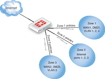
You can configure policies for connections to and from a zone, but not between interfaces in a zone. Using the above example, you can create a security policy to go between zone 1 and zone 3, but not between WAN2 and WAN1, or WAN1 and DMZ1.
This example explains how to set up a zone to include the Internal interface and a VLAN.
To create a zone - web-based manager
- Go to System > Network > Interface.
- Select the arrow on the Create New button and select Zone.
- Enter a zone name of
Zone_1. - Select the Internal interface and the virtual LAN interface vlan_accounting created previously.
- Select OK.
To create a zone - CLI
config system zone
edit Zone_1
set interface internal VLAN_1
end
Probing interfaces
Server probes can be used on interfaces. In order for this to occur, the probe response mode must first be configured, then the probe response must be allowed administrative access on the interface. The probe response mode can be:
none
|
Disable probe. |
http-probe
|
HTTP probe. |
twamp
|
Two way active measurement protocol. |
Both steps must be done through the CLI.
Configuring the probe
config system probe-response
set mode http-probe
end
Allowing the probe response to have administrative access to the interface
config system interface
edit <port>
set allowaccess probe-response
end
end
Copyright © 2018 Fortinet, Inc. All Rights Reserved. | Terms of Service | Privacy Policy
