Home > Online Help
Redundant route-based VPN configuration example
This example demonstrates a fully redundant site-to-site VPN configuration using route-based VPNs. At each site, the FortiGate unit has two interfaces connected to the Internet through different ISPs. This means that there are four possible paths for communication between the two units. In this example, these paths, listed in descending priority, are:
- FortiGate_1 WAN 1 to FortiGate_2 WAN 1
- FortiGate_1 WAN 1 to FortiGate_2 WAN 2
- FortiGate_1 WAN 2 to FortiGate_2 WAN 1
- FortiGate_1 WAN 2 to FortiGate_2 WAN 2
Example redundant route-based VPN configuration
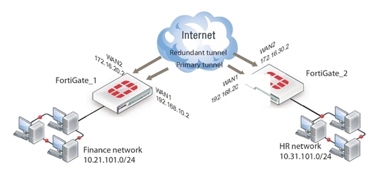
For each path, VPN configuration, security policies and routing are defined. By specifying a different routing distance for each path, the paths are prioritized. A VPN tunnel is established on each path, but only the highest priority one is used. If the highest priority path goes down, the traffic is automatically routed over the next highest priority path. You could use dynamic routing, but to keep this example simple, static routing is used.
Configuring FortiGate_1
When configuring FortiGate_1, you must:
- Configure the interfaces involved in the VPN.
- Define the Phase 1 configuration for each of the four possible paths, creating a virtual IPsec interface for each one.
- Define the Phase 2 configuration for each of the four possible paths.
- Configure routes for the four IPsec interfaces, assigning the appropriate priorities.
- Configure incoming and outgoing security policies between the internal interface and each of the virtual IPsec interfaces.
To configure the network interfaces
- Go to System > Network > Interfaces.
- Select the Internal interface and select Edit.
- Enter the following information and then select OK:
| Addressing mode |
Manual |
| IP/Netmask |
10.21.101.0/255.255.255.0
|
- Select the WAN1 interface and select Edit, enter the following information and then select OK:
| Addressing mode |
Manual |
| IP/Netmask |
192.168.10.2/255.255.255.0
|
- Select the WAN2 interface and select Edit, enter the following information and then select OK:
| Addressing mode |
Manual |
| IP/Netmask |
172.16.20.2/255.255.255.0
|
To configure the IPsec interfaces (Phase 1 configurations)
- Go to VPN > IPsec > Tunnels and create the new custom tunnel or edit an existing tunnel.
- Edit the Phase 1 Proposal (if it is not available, you may need to click the Convert to Custom Tunnel button).
- Enter the following information, and select OK:
| Name |
Site_1_A
|
| Remote Gateway |
Static IP Address |
| IP Address |
192.168.20.2
|
| Local Interface |
WAN1 |
| Mode |
Main |
| Authentication Method |
Preshared Key |
| Pre-shared Key |
Enter the preshared key. |
| Peer Options |
Any peer ID |
| Advanced |
|
| Dead Peer Detection |
Select |
- Create a new tunnel and enter the following Phase 1 information:
| Name |
Site_1_B
|
| Remote Gateway |
Static IP Address |
| IP Address |
172.16.30.2
|
| Local Interface |
WAN1 |
| Mode |
Main |
| Authentication Method |
Preshared Key |
| Pre-shared Key |
Enter the preshared key. |
| Peer Options |
Any peer ID |
| Advanced |
|
| Dead Peer Detection |
Select |
- Create a new tunnel and enter the following Phase 1 information:
| Name |
Site_1_C
|
| Remote Gateway |
Static IP Address |
| IP Address |
192.168.20.2
|
| Local Interface |
WAN2 |
| Mode |
Main |
| Authentication Method |
Preshared Key |
| Pre-shared Key |
Enter the preshared key. |
| Peer Options |
Any peer ID |
| Advanced |
|
| Dead Peer Detection |
Select |
- Create a new tunnel and enter the following Phase 1 information:
| Name |
Site_1_D
|
| Remote Gateway |
Static IP Address |
| IP Address |
172.16.30.2
|
| Local Interface |
WAN2 |
| Mode |
Main |
| Authentication Method |
Preshared Key |
| Pre-shared Key |
Enter the preshared key. |
| Peer Options |
Any peer ID |
| Advanced |
|
| Dead Peer Detection |
Select |
To define the Phase 2 configurations for the four VPNs
- Open the Phase 2 Selectors panel.
- Enter the following information and select OK:
| Name |
Route_A
|
| Phase 1 |
Site_1_A |
- Enter the following Phase 2 information for the subsequent route:
| Name |
Route_B
|
| Phase 1 |
Site_1_B |
- Enter the following Phase 2 information for the subsequent route:
| Name |
Route_C
|
| Phase 1 |
Site_1_C |
- Enter the following Phase 2 information for the subsequent route:
| Name |
Route_D
|
| Phase 1 |
Site_1_D |
To configure routes
- Go to Router > Static > Static Routes.
For low-end FortiGate units, go to System > Network > Routing.
- Select Create New, enter the following default gateway information and then select OK:
| Destination IP/Mask |
0.0.0.0/0.0.0.0
|
| Device |
WAN1 |
| Gateway |
192.168.10.1
|
| Distance (Advanced) |
10
|
- Select Create New, enter the following information and then select OK:
| Destination IP/Mask |
10.31.101.0/255.255.255.0
|
| Device |
Site_1_A |
| Distance (Advanced) |
1
|
- Select Create New, enter the following information and then select OK:
| Destination IP/Mask |
10.31.101.0/255.255.255.0
|
| Device |
Site_1_B |
| Distance (Advanced) |
2
|
- Select Create New, enter the following information and then select OK:
| Destination IP/Mask |
10.31.101.0/255.255.255.0
|
| Device |
Site_1_C |
| Distance (Advanced) |
3
|
- Select Create New, enter the following information and then select OK:
| Destination IP/Mask |
10.31.101.0/255.255.255.0
|
| Device |
Site_1_D |
| Distance (Advanced) |
4
|
To configure security policies
- Go to Policy & Objects > Policy > IPv4 and select Create New.
- Enter the following information, and then select OK:
| Incoming Interface |
Internal |
| Source Address |
All |
| Outgoing Interface |
Site_1_A |
| Destination Address |
All |
| Schedule |
Always |
| Service |
Any |
| Action |
ACCEPT |
- Select Create New.
- Enter the following information, and select OK:
| Incoming Interface |
Site_1_A |
| Source Address |
All |
| Outgoing Interface |
Internal |
| Destination Address |
All |
| Schedule |
Always |
| Service |
Any |
| Action |
ACCEPT |
- Select Create New.
- Enter the following information, and select OK:
| Incoming Interface |
Internal |
| Source Address |
All |
| Outgoing Interface |
Site_1_B |
| Destination Address |
All |
| Schedule |
Always |
| Service |
Any |
| Action |
ACCEPT |
- Select Create New.
- Enter the following information, and select OK:
| Incoming Interface |
Site_1_B |
| Source Address |
All |
| Outgoing Interface |
Internal |
| Destination Address |
All |
| Schedule |
Always |
| Service |
Any |
| Action |
ACCEPT |
- Select Create New.
- Enter the following information, and select OK:
| Incoming Interface |
Internal |
| Source Address |
All |
| Outgoing Interface |
Site_1_C |
| Destination Address |
All |
| Schedule |
Always |
| Service |
Any |
| Action |
ACCEPT |
- Select Create New.
- Enter the following information, and select OK:
| Incoming Interface |
Site_1_C |
| Source Address |
All |
| Outgoing Interface |
Internal |
| Destination Address |
All |
| Schedule |
Always |
| Service |
Any |
| Action |
ACCEPT |
- Select Create New.
- Enter the following information, and select OK:
| Incoming Interface |
Internal |
| Source Address |
All |
| Outgoing Interface |
Site_1_D |
| Destination Address |
All |
| Schedule |
Always |
| Service |
Any |
| Action |
ACCEPT |
- Select Create New.
- Enter the following information, and select OK:
| Incoming Interface |
Site_1_D |
| Source Address |
All |
| Outgoing Interface |
Internal |
| Destination Address |
All |
| Schedule |
Always |
| Service |
Any |
| Action |
ACCEPT |
Configuring FortiGate_2
The configuration for FortiGate_2 is very similar to that of FortiGate_1. You must:
- Configure the interfaces involved in the VPN.
- Define the Phase 1 configuration for each of the four possible paths, creating a virtual IPsec interface for each one.
- Define the Phase 2 configuration for each of the four possible paths.
- Configure routes for the four IPsec interfaces, assigning the appropriate priorities.
- Configure incoming and outgoing security policies between the internal interface and each of the virtual IPsec interfaces.
To configure the network interfaces
- Go to System > Network > Interfaces.
- Select the Internal interface and then select Edit. Enter the following information and then select OK:
| Addressing mode |
Manual |
| IP/Netmask |
10.31.101.0/255.255.255.0
|
- Select the WAN1 interface and then select Edit. Enter the following information and then select OK:
| Addressing mode |
Manual |
| IP/Netmask |
192.168.20.2/255.255.255.0
|
- Select the WAN2 interface and then select Edit. Enter the following information and then select OK:
| Addressing mode |
Manual |
| IP/Netmask |
172.16.30.2/255.255.255.0
|
To configure the IPsec interfaces (Phase 1 configurations)
- Go to VPN > IPsec > Tunnels and create the new custom tunnel or edit an existing tunnel.
- Edit the Phase 1 Proposal (if it is not available, you may need to click the Convert to Custom Tunnel button).
- Enter the following information, and select OK:
| Name |
Site_2_A
|
| Remote Gateway |
Static IP Address |
| IP Address |
192.168.10.2
|
| Local Interface |
WAN1 |
| Mode |
Main |
| Authentication Method |
Preshared Key |
| Pre-shared Key |
Enter the preshared key. |
| Peer Options |
Any peer ID |
| Advanced |
|
| Dead Peer Detection |
Select |
- Create a new tunnel and enter the following Phase 1 information:
| Name |
Site_2_B
|
| Remote Gateway |
Static IP Address |
| IP Address |
172.16.20.2
|
| Local Interface |
WAN1 |
| Mode |
Main |
| Authentication Method |
Preshared Key |
| Pre-shared Key |
Enter the preshared key. |
| Peer Options |
Any peer ID |
| Advanced |
|
| Dead Peer Detection |
Select |
- Create a new tunnel and enter the following Phase 1 information:
| Name |
Site_2_C
|
| Remote Gateway |
Static IP Address |
| IP Address |
192.168.10.2
|
| Local Interface |
WAN1 |
| Mode |
Main |
| Authentication Method |
Preshared Key |
| Pre-shared Key |
Enter the preshared key. |
| Peer Options |
Any peer ID |
| Advanced |
|
| Dead Peer Detection |
Select |
- Create a new tunnel and enter the following Phase 1 information:
| Name |
Site_2_D
|
| Remote Gateway |
Static IP Address |
| IP Address |
172.16.20.2
|
| Local Interface |
WAN1 |
| Mode |
Main |
| Authentication Method |
Preshared Key |
| Pre-shared Key |
Enter the preshared key. |
| Peer Options |
Any peer ID |
| Advanced |
|
| Dead Peer Detection |
Select |
To define the Phase 2 configurations for the four VPNs
- On the first VPN route, open the Phase 2 Selectors panel.
- Enter the following information and select OK:
| Name |
Route_A
|
| Phase 1 |
Site_2_A
|
- Enter the following Phase 2 information for the subsequent route:
| Name |
Route_B
|
| Phase 1 |
Site_2_B
|
- Enter the following Phase 2 information for the subsequent route:
| Name |
Route_C
|
| Phase 1 |
Site_2_C
|
- Enter the following Phase 2 information for the subsequent route:
| Name |
Route_D
|
| Phase 1 |
Site_2_D
|
To configure routes
- Go to Router > Static > Static Routes.
For low-end FortiGate units, go to System > Network > Routing.
- Select Create New, enter the following default gateway information and then select OK:
| Destination IP/Mask |
0.0.0.0/0.0.0.0
|
| Device |
WAN1 |
| Gateway |
192.168.10.1
|
| Distance (Advanced) |
10
|
- Select Create New, enter the following information and then select OK:
| Destination IP/Mask |
10.21.101.0/255.255.255.0
|
| Device |
Site_2_A |
| Distance (Advanced) |
1
|
- Select Create New, enter the following information and then select OK:
| Destination IP/Mask |
10.21.101.0/255.255.255.0
|
| Device |
Site_2_B |
| Distance (Advanced) |
2
|
- Select Create New, enter the following information and then select OK:
| Destination IP/Mask |
10.21.101.0/255.255.255.0
|
| Device |
Site_2_C |
| Distance (Advanced) |
3
|
- Select Create New, enter the following information and then select OK:
| Destination IP/Mask |
10.21.101.0/255.255.255.0
|
| Device |
Site_2_D |
| Distance (Advanced) |
4
|
To configure security policies
- Go to Policy & Objects > Policy > IPv4 and select Create New.
- Enter the following information, and select OK:
| Incoming Interface |
Internal |
| Source Address |
All |
| Outgoing Interface |
Site_2_A |
| Destination Address |
All |
| Schedule |
Always |
| Service |
Any |
| Action |
ACCEPT |
- Select Create New.
- Enter the following information, and select OK:
| Incoming Interface |
Site_2_A |
| Source Address |
All |
| Outgoing Interface |
Internal |
| Destination Address |
All |
| Schedule |
Always |
| Service |
Any |
| Action |
ACCEPT |
- Select Create New.
- Enter the following information, and select OK:
| Incoming Interface |
Internal |
| Source Address |
All |
| Outgoing Interface |
Site_2_B |
| Destination Address |
All |
| Schedule |
Always |
| Service |
Any |
| Action |
ACCEPT |
- Select Create New.
- Enter the following information, and select OK:
| Incoming Interface |
Site_2_B |
| Source Address |
All |
| Outgoing Interface |
Internal |
| Destination Address |
All |
| Schedule |
Always |
| Service |
Any |
| Action |
ACCEPT |
- Select Create New.
- Enter the following information, and select OK:
| Incoming Interface |
Internal |
| Source Address |
All |
| Outgoing Interface |
Site_2_C |
| Destination Address |
All |
| Schedule |
Always |
| Service |
Any |
| Action |
ACCEPT |
- Select Create New.
- Enter the following information, and select OK:
| Incoming Interface |
Site_2_C |
| Source Address |
All |
| Outgoing Interface |
Internal |
| Destination Address |
All |
| Schedule |
Always |
| Service |
Any |
| Action |
ACCEPT |
- Select Create New.
- Enter the following information, and select OK:
| Incoming Interface |
Internal |
| Source Address |
All |
| Outgoing Interface |
Site_2_D |
| Destination Address |
All |
| Schedule |
Always |
| Service |
Any |
| Action |
ACCEPT |
- Select Create New.
- Enter the following information, and select OK:
| Incoming Interface |
Site_2_D |
| Source Address |
All |
| Outgoing Interface |
Internal |
| Destination Address |
All |
| Schedule |
Always |
| Service |
Any |
| Action |
ACCEPT |

