
Scenarios
This chapter contains practical examples of how to use the FortiSwitch unit to manage a network. The scenarios are as follows:
- Scenario 1: Allowing access to specific users on the marketing VLAN
- Scenario 2: Adding a specific device to the marketing VLAN
- Scenario 3: Accessing the marketing VLAN remotely using an SSL VPN
- Scenario 4: Configuring the accounting VLAN using an SFP port
- Scenario 5: Connecting a VoIP phone to the FortiSwitch
- Scenario 6: Connecting a FortiAP unit to the FortiSwitch
The Example Network
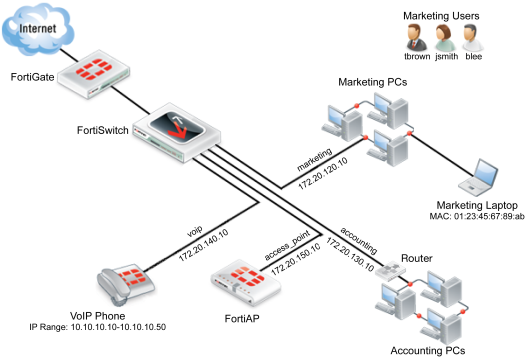
All the scenarios are interrelated and are used to manage an example network with the following attributes:
- The FortiSwitch unit used is a FortiSwitch-224D-POE, serial number FS224D3W14000370.
- The FortiSwitch unit’s port 24 connects to port1 on the FortiGate unit.
- The LAN is divided into four distinct VLANs, configured as follows:
| VLAN | IP | Device(s) | Port(s) | Policy ID(s) | GUI Color |
|---|---|---|---|---|---|
| marketing | 172.20.120.10/255.255.255.0 | marketing PCs, marketing laptop | 3-6 | 2, 3 |

|
| accounting | 172.20.130.10/255.255.255.0 | accounting PCs | 21 | 4 |

|
| voip | 172.20.140.10/255.255.255.0 | VoIP phone | 10 | 5 |

|
| access_point | 172.20.150.10/255.255.255.0 | FortiAP | 1 | 6 |

|
- There are six devices that connect directly to the FortiSwitch unit’s ports using Ethernet cables: the 3 marketing PCs, the marketing laptop, the VoIP phone, and the FortiAP unit.
- The accounting VLAN connects to the FortiSwitch using an SFP port.
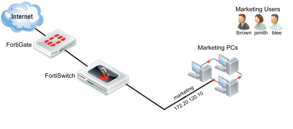
- There are three marketing employees (Jane Smith, Tom Brown, Bob Lee) who will use the marketing VLAN using the marketing PCs.
- The MAC address of the marketing laptop is 01:23:45:67:89:ab.
- The IP range for the VoIP phone is 10.10.10.10-10.10.10.50.
- The FortiAP unit is a FortiAP-11C, serial number FAP11C3X12000412.

Scenario 1: Allowing access to specific users on the marketing VLAN
In Scenario 1, the policies for the marketing VLAN will be created so that different users have different access. The firewall policy will be created so that all three marketing employees (Jane Smith, Tom Brown, Bob Lee) have user accounts. These accounts will be put into one of two groups: full-time and part-time. Full-time employees will always have network access, while part-time employees will only have access on Mondays, Wednesdays and Fridays. This policy will apply to each user when they use any of the PCs that connect to the marketing VLAN through ports 3, 4, 5 or 6 on the FortiSwitch.
Creating a policy to match scenario 1 requires:
- Creating users.
- Creating groups.
- Creating a schedule.
- Configuring the firewall policies.
Using the web-based manager
Creating a User Group
- Go to User & Device > User > User Groups and select Create New.
- Name the user group part-time.
- Set Type as Firewall.
- Select OK.
The entry part-time will now appear on the user group list. Repeat these steps to create another user group, named full-time.
Creating a User
- Go to User & Device > User > User Definition. Select Create New.
- Use the User Creation Wizard to create a user. In part 1, select Local User.
- In part 2, change the following settings:
| User Name | blee |
| Password | password |
- In part 3, enter the email address blee@example.com
- In part 4, select Enable and User Group. Set part-time as the group.
- Select Done.
The entry blee will now appear in the user list. Repeat these steps to create user accounts tbrown and jsmith and add both of these accounts to the full-time group.
Creating a Schedule
- Go to Policy & Objects > Objects > Schedules. Select Create New and then select Recurring.
- Change the following settings:
| Name | part-time_schedule |
| Day of the Week | Monday, Wednesday, Friday |
- Select OK.
The entry part-time schedule will now appear on the schedules list.
Configuring the Firewall Policy
- Go to Policy & Objects > Policy > IPv4 and select Create New.
- Set the policy to use the following the following settings, allowing access for part-time employees:
| Incoming Interface | marketing |
| Source Address | all |
| Source User(s) | part-time |
| Outgoing Interface | wan1 |
| Destination Address | all |
| Schedule | part-time_schedule |
| Service | ALL |
| Action | ACCEPT |
| Enable NAT | Enable |
| Logging Options | Log all Sessions |
- Select OK.
- Go to Policy & Objects > Policy> IPv4 and create a new policy.
- Change the following settings to set access for full-time employees:
| Incoming Interface | marketing |
| Source Address | all |
| Source User(s) | full-time |
| Outgoing Interface | wan1 |
| Destination Address | all |
| Schedule | always |
| Service | ALL |
| Action | ACCEPT |
| Enable NAT | Enable |
| Logging Options | Log all Sessions |
- Select OK.
You have now finished creating the policies that match scenario 1. These policies will apply to all three users when they use any of the PCs that connect to the marketing VLAN.
Using the CLI
- Create the 3 users.
config user local
edit blee
set type password
set passwd password
next
edit tbrown
set type password
set passwd password
next
edit jsmith
set type password
set passwd password
end
- Create the 2 user groups and add the users to them.
config user group
edit part-time
set group-type firewall
set member blee
next
edit full-time
set group-type firewall
set member tbrown jsmith
end
- Create the schedule for part-time employees.
config firewall schedule recurring
edit part-time_schedule
set day monday wednesday friday
end
- Create two firewall policies for the marketing VLAN, one for each user group:
config firewall policy
edit 2
set srcintf marketing
set dstintf wan1
set srcaddr all
set dstaddr all
set nat enable
set action accept
set schedule part-time_schedule
set logtraffic all
set groups part-time
set service ALL
next
edit 3
set srcintf marketing
set dstintf wan1
set srcaddr all
set dstaddr all
set nat enable
set action accept
set schedule always
set logtraffic all
set groups full-time
set service ALL
end
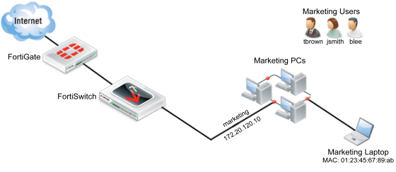
Scenario 2: Adding a specific device to the marketing VLAN
In Scenario 2, a new policy will be created for the marketing VLAN that will be used by the marketing laptop. This policy will affect the marketing laptop that is used periodically for tasks such as boardroom presentations or for guests, tasks for which the laptop requires Internet access. The laptop will access the Internet by connecting to the marketing VLAN through ports 3, 4, 5 or 6 on the FortiSwitch. Adding a new policy for the laptop will allow it to connect without requiring user authentication and will also limit the scope of the device’s access.
Creating a policy to match scenario 2 requires:
- Assigning a reserve IP to the laptop.
- Creating a firewall address for the reserve IP.
- Creating a firewall policy that uses the reserve IP.
Using the web-based manager
Assigning a Reserve IP to the Laptop
- Go to System > Network > Interfaces and select marketing.
- Under DHCP Server, expand the Advanced options.
- In the MAC Address Access Control List and select Create New.
- Change the following settings:
| MAC | 01:23:45:67:89:ab |
| IP | 172.20.120.254 |
| Action | Reserve IP |
Creating a Firewall Address for the Reserve IP
- Go to Policy & Objects > Objects > Addresses and select Create New.
- Change the following settings:
| Category | Address |
| Name | marketing_laptop |
| Type | Subnet |
| Subnet/IP Range | 172.20.120.254 |
| Interface | marketing |
Configuring a Firewall Policy
- Go to Policy & Objects > Policy > IPv4 and select Create New.
- Change the following settings:
| Incoming Interface | marketing |
| Source Address | marketing_laptop |
| Outgoing Interface | wan1 |
| Destination Address | all |
| Schedule | always |
| Service | HTTP HTTPS DNS |
| Action | ACCEPT |
| Enable NAT | Enabled |
| Logging Options | Log all Sessions |
- Select OK.
- In the policy list, select the column on the far left for the new policy (usually Seq #) and drag the policy above the previous policy for the marketing VLAN. This will ensure that the laptop will be identified through this policy.
You have now finished creating a policy that matches scenario 2. This policy will apply to anyone who uses the laptop to connect to the marketing VLAN using an Ethernet cable.
Using the CLI
- Assign a reserve IP to the laptop.
config system dhcp server
edit 2
config reserved-address
edit 1
set action reserved
set ip 172.20.120.254
set mac 01:23:45:67:89:ab
end
end
- Create a firewall address for the reserve IP.
config firewall address
edit marketing_laptop
set subnet 172.20.120.254
end
- Create a firewall policy for the marketing VLAN that uses the reserve IP.
config firewall policy
edit 4
set srcintf marketing
set dstintf wan1
set srcaddr marketing_laptop
set dstaddr all
set action accept
set schedule always
set service HTTP HTTPS DNS
set logtraffic all
set nat enable
end
- Place the new firewall policy at the top of the policy list.
config firewall policy
move 4 before 2
end
Scenario 3: Accessing the marketing VLAN remotely using an SSL VPN
In Scenario 3, a policy is created to allow remote access to the marketing VLAN, using a virtual private network (VPN) tunnel. This policy will allow marketing employee Tom Brown to connect to the marketing VLAN remotely from his home. The default IP Pool, SSLVPN_TUNNEL_ADDR1, will be used to configure the SSL VPN web portal. The computer Tom Brown is using to access the network remotely has a dynamic IP address and will be using the FortiClient application to auto connect to the VPN tunnel. To maintain security, split tunneling will be disabled. This policy will be used whenever Tom Brown accesses the marketing VLAN remotely.
Creating a policy to match scenario 3 requires:
- Creating a user group.
- Creating a firewall address for the marketing VLAN.
- Creating an SSL VPN portal.
- Creating a SSL VPN firewall policy for the marketing VLAN.
Using the web-based manager
Creating a User Group
- Go to User & Device > User > User Groups and select Create New.
- Name the Group remote access.
- Set Type as Firewall.
- Highlight tbrown on the Available Users list.
- Select the right-pointing arrow to move tbrown to the Members list.
- Select OK.
The entry remote access will now appear on the Group list, with tbrown listed under Members.
Creating a Firewall Address for the marketing VLAN
- Go to Policy & Objects > Objects > Addresses and select Create New. Change the following settings:
| Address Name | marketing VLAN |
| Type | Subnet |
| Subnet/IP Range | 172.20.120.14/255.255.255.0 |
| Interface | marketing |
- Select OK.
Creating an SSL VPN Portal
- Go to VPN > SSL > Portals and select Create New. Change the following settings:
| Name | marketing-remote |
| Enable Tunnel Mode | Enable |
| Enable Split Tunneling | Disable |
| IP Pools | SSLVPN_TUNNEL_ADDR1 |
| Enable Web Mode | Enable |
- Select Apply.
Creating a Firewall Policy
- Go to Policy & Objects > Policy > IPv4 and select Create New.
- Change the following settings to allow Tom Brown to access the marketing VLAN:
| Incoming Interface | ssl.root (sslvpn tunnel interface) |
| Source Address | marketing_laptop |
| Outgoing Interface | marketing |
| Destination Address | all |
| Schedule | always |
| Service | ALL |
| Action | ACCEPT |
| Enable NAT | Enabled |
| Logging Options | Log all Sessions |
- Select OK.
- Go to Policy & Objects > Policy > IPv4 and create a second policy.
- Change the following settings to allow Tom Brown to access the Internet through the FortiGate:
| Incoming Interface | ssl.root (sslvpn tunnel interface) |
| Source Address | marketing_laptop |
| Outgoing Interface | wan1 |
| Destination Address | all |
| Schedule | always |
| Service | HTTP HTTPS DNS |
| Action | ACCEPT |
| Enable NAT | Enabled |
| Logging Options | Log all Sessions |
- Select OK.
|
|
The FortiClient SSL VPN tunnel client will also need to be configured, in order for the Tom Brown to connect to the SSL VPN tunnel. |
You have now finished creating a policy that matches scenario 4. This policy will be used whenever Tom Brown accesses the marketing VLAN remotely.
Using the CLI
- Create the user group for remote users.
config user group
edit remote-access
set group-type firewall
set member tbrown
end
- Create a firewall address for the marketing VLAN.
config firewall address
edit marketing_VLAN
set associated-interface marketing
set subnet 172.20.120.14 255.255.255.0
end
- Create the SSL VPN web portal.
config vpn ssl web portal
edit marketing-remote
set allow-access web ftp ssh
config widget
edit 1
set type tunnel
set split-tunneling disable
set ip-pools SSLVPN_TUNNEL_ADDR1
set auto-connect enable
end
end
- Create a firewall policy to allow remote access to the marketing VLAN.
config firewall policy
edit 3
set srcintf wan1
set dstintf marketing
set dstaddr marketing_VLAN
set action ssl-vpn
set schedule always
set groups remote_access
set users tbrown
set sslvpn-portal marketing-remote
end
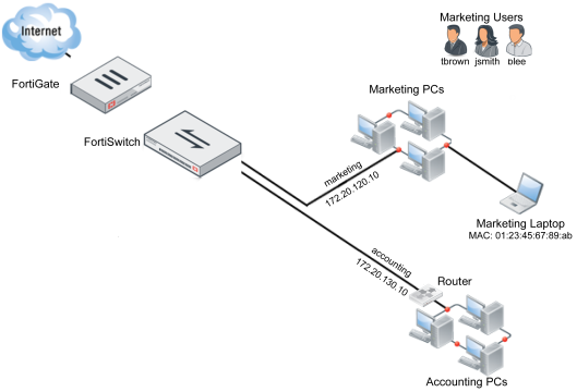
Scenario 4: Configuring the accounting VLAN using an SFP port
|
|
The SFP ports should only be used to connect UL-listed optical transceiver products, rated Laser Class 1.33V DC. |
In Scenario 4, a second VLAN will be created on the FortiSwitch, to be used for the accounting department. This VLAN will connect to the FortiSwitch unit using a copper SFP receiver that has been installed in the FortiSwitch. Due to the sensitive nature of information within the accounting network, the firewall policy that controls traffic to this network uses the default profile for all security features.
Creating an interface to match scenario 4 requires:
- Creating and assigning a VLAN.
- Configuring a firewall policy.
|
|
SFP ports are only available on certain FortiSwitch models. SFP ports are also shared with Ethernet ports and so when an SFP port is used, the Ethernet port with the same number cannot be. |
Using the web-based manager
Creating and Assigning the VLAN
- Go to WiFi & Switch Controller > Switch Network > Virtual Switch and select Create New. Change the following settings:
| Name | accounting |
| Color |

|
| IP/Network Mask | 172.20.130.15/255.255.255.0 |
- Select OK.
- Go to WiFi & Switch Controller > Managed Devices > Managed FortiSwitch and assign FortiSwitch port 21 to accounting.
Configuring the Firewall Policy
- Go to Policy & Objects > Policy > IPv4 and select Create New. Change the following settings:
| Incoming Interface | accounting |
| Source Address | all |
| Outgoing Interface | wan1 |
| Destination Address | all |
| Schedule | always |
| Service | ALL |
| Action | ACCEPT |
| Enable NAT | Enabled |
| Logging Options | Log all Sessions |
- Enable the following Security Profiles and set them to use the default profile: AntiVirus, Web Filter, Application Control, IPS, Email Filter, DLP Sensor, and SSL/SSH Inspection.
- Select OK.
You have now finished creating a policy that matches scenario 5. This policy will be used for all traffic on the accounting VLAN.
Using the CLI
- Create the accounting VLAN.
config switch-controller vlan
edit accounting
set color 32
end
- Set the VLAN’s IP address.
config system interface
edit marketing
set ip 172.20.130.15 255.255.255.0
end
- Assign the accounting VLAN to port 21.
config switch-controller managed-switch
edit FS224D3W14000370
config ports
edit port21
set vlan accounting
end
end
- Create a firewall policy for the accounting VLAN that uses the default security profiles.
config firewall policy
edit 4
set srcintf accounting
set dstintf wan1
set srcaddr all
set dstaddr all
set action accept
set schedule always
set service ALL
set logtraffic all
set nat enable
set av-profile default
set webfilter-profile default
set spamfilter-profile default
set dlp-sensor default
set ips-sensor default
set application-list default
set profile-protocol-options default
set deep-inspection-options default
end
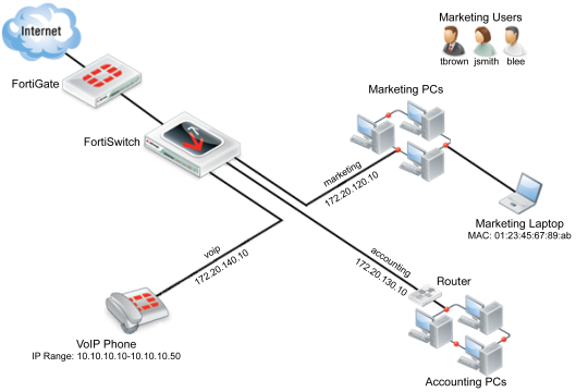
Scenario 5: Connecting a VoIP phone to the FortiSwitch
In Scenario 5, an interface will be configured to use a Voice over IP (VoIP) phone. This VoIP phone will be assigned the IP range 10.10.10.10-10.10.10.50 and connect to the FortiSwitch unit through port 10 using an Ethernet cable. The FortiGate unit’s default VoIP profile will be used.
Creating an interface to match scenario 5 requires:
- Creating and assigning a VLAN.
- Creating a firewall address for the VoIP phone.
- Configuring a firewall policy.
Using the web-based manager
Creating and Assigning the VLAN
- Go to WiFi & Switch Controller > Switch Network > Virtual Switch and select Create New. Change the following settings:
| Name | voip |
| Color |

|
| IP/Network Mask | 172.20.140.16/255.255.255.0 |
- Select OK.
- Go to WiFi & Switch Controller > Managed Devices > Managed FortiSwitch and assign FortiSwitch port10 to voip.
Creating a Firewall Address
- Go to Policy & Objects > Objects > Addresses and select Create New. Change the following settings:
| Category | Address |
| Name | voip |
| Color |

|
| Type | IP Range |
| Subnet/IP Range | 10.10.10.10-10.10.10.50 |
| Interface | voip |
- Select OK.
Create a Firewall Policy
- Go to Policy & Objects > Policy > IPv4 and select Create New. Change the following settings:
| Incoming Interface | voip |
| Source Address | voip_phone |
| Outgoing Interface | wan1 |
| Destination Address | all |
| Schedule | always |
| Service | SIP |
| Action | ACCEPT |
| Enable NAT | Enabled |
| Logging Options | Log all Sessions |
- Go to Policy & Objects > Policy > IPv4 and select Create New. Change the following settings:
- Enable the VoIP Security Profile and set it to default.
You have now finished creating a policy that matches scenario 6.
Using the CLI
- Create the voip VLAN.
config switch-controller vlan
edit voip
set color 25
end
- Set the VLAN’s IP address.
config system interface
edit marketing
set ip 172.20.140.16 255.255.255.0
end
- Assign the voip VLAN to port 10.
config switch-controller managed-switch
edit FS224D3W14000370
config ports
edit port10
set vlan voip
end
end
- Configure the firewall policy.
config firewall policy
edit 5
set srcintf voip
set dstintf wan1
set srcaddr voip_phone
set dstaddr all
set action accept
set schedule always
set service SIP
set logtraffic all
set nat enable
set voip-profile default
end
Scenario 6: Connecting a FortiAP unit to the FortiSwitch
In Scenario 6, an interface will be configured to use a FortiAP unit that will provide wireless Internet access.
Creating an interface to match scenario 6 requires:
- Creating and assigning a VLAN.
- Authorizing the FortiAP unit.
- Creating an SSID.
- Creating a firewall address.
- Configuring a firewall policy.
The WiFi network provided by the access point will use the marketing schedule and allow HTTP and HTTPS traffic.
Using the web-based manager
Creating and Assigning the VLAN
- Go to WiFi & Switch Controller > Switch Network > Virtual Switch and select Create New. Change the following settings:
| Name | access_point |
| Color |

|
| IP/Network Mask | 172.20.150.17/255.255.255.0 |
| DHCP Server | Enable |
- Select OK.
- Go to WiFi & Switch Controller > Managed Devices > Managed FortiSwitch and assign FortiSwitch port1 to access_point.
Authorizing the FortiAP unit
- Go to WiFi & Switch Controller > Managed Devices > Managed FortiAPs.
- Right-click on the FortiAP unit and select Authorize.
A icon with a checkmark now appears in the Status column.
Creating an SSID
- Go to WiFi & Switch Controller > WiFi Network > SSIDs and select Create New.
- Change the following settings:
| Name | WLAN |
| Type | WiFi SSID |
| Traffic Mode | Tunnel to Wireless Controller |
| IP/Network Mask | 172.20.150.17/255.255.255.0 |
| DHCP Server | Enabled |
| SSID | wireless |
| Pre-shared Key | password |
- Select OK.
Create a Firewall Policy
- Go to Policy & Objects > Policy > IPv4 and select Create New.
- Change the following settings:
| Incoming Interface | access_point |
| Outgoing Interface | wan1 |
| Destination Address | all |
| Schedule | always |
| Service | HTTP HTTPS DNS |
| Action | ACCEPT |
| Enable NAT | Enabled |
| Logging Options | Log all Sessions |
- Select OK.
- Go to WiFi & Switch Controller > Managed Devices > Managed FortiAPs. The Status icon now appears in green, showing that the FortiSwitch unit is online.
You have now finished creating a policy that matches scenario 7.
Using the CLI
- Create the access_point VLAN.
config switch-controller vlan
edit access_point
set color 7
end
- Assign the access_point VLAN to port 1.
config switch-controller managed-switch
edit FS224D3W14000370
config ports
edit port1
set vlan access_point
end
end
- Set the interface IP and enable CAPWAP.
config system interface
edit access_point
set ip 172.20.150.17
set allowaccess capwap
end
- Enable the FortiAP unit.
config wireless-controller wtp
edit FAP11C3X13000412
set admin enable
end
- Create an SSID for the FortiAP unit.
config wireless-controller vap
edit WLAN
set ssid wireless
set passphrase password
end
- Configure the firewall policy.
config firewall policy
edit 6
set srcintf access_point
set dstintf wan1
set srcaddr all
set dstaddr all
set action accept
set schedule always
set service HTTP HTTPS DNS
set logtraffic all
set nat enable
end
Copyright © 2018 Fortinet, Inc. All Rights Reserved. | Terms of Service | Privacy Policy
