
Dual-homed BGP example
This is an example of a small network that uses BGP routing connections to two ISPs. This is a common configuration for companies that need redundant connections to the Internet for their business.
This configuration is for a small company connected to two ISPs. The company has one main office, the Head Office, and uses static routing for internal routing on that network.
Both ISPs use BGP routing, and connect to the Internet directly. They want the company to connect to the ISP networks using BGP. They also use graceful restart to prevent unneeded updates, and use smaller timer values to detect network failures faster.
As can be expected, the company wants to keep their BGP configuration relatively simple and easy to manage. The current configuration has only 3 routers to worry about — the 2 ISP border routers, and the FortiGate unit. This means the FortiGate unit will only have two neighbor routers to configure.
This configuration has the added benefit of being easy to expand if the Company wants to add a remote office in the future.
To keep the configuration simple, the Company is allowing only HTTP, HTTPS, FTP, and DNS traffic out of the local network. This will allow employees access to the Internet and their web-mail.
This section includes the following topics:
- Network layout and assumptions
- Configuring the FortiGate unit
- Configuring other networking devices
- Testing this configuration
Why dual home?
Dual homing means having two separate independent connections to the Internet. Servers in this configuration have also been called bastion hosts and can include DNS servers which require multiple connections.
Benefits of dual homing can include:
- Redundant Internet connection that essentially never fails
- Faster connections through one ISP or the other for some destinations, such as other clients of those ISPs
- Load balancing traffic to your Company network
- Easier to enable more traffic through two connections than upgrading one connection to bigger bandwidth
- Easier to create protection policies for different traffic through a specific ISP
Some companies require reliable Internet access at all times as part of their business. Consider a doctor operating remotely who has their Internet connection fail — the consequences could easily be life or death.
Dual homing is extra expense for the second ISP connection, and more work to configure and maintain the more complex network topology.
Potential dual homing issues
BGP comes with load balancing issues, and dual homing is the same category. BGP does not inherently deal well with load balancing, or getting default routes through BGP. Ideally one connect may be best for certain destinations, but it may not have that traffic routed to it making the load balancing less than perfect. This kind of fine tuning can be very time consuming, and usually results in a best effort situation.
When dual homing is not configured properly, your network may become a link between your ISPs and result in very high traffic between the ISPs that does not originate from your network. The problems with this situation are that your traffic may not have the bandwidth it needs, and you will be paying for a large volume of traffic that is not yours. This problem can be solved by not broadcasting or redistributing BGP routes between the ISPs.
If you learn your default routes from the ISPs in this example, you may run into an asymmetric routing problem where your traffic loops out one ISP and back to you through the other ISP. If you think this may be happening you can turn on asymmetric routing on the FortiGate unit (config system settings, set asymmetric enable) to verify that really is the problem. Turn this feature off once this is established since it disables many features on the FortiGate by disabling stateful inspection. Solutions for this problem can include using static routes for default routes instead of learning them through BGP, or configuring VDOMs on your FortiGate unit to provide a slightly different path back that is not a true loop.
Network layout and assumptions
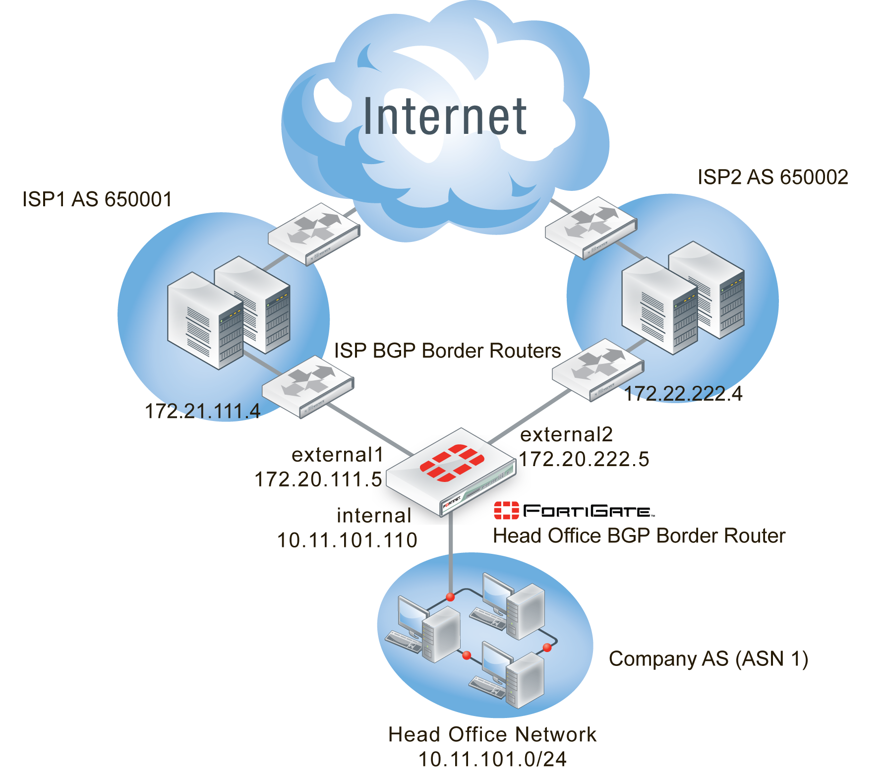
The network layout for the basic BGP example involves the company network being connected to both ISPs as shown below. In this configuration the FortiGate unit is the BGP border router between the Company AS, ISP1’s AS, and ISP2’s AS.
The components of the layout include:
- The Company AS (AS number 1) is connected to ISP1 and ISP2 through the FortiGate unit.
- The Company has one internal network — the Head Office network at 10.11.101.0/24.
- The FortiGate unit internal interface is on the the Company internal network with an IP address of 10.11.101.110.
- The FortiGate unit external1 interface is connected to ISP1’s network with an IP address of 172.20.111.5, an address supplied by the ISP.
- The FortiGate unit external2 interface is connected to IPS2’s network with an IP address of 172.20.222.5, an address supplied by the ISP.
- ISP1 AS has an AS number of 650001, and ISP2 has an AS number of 650002.
- Both ISPs are connected to the Internet.
- The ISP1 border router is a neighbor (peer) of the FortiGate unit. It has an address of 172.21.111.4.
- The ISP2 border router is a neighbor (peer) of the FortiGate unit. It has an address of 172.22.222.4.
- Apart from graceful restart, and shorter timers (holdtimer, and keepalive) default settings are to be used whenever possible.
Basic BGP network topology
Assumptions
The basic BGP configuration procedure follows these assumptions:
- ISP1 is the preferred route, and ISP2 is the secondary route
- All basic configuration can be completed in both GUI and CLI
- Only one AS is used for the Company
For these reasons this example configuration does not include:
- Bi-directional forwarding detection (BFD)
- Route maps
- Access lists
- Changing redistribution defaults — make link when example is set up
- IPv6
For more information on these features, see the corresponding section.
Configuring the FortiGate unit
In this topology, the FortiGate unit is the link between the Company Network and the ISP network. The FortiGate unit is the only BGP router on the Company Network, but there is at least one other BGP router on the ISP Network — there may be more but we don’t have that information.
As mentioned in the general configuration steps, the ISP must be notified of the Company’s BGP router configuration when complete as it will need to add the FortiGate BGP router as a neighbor router on its domain. This step is required for the FortiGate unit to receive BGP routing updates from the ISP network and outside networks.
If the ISP has any special BGP features enabled such as graceful restart, or route dampening that should be determined up front so those features can be enabled on the FortiGate unit.
To configure the FortiGate unit as a BGP router
- Configure interfaces and default routes
- Configure firewall services, addresses, and policies
- Set the FortiGate BGP information
- Add the internal network to the AS
- Additional FortiGate BGP configuration
Configure interfaces and default routes
The FortiGate unit is connected to three networks — Company Network on the internal interface, ISP1 Network on external1interface, and ISP2 on external2 interface.
This example uses basic interface settings. Check with your ISP to determine if additional settings are required such as setting the maximum MTU size, or if gateway detection is supported.
High end FortiGate units do not have interfaces labeled Internal, or External. Instead, for clarity’s sake, we are using the alias feature to name interfaces for these roles.
Default routes to both external interfaces are configured here as well. Both are needed in case one goes offline. ISP1 is the primary connection and has a smaller administrative distance so it will be preferred over ISP2. Both distances are set low so they will be preferred over any learned routes.
To configure the FortiGate interfaces - web-based manager
- Go to System > Network > Interface.
- Edit port 1 (internal) interface.
- Set the following information, and select OK.
| Alias | internal |
| IP/Network Mask | 10.11.101.110/255.255.255.0 |
| Administrative Access | HTTPS SSH PING |
| Description | Company internal network |
| Administrative Status | Up |
- Edit port 2 (external1) interface.
- Set the following information, and select OK.
| Alias | external1 |
| IP/Network Mask | 172.21.111.5/255.255.255.0 |
| Administrative Access | HTTPS SSH PING |
| Description | ISP1 External BGP network |
| Administrative Status | Up |
- Edit port 3 (external2) interface.
- Set the following information, and select OK.
| Alias | external2 |
| IP/Network Mask | 172.22.222.5/255.255.255.0 |
| Administrative Access | HTTPS SSH PING |
| Description | ISP2 External BGP network |
| Administrative Status | Up |
To configure the FortiGate interfaces - CLI
config system interface
edit port1
set alias internal
set ip 10.11.101.110 255.255.255.0
set allowaccess http https ssh
set description “Company internal network”
set status up
next
edit port2
set alias external1
set ip 172.21.111.5 255.255.255.0
set allowaccess https ssh
set description “ISP1 External BGP network”
set status up
next
edit port3
set alias external2
set ip 172.22.222.5 255.255.255.0
set allowaccess https ssh
set description “ISP2 External BGP network”
set status up
next
end
To configure default routes for both ISPs - web-based manager
- Go to Router > Static > Static Routes.
- Delete any existing routes with a IP/Mask of address of 0.0.0.0/0.0.0.0
- Select Create New, and set the following information.
| Destination IP/Mask | 0.0.0.0/0.0.0.0 |
| Device | port2 |
| Gateway | 172.21.111.5 |
| Distance | 10 |
- Select OK.
- Select Create New, and set the following information.
| Destination IP/Mask | 0.0.0.0/0.0.0.0 |
| Device | port3 |
| Gateway | 172.22.222.5 |
| Distance | 15 |
- Select OK.
To configure default routes for both ISPs - CLI
config router static
edit 1
set device "port2"
set distance 10
set gateway 172.21.111.5
next
edit 2
set device "port3"
set distance 15
set gateway 172.22.222.5
next
end
Configure firewall services, addresses, and policies
To create the security policies, first you must create the firewall services group that will include all the services that will be allowed, then you must define the addresses that will be used in the security policies, and lastly you configure the security policies themselves.
To keep the configuration simple, the Company is allowing only HTTP traffic out of the local network. This will allow employees access to the Internet and their web-mail. DNS services will also be allowed through the firewall.
The security policies will allow HTTP traffic (port 80 and port 8080), HTTPS traffic (port 443), FTP traffic (port 21), and DNS traffic (port 53 and port 953) in both directions. Also BGP (port 179) may need access through the firewall.
|
|
For added security, you may want to define a smaller range of addresses for the internal network. For example if only 20 addresses are used, only allow those addresses in the range. |
In the interest of keeping things simple, a zone will be used to group the two ISP interfaces together. This will allow using one security policy to apply to both ISPs at the same time. Remember to block intra-zone traffic as this will help prevent one ISP sending traffic to the other ISP through your FortiGate unit using your bandwidth. The zone keeps configuration simple, and in the future if there is a need for separate policies for each ISP, they can be created and the zone can be deleted.
The addresses that will be used are the addresses of the FortiGate unit internal and external ports, and the internal network.
More policies or services can be added in the future as applications are added to the network. For more information on security policies, see the firewall chapter of the FortiGate Administration Guide.
|
|
When configuring security policies always enable logging to help you track and debug your traffic flow. |
To create a firewall services group - web-based manager
- Go to Policy & Objects > Objects > Services, select the dropdown arrow next to Create New and select Service Group.
- For Group Name, enter “Basic_Services”.
- From the Members dropdown, choose the following six services — BGP, FTP, FTP_GET, FTP_PUT, DNS, HTTP, and HTTPS.
- Select OK.
To create a firewall services group - CLI
config firewall service group
edit "Basic_Services"
set member "BGP" "DNS" "FTP" "FTP_GET" "FTP_PUT" "HTTP" "HTTPS"
next
end
To create a zone for the ISP interfaces - web-based manager
- Go to System > Network > Interfaces.
- Select the caret to the right of Create New and then select Zone.
- Enter the following information.
| Zone Name | ISPs |
| Block Intra-zone traffic | enable |
| interface members | port2 port3 |
- Select OK.
To create a zone for the ISP interfaces - CLI
config system zone
edit "ISPs"
set interface "port2" "port3"
set intrazone block
next
end
To add the firewall addresses - web-based manager
- Go to Policy & Objects > Objects > Addresses.
- Select Create New, and set the following information.
| Category | Address |
| Name | Internal_network |
| Type | Subnet / IP Range |
| Subnet / IP Range | 10.11.101.0 255.255.255.0 |
| Interface | port1 |
- Select OK.
To add the firewall addresses - CLI
config firewall address
edit "Internal_network"
set associated-interface "port1"
set subnet 10.11.101.0 255.255.255.0
next
end
To add the HTTP and DNS security policies - web-based manager
- Go to Policy & Objects > Policy > IPv4, and select Create New.
- Set the following information.
| Incoming Interface | port1(internal) |
| Source Address | Internal_network |
| Outgoing Interface | ISPs |
| Destination Address | All |
| Schedule | Always |
| Service | Basic_services |
| Action | ACCEPT |
| Log Allowed Traffic | Enable |
| Firewall / Network Options | Enable NAT |
| Comments | ISP1 basic services out policy |
- Select OK.
- Select Create New, and set the following information.
| Incoming Interface | ISPs |
| Source Address | All |
| Outgoing Interface | port1(internal) |
| Destination Address | Internal_network |
| Schedule | Always |
| Service | Basic_services |
| Action | ACCEPT |
| Log Allowed Traffic | Enable |
| Firewall / Network Options | Enable NAT |
| Comments | ISP1 basic services in policy |
To add the security policies - CLI
config firewall policy
edit 1
set srcintf "port1"
set srcaddr "Internal_network"
set dstintf "ISPs"
set dstaddr "all"
set schedule "always"
set service "Basic_services"
set action accept
set nat enable
set profile-status enable
set logtraffic enable
set comments "ISP1 basic services out policy"
next
edit 2
set srcintf "ISPs"
set srcaddr "all"
set dstintf "port1"
set dstaddr "Internal_network"
set schedule "always"
set service "Basic_services"
set action accept
set nat enable
set profile-status enable
set logtraffic enable
set comments "ISP1 basic services in policy"
next
end
Set the FortiGate BGP information
When using the default information, there are only two fields to set to configure the FortiGate unit as a BGP router.
For this configuration the FortiGate unit will be in a stub area with one route out — the ISP BGP router. Until you configure the ISP router as a neighbor, even that route out is not available. So while after this part of the configuration is complete your FortiGate unit will be running BGP, it won’t know about any other routers running BGP until the next part of the configuration is complete.
To set the BGP router information - web-based mananger
- Go to Router > Dynamic > BGP.
- Set the following information, and select OK.
| Local As | 1 |
| Router ID | 10.11.101.110 |
To set the BGP router information - CLI
config router BGP
set as 1
set router-id 10.11.101.110
end
Add the internal network to the AS
The Company is one AS with the FortiGate unit configured as the BGP border router connecting that AS to the two ISPs ASes. The internal network in the Company’s AS must be defined. If there were other networks in the company such as regional offices, they would be added here as well.
To set the networks in the AS - web-based manager
- Go to Router > Dynamic > BGP.
- In Networks, next to IP/Netmask, set the following information and select Add.
| IP/Netmask | 10.11.101.0/255.255.255.0 |
To set the networks in the AS - CLI
config router bgp
config network
edit 1
set prefix 10.11.101.0 255.255.255.0
next
end
end
Add BGP neighbor information
The configuration will not work unless you set Remote AS neighbors. This can be done in either the web-based manager or the CLI.
To configure the BGP neighbors - web-based manager
- Go to Router > Dynamic > BGP.
- Add a Neighbors IP of 172.21.111.4 with the Remote AS set to 650001, then click Add/Edit.
- Add another Neighbors IP of 172.22.222.4 with the Remote AS set to 650002, then click Add/Edit.
To configure the BGP neighbors - CLI
config router BGP
set as 1
config neighbor
edit “172.21.111.4”
set remote-as 650001
next
edit “172.22.222.4”
set remote-as 650002
next
end
end
Additional FortiGate BGP configuration
At this point that is all the settings that can be done in both the web-based manger and the CLI. The remaining configuration must be completed in the CLI.
These additional settings are mainly determined by your ISP requirements. They will determine your timers such as keep alive timers, if extended features like BFD and graceful restart are being used, and so on. For this example, some common simply features are being used to promote faster detections of network failures which will result in better service for the Company’s internal network users.
The ISPs do not require authentication between peer routers.
These commands will enable or modify the following features on the FortiGate unit, and where possible on neighboring routers as well:
- bestpath-med-missing-as-worst — treats a route without an MED as the worst possible available route due to expected unreliability
- fast-external-failover — immediately reset the session information associated with BGP external peers if the link used to reach them goes down
- graceful-restart* — advertise reboots to neighbors so they do not see the router as offline, wait before declaring them offline, and how long to wait when they reboot before advertising updates. These commands applies to neighbors and are part of the BGP capabilities. This prevents unneeded routing updates.
- holdtime-timer — how long the router will wait for a keepalive message before declaring a router offline. A shorter time will find an offline router faster.
- keepalive-timer — how often the router sends out keepalive messages to neighbor routers to maintain those sessions.
- log-neighbor-changes — log changes to neighbor routers’ status. This can be useful for troubleshooting from both internal and external networks.
- connect-timer — how long in seconds the FortiGate unit will try to reach this neighbor before declaring it offline.
- weight — used to prefer routes from one neighbor over the other. In this example ISP1 is the primary connection so it is weighted higher than ISP2
To configure additional BGP options - CLI
config router bgp
set bestpath-med-missing-as-worst enable
set fast-external-failover enable
set graceful-restart enable
set graceful-restart-time 120
set graceful-stalepath-time 180
set graceful-update-delay 180
set holdtime-timer 120
set keepalive-timer 45
set log-neighbor-changes enable
config neighbor
edit 172.21.111.4
set connect-timer 60
set description “ISP1”
set holdtime-timer 120
set keepalive-timer 45
set weight 250
next
edit 172.22.222.4
set connect-timer 60
set description “ISP2”
set holdtime-timer 120
set keepalive-timer 45
set weight 100
next
end
end
Configuring other networking devices
There are two other networking devices that need to be configured: both ISPs’ BGP routers.
The ISPs’ routers must add the FortiGate unit as a neighbor so route updates can be sent in both directions. Note that ISP1 is not directly connected to ISP2 that we are aware of.
Inform both of your ISPs of your FortiGate unit’s BGP information. Once they have configured their router, you can test your BGP connection to the Internet.
They will require your FortiGate unit’s:
- IP address of the connected interface
- The router ID
- Your Company’s AS number
Testing this configuration
With the dual-homed BGP configuration in place, you should be able to send and receive traffic, send and receive routes, and not have any routing loops. Testing the networks will confirm things are working as expected.
In general for routing you need to look at the routing table on different routers to see what routes are being installed. You also need to sniff packets to see how traffic is being routed in real time. These two sources of information will normally tell you what you need to know.
Testing of this example’s network configuration should be completed in two parts:
- Testing network connectivity
- Verifying the FortiGate unit’s routing tables
- Verifying traffic routing
- Verifying the dual-homed side of the configuration
Testing network connectivity
A common first step in testing a new network topology is to test if you can reach the Internet and other locations as you expect you should. If not, you may be prevented be cabling issues, software or other issues.
The easiest way to test connections is to use ping, once you ensure that all the FortiGate unit’s interfaces and ISP routers have ping support enabled. Also ensure that the security policies allow ping through the firewall.
Connections to test in this example are the internal network to ISP1’s router or the Internet, and the same for ISP2. If you can connect on the external side of the Fortinet unit, try to ping the internal network. Those three tests should prove your basic network connections are working.
|
|
Once you have completed testing the network connectivity, turn off ping support on the external interfaces for additional security. |
Verifying the FortiGate unit’s routing tables
The FortiGate routing table contains the routes stored for future use. If you are expecting certain routes to be there and they are not, that is a good indicator that your configuration is not what you expected.
The CLI command get router info routing-table details will provide you with every route’s routing protocol, destination address, gateway address, interface, weighting, and if the address is directly connected or not.
If you want to limit the display to BGP routes only, use the CLI command get router info routing-table bgp. If there are no BGP routes in the routing table, nothing will be displayed. In the CLI command you can replace BGP with static, or other routing protocols to only display those routes.
If you want to see the contents of the routing information database (RIB), use the CLI command get router info routing-table database. This will display the incoming routes that may or may not make it into the routing table.
Verifying traffic routing
Traffic may be reaching the internal network, but it may be using a different route than you think to get there.
Use a browser to try and access the Internet.
If needed, allow traceroute and other diag ports to be opened until things are working properly. Then remove access for them again.
Look for slow hops on the traceroute, or pings to a location, as they may indicate network loops that need to be fixed.
Any locations that have an unresolved traceroute or ping must be examined and fixed.
Use network packet sniffing to ensure traffic is being routed as you expect.
Verifying the dual-homed side of the configuration
Since there are two connections to the Internet in this example, theoretically you can pull the plug on one of the ISP connections, and all traffic will go through the other connection. Alternately, you may choose to remove a default route to one ISP, remove that ISP’s neighbor settings, or change the weightings to prefer other other ISP. These alternate ways to test dual-homing do not change physical cabling, which may be preferred in some situations.
If this does not work as expected, things to check include:
- Default static routes — If these are wrong or don’t exist, the traffic can’t get out.
- BGP neighbor information — If the ISP router information is incorrect, the FortiGate unit won’t be able to talk to it.
Copyright © 2018 Fortinet, Inc. All Rights Reserved. | Terms of Service | Privacy Policy
