
Dynamic spokes configuration example
This example demonstrates how to set up a basic route-based hub-and-spoke IPsec VPN that uses preshared keys to authenticate VPN peers.
Example hub-and-spoke configuration
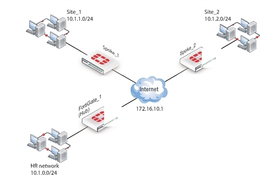
In the example configuration, the protected networks 10.1.0.0/24, 10.1.1.0/24 and 10.1.2.0/24 are all part of the larger subnet 10.1.0.0/16. The steps for setting up the example hub-and-spoke configuration create a VPN among Site 1, Site 2, and the HR Network.
The spokes are dialup. Their addresses are not part of the configuration on the hub, so only one spoke definition is required no matter the number of spokes. For simplicity, only two spokes are shown.
Configure the hub (FortiGate_1)
The Phase 1 configuration defines the parameters that FortiGate_1 will use to authenticate spokes and establish secure connections.
For the purposes of this example, one preshared key will be used to authenticate all of the spokes. Each key must contain at least 6 printable characters and best practices dictates that it only be known by network administrators. For optimum protection against currently known attacks, each key must consist of a minimum of 16 randomly chosen alphanumeric characters.
Define the IPsec configuration
To define the Phase 1 parameters
- At FortiGate_1, go to VPN > IPsec > Tunnels and create the new custom tunnel or edit an existing tunnel.
- Edit the Phase 1 Proposal (if it is not available, you may need to click the Convert to Custom Tunnel button).
Define the Phase 1 parameters that the hub will use to establish a secure connection to the spokes.
| Name | Enter a name (for example, toSpokes). |
| Remote Gateway | Dialup user |
| Local Interface | External |
| Mode | Main |
| Authentication Method | Preshared Key |
| Pre-shared Key | Enter the preshared key. |
| Peer Options | Any peer ID |
The basic Phase 2 settings associate IPsec Phase 2 parameters with the Phase 1 configuration and specify the remote end points of the VPN tunnels.
To define the Phase 2 parameters
- Open the Phase 2 Selectors panel (if it is not available, you may need to click the Convert to Custom Tunnel button).
- Enter the following information, and select OK:
| Name | Enter a name for the Phase 2 definition (for example, toSpokes_ph2). |
| Phase 1 | Select the Phase 1 configuration that you defined previously (for example, toSpokes). |
Define the security policies
security policies control all IP traffic passing between a source address and a destination address. For a route-based VPN, the policies are simpler than for a policy-based VPN. Instead of an IPSEC policy, you use an ACCEPT policy with the virtual IPsec interface as the external interface.
Before you define security policies, you must first define firewall addresses to use in those policies. You need addresses for:
- The HR network behind FortiGate_1
- The aggregate subnet address for the protected networks
To define the IP address of the HR network behind FortiGate_1
- Go to Policy & Objects > Objects > Addresses.
- Select Create New, enter the following information, and select OK:
| Name | Enter an address name (for example, HR_Network). |
| Type | Subnet |
| Subnet/IP Range | Enter the IP address of the HR network behind FortiGate_1 (for example, 10.1.0.0/24). |
To specify the IP address the aggregate protected subnet
- Go to Policy & Objects > Objects > Addresses.
- Select Create New, enter the following information, and select OK:
| Address Name | Enter an address name (for example, Spoke_net). |
| Type | Subnet |
| Subnet/IP Range | Enter the IP address of the aggregate protected network, 10.1.0.0/16 |
To define the security policy for traffic from the hub to the spokes
- Go to Policy & Objects > Policy > IPv4 and select Create New,
- Leave the Policy Type as Firewall and leave the Policy Subtype as Address.
- Enter the following information, and select OK:
| Incoming Interface | Select the interface to the HR network, port 1. |
| Source Address | Select HR_Network. |
| Outgoing Interface | Select the virtual IPsec interface that connects to the spokes, toSpokes. |
| Destination Address | Select Spoke_net. |
| Action | Select ACCEPT. |
Place the policy in the policy list above any other policies having similar source and destination addresses.
Configure communication between spokes
Spokes communicate with each other through the hub. You need to configure the hub to allow this communication. An easy way to do this is to create a zone containing the virtual IPsec interfaces even if there is only one, and create a zone-to-zone security policy.
To create a zone for the VPN
- Go to System > Network > Interfaces.
- Select the down-arrow on the Create New button and select Zone.
- In the Zone Name field, enter a name, such as
Our_VPN_zone. - Select Block intra-zone traffic.
You could enable intra-zone traffic and then you would not need to create a security policy. But, you would not be able to apply UTM features. - In Interface Members, select the virtual IPsec interface,
toSpokes. - Select OK.
To create a security policy for the zone
- Go to Policy & Objects > Policy > IPv4 and select Create New.
- Leave the Policy Type as Firewall and leave the Policy Subtype as Address.
- Enter these settings:
| Incoming Interface | Select Our_VPN_zone. |
| Source Address | Select All. |
| Outgoing Interface | Select Our_VPN_zone. |
| Destination Address | Select All. |
| Action | Select ACCEPT. |
| Enable NAT | Enable. |
- Select OK.
Configure the spokes
In this example, all spokes have nearly identical configuration, requiring the following:
- Phase 1 authentication parameters to initiate a connection with the hub.
- Phase 2 tunnel creation parameters to establish a VPN tunnel with the hub.
- A source address that represents the network behind the spoke. This is the only part of the configuration that is different for each spoke.
- A destination address that represents the aggregate protected network.
- A security policy to ena.ble communications between the spoke and the aggregate protected network
Define the IPsec configuration
At each spoke, create the following configuration.
To define the Phase 1 parameters
- At the spoke, go to VPN > IPsec > Tunnels and create the new custom tunnel or edit an existing tunnel.
- Edit the Phase 1 Proposal (if it is not available, you may need to click the Convert to Custom Tunnel button). Enter the following information:
| Name | Type a name, for example, toHub. |
| Remote Gateway | Select Static IP Address. |
| IP Address | Enter 172.16.10.1. |
| Local Interface | Select Port2. |
| Mode | Main |
| Authentication Method | Preshared Key |
| Pre-shared Key | Enter the preshared key. The value must be identical to the preshared key that you specified previously in the FortiGate_1 configuration |
| Peer Options | Select Any peer ID. |
To define the Phase 2 parameters
- Open the Phase 2 Selectors panel (if it is not available, you may need to click the Convert to Custom Tunnel button).
- Enter the following information and select OK:
| Name | Enter a name for the tunnel, for example, toHub_ph2. |
| Phase 1 | Select the name of the Phase 1 configuration that you defined previously, for example, toHub. |
| Advanced | Select to show the following Quick Mode Selector settings. |
| Source | Enter the address of the protected network at this spoke. For spoke_1, this is 10.1.1.0/24.For spoke_2, this is 10.1.2.0/24. |
| Destination | Enter the aggregate protected subnet address, 10.1.0.0/16. |
Define the security policies
You need to define firewall addresses for the spokes and the aggregate protected network and then create a security policy to enable communication between them.
To define the IP address of the network behind the spoke
- Go to Policy & Objects > Objects > Addresses.
- Select Create New and enter the following information:
| Address Name | Enter an address name, for example LocalNet. |
| Type | Subnet |
| Subnet/IP Range | Enter the IP address of the private network behind the spoke. For spoke_1, this is 10.1.1.0/24.For spoke_2, this is 10.1.2.0/24. |
To specify the IP address of the aggregate protected network
- Go to Policy & Objects > Objects > Addresses.
- Select Create New and enter the following information:
| Address Name | Enter an address name, for example, Spoke_net. |
| Type | Subnet |
| Subnet/IP Range | Enter the IP address of the aggregate protected network, 10.1.0.0/16. |
To define the security policy
- Go to Policy & Objects > Policy > IPv4 and select Create New.
- Leave the Policy Type as Firewall and leave the Policy Subtype as Address.
- Enter the following information:
| Incoming Interface | Select the virtual IPsec interface, toHub. |
| Source Address | Select the aggregate protected network address Spoke_net. |
| Outgoing Interface | Select the interface to the internal (private) network, port1. |
| Destination Address | Select the address for this spoke’s protected network LocalNet. |
| Action | Select ACCEPT. |
- Select Create New.
- Leave the Policy Type as Firewall and leave the Policy Subtype as Address.
- Enter the following information, and select OK:
| Incoming Interface | Select the interface to the internal private network, port1. |
| Source Address | Select the address for this spoke’s protected network, LocalNet. |
| Outgoing Interface | Select the virtual IPsec interface, toHub. |
| Destination Address | Select the aggregate protected network address, Spoke_net. |
| Action | Select ACCEPT. |
Place these policies in the policy list above any other policies having similar source and destination addresses.
Copyright © 2018 Fortinet, Inc. All Rights Reserved. | Terms of Service | Privacy Policy
