
FortiGate NP4 architectures
This chapter shows the NP4 architecture for the all FortiGate units and modules that include NP4 processors.
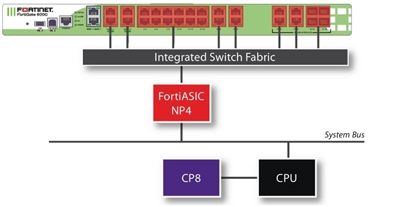
FortiGate-600C
The FortiGate-600C features one NP4 processor. All the ports are connected to this NP4 over the Integrated Switch Fabric. Port1 and port2 are dual failopen redundant RJ-45 ports. Port3-port22 are RJ-45 ethernet ports, and there are four 1Gb SFP interface ports duplicating the port19-port22 connections.
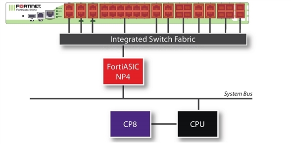
FortiGate-800C
The FortiGate-800C features one NP4 processor. All the ports are connected to this NP4. Port1 and port2 are dual failopen redundant RJ-45 ports. Port3-port22 are RJ-45 ethernet ports, and there are eight 1Gb SFP interface ports duplicating the port15-18 and port19-port22 connections. There are also two 10Gb SFP+ ports, port23 and port24.
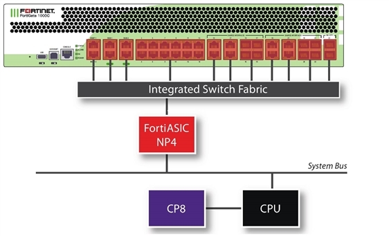
FortiGate-1000C
The FortiGate-1000C features one NP4 processor. All the ports are connected to this NP4. Port1 and port2 are dual failopen redundant RJ-45 ports. Port3-port22 are RJ-45 ethernet ports, and there are eight 1Gb SFP interface ports duplicating the port15-18 and port19-port22 connections. There are also two 10Gb SFP+ ports, port23 and port24.
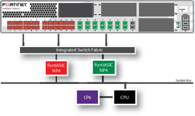
FortiGate-1240B
The FortiGate-1240B features two NP4 processors:
- Port1 to port24 are 1Gb SFP interfaces connected to one NP4 processor.
- Port25 to port38 are RJ-45 ethernet ports, connected to the other NP4 processor.
- Port39 and port40 are not connected to an NP4 processor.
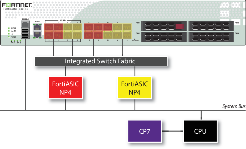
FortiGate-3040B
The FortiGate-3040B features two NP4 processors:
- The 10Gb interfaces, port1, port2, port3, port4, and the 1Gb interfaces, port9, port10, port11, port12, port13, share connections to one NP4 processor.
- The 10Gb interfaces, port5, port6, port7, port8, and the 1Gb interfaces, port14, port15, port16, port17, port18, share connections to the other NP4 processor.
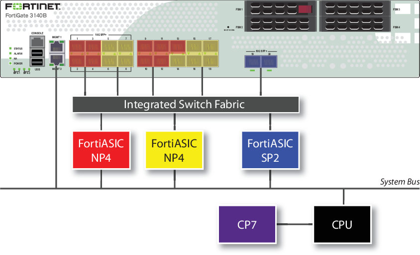
FortiGate-3140B
The FortiGate-3140B features two NP4 processors and one SP2 processor:
- The 10Gb interfaces, port1, port2, port3, port4, and the 1Gb interfaces, port9, port10, port11, port12, port13, share connections to one NP4 processor.
- The 10Gb interfaces, port5, port6, port7, port8, and the 1Gb interfaces, port14, port15, port16, port17, port18, share connections to the other NP4 processor.
- The 10Gb interfaces, port19 and port20, share connections to the SP2 processor.
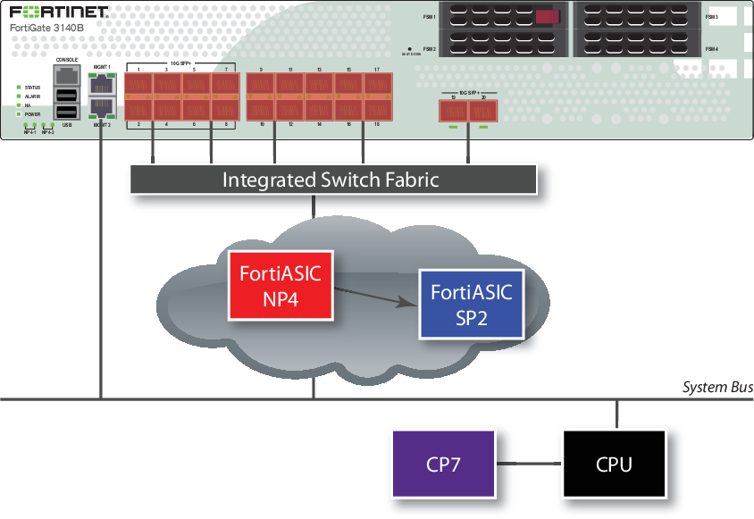
FortiGate-3140B — load balance mode
The FortiGate-3140B load balance mode allows you increased flexibility in how you use the interfaces on the FortiGate unit. When enabled, traffic between any two interfaces (excluding management and console) is accelerated. Traffic is not limited to entering and leaving the FortiGate unit in specific interface groupings to benefit from NP4 and SP2 acceleration. You can use any pair of interfaces.
Security acceleration in this mode is limited, however. Only IPS scanning is accelerated in load balance mode.
To enable this feature, issue this CLI command.
config system global
set sp-load-balance enable
end
The FortiGate unit will then restart.
To return to the default mode, issue this CLI command.
config system global
set sp-load-balance disable
end
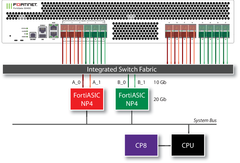
FortiGate-3240C
The FortiGate-3240C features two NP4 processors:
- The 10Gb interfaces, port1 through port6, and the 1Gb interfaces, port13 through port20, share connections to one NP4 processor.
- The 10Gb interfaces, port7 through port12, and the 1Gb interfaces, port21 through port28, share connections to the other NP4 processor.
In addition to the ports being divided between the two NP4 processors, they are further divided between the two connections to each processor. Each NP4 can process 20 Gb of network traffic per second and each of two connections to each NP4 can move 10Gb of data to the processor per second, so the ideal configuration would have no more than 10 Gb of network traffic to each connection of each NP4 at any time.
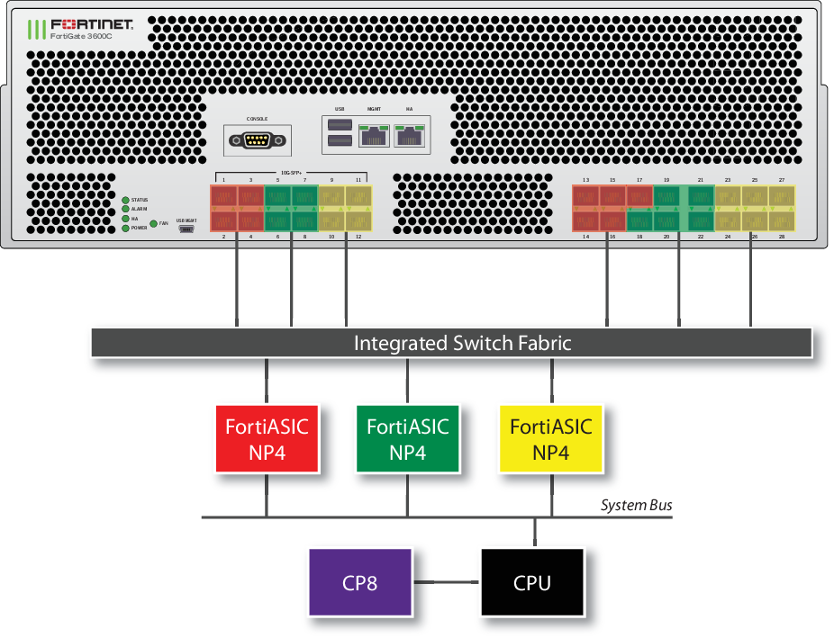
FortiGate-3600C
The FortiGate-3600C features three NP4 processors:
- The 10Gb interfaces, port1-port4, and the 1Gb interfaces, port13-port17, share connections to one NP4 processor.
- The 10Gb interfaces, port5-port8, and the 1Gb interfaces, port18-port22 share connections to the second NP4 processor.
- The 10Gb interfaces, port9-port12, and the 1Gb interfaces, port23-port28 share connections to the third NP4 processor.
FortiGate-3600C XAUI interfaces
The FortiGate-3600C uses XAUI links for communication between physical Ethernet ports and the integrated switch fabric.
Each XAUI link has a maximum bandwidth of 10-Gigabits. The reason you may need to know about the XAUI link in NP4 configurations is because of this 10-Gigabit limit. Because of this limitation, the total amount of data processed by all Ethernet interfaces connected to an XAUI link cannot exceed 10 gigabits. In some cases this may limit the amount of bandwidth that the FortiGate can process.
Each NP4 processor connects to the integrated switch fabric through two XAUI links: XAUI0 and XAUI1. All of the odd numbered Ethernet interfaces use XAU0 and all of the even numbered interfaces use XAUI1:
NPU1
XAUI0 = port1,port3,port13, port15, port17
XAUI1 = port2, port4, port14, port16
NPU2
XAUI0 = port5, port7, port18, port20, port22
XAUI1 = port6, port8, port19, port21
NPU3
XAUI0 = port9, port11, port23, port25, port27
XAUI1 = port10, port12, port24, port26, port28
Usually you do not have to be concerned about XAUI link mapping. However, if a FortiGate-3600C NP4 interface is processing a very high amount of traffic you should distribute that traffic among both of the XAUI links connected to it. So if you have a very high volume of traffic flowing between two networks you should connect both networks to the same NP4 processor but to different XAUI links. For example, you could connect one network to Etherent port5 and the other network to Ethernet port6. In this configuration, the second NP4 processor would handle traffic acceleration and both XAUI links would be processing traffic.
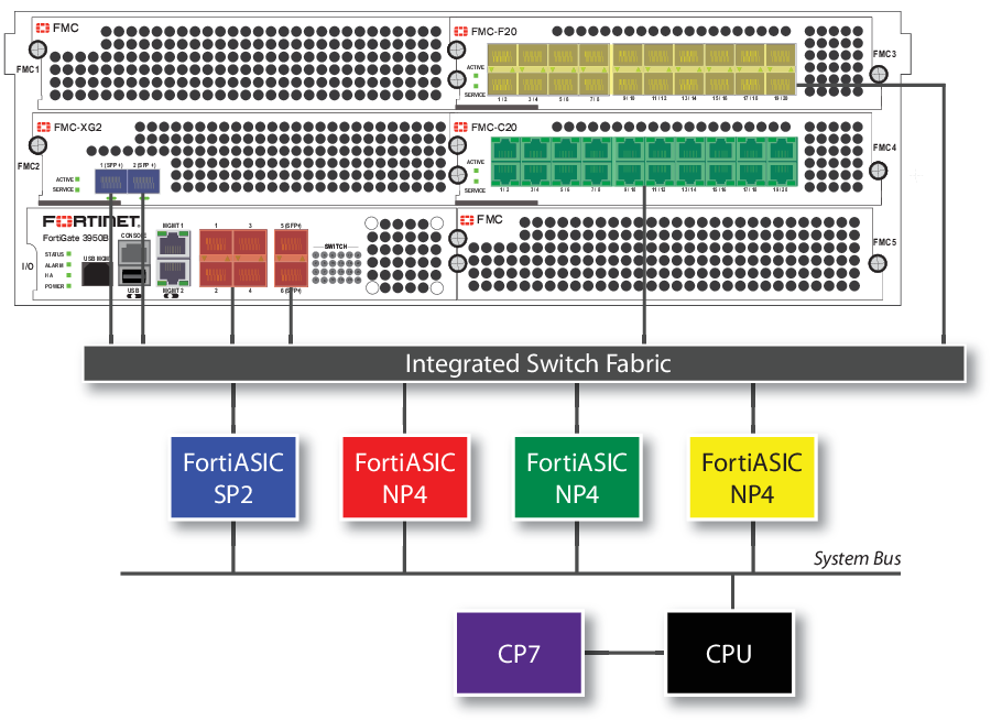
FortiGate-3950B and FortiGate-3951B
The FortiGate-3950B features one NP4 processor. The 1Gb SPF interfaces, port1, port2, port3, port4, and the 10Gb SPF+ interfaces, port5, port6, share connections to one NP4 processor. The FortiGate-3951B is similar to the FortiGate-3950B, except it trades one FMC slot for four FSM slots. The network interfaces available on each model are identical.
You can add additional FMC interface modules. The diagram below shows a FortiGate-3950B with three modules installed: an FMC-XG2, an FMC-F20, and an FMC-C20.
- The FMC-XG2 has one SP2 processor. The 10Gb SPF+ interfaces, port1 and port2, share connections to the processor.
- The FMC-F20 has one NP4 processor and the twenty 1Gb SPF interfaces, port1 through port20, share connections to the NP4 processor.
- The FMC-C20 has one NP4 processor and the twenty 10/100/1000 interfaces, port1 through port20, share connections to the NP4 processor.
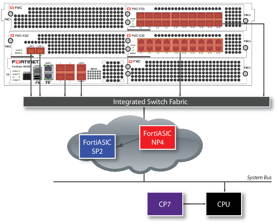
FortiGate-3950B and FortiGate-3951B — load balance mode
Adding one or more FMC-XG2 modules to your FortiGate-3950B allows you to enable load balance mode. This feature allows you increased flexibility in how you use the interfaces on the FortiGate unit. The FortiGate-3951B is similar to the FortiGate-3950B, except it trades one FMC slot for four FSM slots. The network interfaces available on each model are identical.
When enabled, traffic between any two interfaces (excluding management and console) is accelerated whether they are the six interfaces on the FortiGate-3950B itself, or on any installed FMC modules. Traffic is not limited to entering and leaving the FortiGate unit in specific interface groupings to benefit from NP4 and SP2 acceleration. You can use any pair of interfaces.
Security acceleration in this mode is limited, however. Only IPS scanning is accelerated in load balance mode.
The FortiGate-3950B in load balance mode
To enable this feature, issue this CLI command.
config system global
set sp-load-balance enable
end
The FortiGate unit will then restart.
To return to the default mode, issue this CLI command.
config system global
set sp-load-balance disable
end
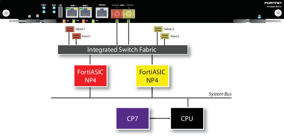
FortiGate-5001C
The FortiGate-5001C board includes two NP4 processors connected to an integrated switch fabric:
- The port1, fabric1, and base1 interfaces are connected to one NP4 processor.
- The port2, fabric2, and base2 interfaces are connected to the other NP4 processor.
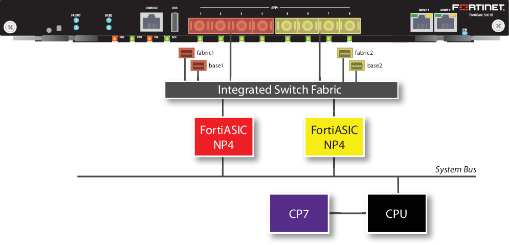
FortiGate-5001B
The FortiGate-5001B board includes two NP4 connected to an integrated switch fabric.
- The port1, port2, port3, port4, fabric1 and base1 interfaces are connected to one NP4 processor.
- The port5, port6, port7, port8, fabric2 and base2 interfaces are connected to the other NP4 processor.
Setting switch-mode mapping on the ADM-XD4
The ADM-XD4 SP has four 10Gb/s ports, but the NP4 processor it contains has only two 10Gb/s ports. The external ports you use are important to optimize the SP for your application.
ADM-XD4 mapping mode
Ports 1 and 3 share one NP4 processor and ports 2 and 4 share the other. Performance ports sharing the same NP4 processor is far better than when forcing network data to move between NP4 processors by using one port from each, for example ports 1 and 2 or ports 3 and 4.
Copyright © 2018 Fortinet, Inc. All Rights Reserved. | Terms of Service | Privacy Policy
