
Virtual Domains in NAT/Route mode
Virtual domains (VDOMs) are a method of dividing a FortiGate unit into two or more virtual units that each function as independent units. Each virtual domain has separate routing and security policies. A single FortiGate unit with virtual domains is flexible enough to serve multiple departments of an organization, separate organizations, or be the basis for a service provider’s managed security service.
|
|
The examples in this chapter are intended to be followed in order as procedures build on previous procedures. If you do not complete the previous procedures, the procedure you are working on may not work properly. If this happens, consult previous procedures or FortiGate documentation. |
This chapter contains the following sections:
- Virtual domains in NAT/Route mode
- Example NAT/Route VDOM configuration
- Figure 9: Example VDOM configuration
Virtual domains in NAT/Route mode
Once you have enabled virtual domains and created one or more VDOMs, you need to configure them. Configuring VDOMs on your FortiGate unit includes tasks such as the ones listed here; while you may not require all for your network topology, it is recommended that you perform them in the order given:
- Changing the management virtual domain
- Configuring interfaces in a NAT/Route VDOM
- Configuring VDOM routing
- Configuring security policies for NAT/Route VDOMs
- Configuring security profiles for NAT/Route VDOMs
Changing the management virtual domain
The management virtual domain is the virtual domain where all the management traffic for the FortiGate unit originates. This management traffic needs access to remote servers, such as FortiGuard services and NTP, to perform its duties. It needs access to the Internet to send and receive this traffic.
Management traffic includes, but is not limited to
- DNS lookups
- logging to FortiAnalyzer or syslog
- FortiGuard service
- sending alert emails
- Network time protocol traffic (NTP)
- Sending SNMP traps
- Quarantining suspicious files and email.
By default the management VDOM is the root domain. When other VDOMs are configured on your FortiGate unit, management traffic can be moved to one of these other VDOMs.
Reasons to move the management VDOM include selecting a non-root VDOM to be your administration VDOM, or the root VDOM not having an interface with a connection to the Internet.
|
|
You cannot change the management VDOM if any administrators are using RADIUS authentication. |
The following procedure will change the management VDOM from the default root to a VDOM named mgmt_vdom. It is assumed that mgmt_vdom has already been created and has an interface that can access the Internet.
To change the management VDOM - web-based manager:
- Select Global > VDOM > VDOM.
- Select the checkbox next to the required VDOM.
- Select Switch Management.
The current management VDOM is shown in square brackets, “[root]” for example.
To change the management VDOM - CLI:
config global
config system global
set management-vdom mgmt_vdom
end
Management traffic will now originate from mgmt_vdom.
Configuring interfaces in a NAT/Route VDOM
A VDOM must contain at least two interfaces to be useful. These can be physical interfaces or VLAN interfaces. By default, all physical interfaces are in the root VDOM. When you create a new VLAN, it is in the root VDOM by default.
When there are VDOMs on the FortiGate unit in both NAT and Transparent operation modes, some interface fields will be displayed as “-” on System > Network > Interfaces. Only someone with a super_admin account can view all the VDOMs.
|
|
When moving an interface to a different VDOM, firewall IP pools and virtual IPs for this interface are deleted. You should manually delete any routes that refer to this interface. Once the interface has been moved to the new VDOM, you can add these services to the interface again. |
|
|
When configuring VDOMs on FortiGate units with accelerated interfaces you must assign both interfaces in the pair to the same VDOM for those interfaces to retain their acceleration. Otherwise they will become normal interfaces. |
This section includes the following topics:
- Adding a VLAN to a NAT/Route VDOM
- Moving an interface to a VDOM
- Deleting an interface
- Adding a zone to a VDOM
Adding a VLAN to a NAT/Route VDOM
The following example shows one way that multiple companies can maintain their security when they are using one FortiGate unit with VLANs that share interfaces on the unit.
This procedure will add a VLAN interface called client1-v100 with a VLAN ID of 100 to an existing VDOM called client1 using the physical interface called port2.
|
|
The physical interface does not need to belong to the VDOM that the VLAN belongs to. |
To add a VLAN subinterface to a VDOM - web-based manager:
- Go to Global > Network > Interfaces.
- Select Create New.
- Enter the following information and select OK:
| Name | client1-v100 |
| Interface | port2 |
| VLAN ID | 100 |
| Virtual Domain | Client1 |
| Addressing mode | Manual |
| IP/Netmask | 172.20.120.110/255.255.255.0 |
| Administrative Access | HTTPS, SSH |
You will see an expand arrow added to the port2 interface. When the arrow is expanded, the interface shows the
client1-v100VLAN subinterface.
To add a VLAN subinterface to a VDOM - CLI:
config global
config system interface
edit client1-v100
set type vlan
set vlanid 100
set vdom Client1
set interface port2
set ip 172.20.120.110 255.255.255.0
set allowaccess https ssh
end
Moving an interface to a VDOM
Interfaces belong to the root VDOM by default. Moving an interface is the same procedure no matter if its moving from the root VDOM or a any other VDOM.
If you have an accelerated pair of physical interfaces both interfaces must be in the same VDOM or you will lose their acceleration.
The following procedure will move the port3 interface to the Client2 VDOM. This is a common action when configuring a VDOM. It is assumed that the Client2 VDOM has already been created. It is also assumed that your FortiGate unit has a port3 interface. If you are using a different model, your physical interfaces may not be named port2, external or port3.
To move an existing interface to a different VDOM - web-based manager:
- Go to Global > Network > Interfaces.
- Select Edit for the port3 interface.
- Select
Client2as the new Virtual Domain. - Select OK.
To move an existing interface to a different VDOM - CLI:
config global
config system interface
edit port3
set vdom Client2
end
Deleting an interface
Before you can delete a virtual interface, or move an interface from one VDOM to another, all references to that interface must be removed. For a list of objects that can refer to an interface see Per-VDOM settings - web-based manager.
The easiest way to be sure an interface can be deleted is when the Delete icon is no longer greyed out. If it remains greyed out when an interface is selected, that interface still has objects referring to it, or it is a physical interface that cannot be deleted.
To delete a virtual interface - web-based manager:
- Ensure all objects referring to this interface have been removed.
- Select Global > Network > Interfaces.
- Select the interface to delete.
- Select the delete icon.
Adding a zone to a VDOM
Grouping interfaces and VLAN subinterfaces into zones simplifies policy creation. You can configure policies for connections to and from a zone, but not between interfaces in a zone.
Zones are VDOM-specific. A zone cannot be moved to a different VDOM. Any interfaces in a zone cannot be used in another zone. To move a zone to a new VDOM requires deleting the current zone and re-creating a zone in the new VDOM.
The following procedure will create a zone called accounting in the client2 VDOM. It will not allow intra-zone traffic, and both port3 and port2 interfaces belong to this zone. This is a method of grouping and isolating traffic over particular interfaces—it is useful for added security and control within a larger network.
To add a zone to a VDOM - web-based manager:
- In Virtual Domains, select the client2 VDOM.
- Go to System > Network > Interfaces.
- Select Create New > Zone.
- Enter the following information and select OK:
| Zone Name | accounting |
| Block intra-zone traffic | Select |
| Interface Members | port3, port2 |
To add a zone to a VDOM - CLI:
config vdom
edit client2
config system zone
edit accounting
set interface port3 port2
set intrazone deny
end
end
Configuring VDOM routing
Routing is VDOM-specific. Each VDOM should have a default static route configured as a minimum. Within a VDOM, routing is the same as routing on your FortiGate unit without VDOMs enabled.
When configuring dynamic routing on a VDOM, other VDOMs on the FortiGate unit can be neighbors. The following topics give a brief introduction to the routing protocols, and show specific examples of how to configure dynamic routing for VDOMs. Figures are included to show the FortiGate unit configuration after the successful completion of the routing example.
This section includes:
Default static route for a VDOM
The routing you define applies only to network traffic entering non-ssl interfaces belonging to this VDOM. Set the administrative distance high enough, typically 20, so that automatically configured routes will be preferred to the default.
In the following procedure, it is assumed that a VDOM called “Client2” exists. The procedure will create a default static route for this VDOM. The route has a destination IP of 0.0.0.0, on the port3 interface. It has a gateway of 10.10.10.1, and an administrative distance of 20.
The values used in this procedure are very standard, and this procedure should be part of configuring all VDOMs.
To add a default static route for a VDOM - web-based manager:
- In Virtual Domains, select the client2 VDOM.
- Go to Router > Static > Static Routes.
- Select Create New.
- Enter the following information and select OK:
| Destination IP/Mask | 0.0.0.0/0.0.0.0 |
| Device | port2 |
| Gateway | 10.10.10.1 |
| Distance | 20 |
To add a default static route for a VDOM - CLI:
config vdom
edit client2
config router static
edit 4
set device port2
set dst 0.0.0.0 0.0.0.0
set gateway 10.10.10.1
set distance 20
end
end
Dynamic Routing in VDOMs
Dynamic routing is VDOM-specific, like all other routing. Dynamic routing configuration is the same with VDOMs as with your FortiGate unit without VDOMs enabled, once you are at the routing menu. If you have multiple VDOMs configured, the dynamic routing configuration between them can become quite complex.
VDOMs provide some interesting changes to dynamic routing. Each VDOM can be a neighbor to the other VDOMs. This is useful in simulating a dynamic routing area or AS or network using only your FortiGate unit.
You can separate different types of routing to different VDOMs if required. This allows for easier troubleshooting. This is very useful if your FortiGate unit is on the border of a number of different routing domains.
For more information on dynamic routing in FortiOS, see Dynamic Routing Overview.
Inter-VDOM links must have IP addresses assigned to them if they are part of a dynamic routing configuration. Inter-VDOM links may or may not have IP addresses assigned to them. Without IP addresses, you need to be careful how you configure routing. While the default static route can be assigned an address of 0.0.0.0 and rely instead on the interface, dynamic routing almost always requires an IP address.
RIP
The RIP dynamic routing protocol uses hop count to determine the best route, with a hop count of 1 being directly attached to the interface and a hop count of 16 being unreachable. For example if two VDOMs on the same FortiGate unit are RIP neighbors, they have a hop count of 1.
OSPF
OSPF communicates the status of its network links to adjacent neighbor routers instead of the complete routing table. When compared to RIP, OSPF is more suitable for large networks, it is not limited by hop count, and is more complex to configure. For smaller OSPF configurations its easiest to just use the backbone area, instead of multiple areas.
BGP
BGP is an Internet gateway protocol (IGP) used to connect autonomous systems (ASes) and is used by Internet service providers (ISPs). BGP stores the full path, or path vector, to a destination and its attributes which aid in proper routing.
Configuring security policies for NAT/Route VDOMs
Security policies are VDOM-specific. This means that all firewall settings for a VDOM, such as firewall addresses and security policies, are configured within the VDOM.
In VDOMs, all firewall related objects are configured per-VDOM including addresses, service groups, security profiles, schedules, traffic shaping, and so on. If you want firewall addresses, you will have to create them on each VDOM separately. If you have many addresses, and VDOMs this can be tedious and time consuming. Consider using a FortiManager unit to manage your VDOM configuration — it can get firewall objects from a configured VDOM or FortiGate unit, and push those objects to many other VDOMs or FortiGate units. See the FortiManager Administration Guide.
|
|
You can customize the Policy display by including some or all columns, and customize the column order onscreen. Due to this feature, security policy screenshots may not appear the same as on your screen. |
Configuring a security policy for a VDOM
Your security policies can involve only the interfaces, zones, and firewall addresses that are part of the current VDOM, and they are only visible when you are viewing the current VDOM. The security policies of this VDOM filter the network traffic on the interfaces and VLAN subinterfaces in this VDOM.
A firewall service group can be configured to group multiple services into one service group. When a descriptive name is used, service groups make it easier for an administrator to quickly determine what services are allowed by a security policy.
In the following procedure, it is assumed that a VDOM called Client2 exists. The procedure will configure an outgoing security policy. The security policy will allow all HTTPS and SSH traffic for the SalesLocal address group on VLAN_200 going to all addresses on port3. This traffic will be scanned and logged.
To configure a security policy for a VDOM - web-based manager:
- In Virtual Domains, select the client2 VDOM.
- Go to Policy > Policy.
- Select Create New.
- Enter the following information and select OK:
| Source Interface/Zone | VLAN_200 |
| Source Address | SalesLocal |
| Destination Interface/Zone | port3 |
| Destination Address | any |
| Schedule | always |
| Service | Multiple - HTTPS, SSH |
| Action | ACCEPT |
| Log Allowed Traffic | enable |
To configure a security policy for a VDOM - CLI:
config vdom
edit Client2
config firewall policy
edit 12
set srcintf VLAN_200
set srcaddr SalesLocal
set dstintf port3(dmz)
set dstaddr any
set schedule always
set service HTTPS SSH
set action accept
set status enable
set logtraffic enable
end
end
Configuring security profiles for NAT/Route VDOMs
In NAT/Route VDOMs, security profiles are exactly like regular FortiGate unit operation with one exception. In VDOMs, there are no default security profiles.
If you want security profiles in VDOMs, you must create them yourself. If you have many security profiles to create in each VDOM, you should consider using a FortiManager unit. It can get existing profiles from a VDOM or FortiGate unit, and push those profiles down to multiple other VDOMs or FortiGate units. See the FortiManager Administration Guide.
When VDOMs are enabled, you only need one FortiGuard license for the physical unit, and download FortiGuard updates once for the physical unit. This can result in a large time and money savings over multiple physical units if you have many VDOMs.
Configuring VPNs for a VDOM
Virtual Private Networking (VPN) settings are VDOM-specific, and must be configured within each VDOM. Configurations for IPsec Tunnel, IPsec Interface, PPTP and SSL are VDOM-specific. However, certificates are shared by all VDOMs and are added and configured globally to the FortiGate unit.
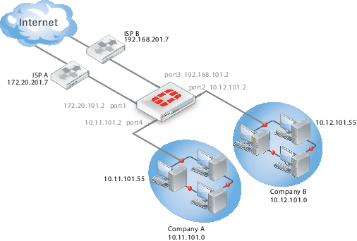
Example NAT/Route VDOM configuration
Company A and Company B each have their own internal networks and their own ISPs. They share a FortiGate unit that is configured with two separate VDOMs, with each VDOM running in NAT/Route mode enabling separate configuration of network protection profiles. Each ISP is connected to a different interface on the FortiGate unit.
This network example was chosen to illustrate one of the most typical VDOM configurations.
This example has the following sections:
- Network topology and assumptions
- General configuration steps
- Creating the VDOMs
- Configuring the FortiGate interfaces
- Configuring the vdomA VDOM
- Configuring the vdomB VDOM
- Testing the configuration
Network topology and assumptions
Both companies have their own ISPs and their own internal interface, external interface, and VDOM on the FortiGate unit.
For easier configuration, the following IP addressing is used:
- all IP addresses on the FortiGate unit end in “.2” such as 10.11.101.2.
- all IP addresses for ISPs end in “.7”, such as 172.20.201.7.
- all internal networks are 10.*.*.* networks, and sample internal addresses end in “.55”.
The IP address matrix for this example is as follows.
| Address | Company A | Company B |
|---|---|---|
| ISP | 172.20.201.7
|
192.168.201.7
|
| Internal network | 10.11.101.0
|
10.12.101.0
|
| FortiGate / VDOM | 172.20.101.2 (port1)
10.11.101.2 (port4)
|
192.168.201.2 (port3)
10.12.101.2 (port2)
|
The Company A internal network is on the 10.11.101.0/255.255.255.0 subnet. The Company B internal network is on the 10.12.101.0/255.255.255.0 subnet.
There are no switches or routers required for this configuration.
There are no VLANs in this network topology.
The interfaces used in this example are port1 through port4. Different FortiGate models may have different interface labels. port1 and port3 are used as external interfaces. port2 and port4 are internal interfaces.
The administrator is a super_admin account. If you are a using a non-super_admin account, refer to "Global and per-VDOM settings" to see which parts a non-super_admin account can also configure.
When configuring security policies in the CLI always choose a policy number that is higher than any existing policy numbers, select services before profile-status, and profile-status before profile. If these commands are not entered in that order, they may not be available to enter.
Figure 9: Example VDOM configuration
General configuration steps
For best results in this configuration, follow the procedures in the order given. Also, note that if you perform any additional actions between procedures, your configuration may have different results.
- Creating the VDOMs
- Configuring the FortiGate interfaces
- Configuring the vdomA VDOM, and Configuring the vdomB VDOM
- Testing the configuration
Creating the VDOMs
In this example, two new VDOMs are created — vdomA for Company A and vdomB for Company B. These VDOMs will keep the traffic for these two companies separate while enabling each company to access its own ISP.
To create two VDOMs - web-based manager:
- Log in with a super_admin account.
- Go to Global > VDOM > VDOM, and select Create New.
- Enter
vdomAand select OK. - Select OK again to return to the VDOM list.
- Select Create New.
- Enter
vdomBand select OK.
To create two VDOMs - CLI:
config vdom
edit vdomA
next
edit vdomB
end
Configuring the FortiGate interfaces
This section configures the interfaces that connect to the companies’ internal networks, and to the companies’ ISPs.
All interfaces on the FortiGate unit will be configured with an IP address ending in “.2” such as 10.11.101.2. This will simplify network administration both for the companies, and for the FortiGate unit global administrator. Also the internal addresses for each company differ in the second octet of their IP address - Company A is 10.11.*, and Company B is 10.12.*.
This section includes the following topics:
|
|
If you cannot change the VDOM of an network interface it is because something is referring to that interface that needs to be deleted. Once all the references are deleted the interface will be available to switch to a different VDOM. For example a common reference to the external interface is the default static route entry. See Configuring interfaces in a NAT/Route VDOM. |
Configuring the vdomA interfaces
The vdomA VDOM includes two FortiGate unit interfaces: port1 and external.
The port4 interface connects the Company A internal network to the FortiGate unit, and shares the internal network subnet of 10.11.101.0/255.255.255.0.
The external interface connects the FortiGate unit to ISP A and the Internet. It shares the ISP A subnet of 172.20.201.0/255.255.255.0.
To configure the vdomA interfaces - web-based manager:
- Go to Global > Network > Interfaces.
- Select Edit on the port1 interface.
- Enter the following information and select OK:
| Virtual Domain | vdomA |
| Addressing mode | Manual |
| IP/Netmask | 172.20.101.2/255.255.255.0 |
- Select Edit on the port4 interface.
- Enter the following information and select OK:
| Virtual Domain | vdomA |
| Addressing mode | Manual |
| IP/Netmask | 10.11.101.2/255.255.255.0 |
To configure the vdomA interfaces - CLI:
config global
config system interface
edit port1
set vdom vdomA
set mode static
set ip 172.20.101.2 255.255.255.0
next
edit port4
set vdom vdomA
set mode static
set ip 10.11.101.2 255.255.255.0
end
Configuring the vdomB interfaces
The vdomB VDOM uses two FortiGate unit interfaces: port2 and port3.
The port2 interface connects the Company B internal network to the FortiGate unit, and shares the internal network subnet of 10.12.101.0/255.255.255.0.
The port3 interface connects the FortiGate unit to ISP B and the Internet. It shares the ISP B subnet of 192.168.201.0/255.255.255.0.
To configure the vdomB interfaces - web-based manager:
- Go to Global > Network > Interfaces.
- Select Edit on the port3 interface.
- Enter the following information and select OK:
| Virtual domain | vdomB |
| Addressing mode | Manual |
| IP/Netmask | 192.168.201.2/255.255.255.0 |
- Select Edit on the port2 interface.
- Enter the following information and select OK:
| Virtual domain | vdomB |
| Addressing mode | Manual |
| IP/Netmask | 10.12.101.2/255.255.255.0 |
To configure the vdomB interfaces - CLI:
config global
config system interface
edit port3
set vdom vdomB
set mode static
set ip 192.168.201.2 255.255.255.0
next
edit port2
set vdom vdomB
set mode static
set ip 10.12.101.2 255.255.255.0
end
Configuring the vdomA VDOM
With the VDOMs created and the ISPs connected, the next step is to configure the vdomA VDOM.
Configuring the vdomA includes the following:
Adding vdomA firewall addresses
You need to define the addresses used by Company A’s internal network for use in security policies. This internal network is the 10.11.101.0/255.255.255.0 subnet.
The FortiGate unit provides one default address, “all”, that you can use when a security policy applies to all addresses as the source or destination of a packet.
To add the vdomA firewall addresses - web-based manager:
- In Virtual Domains, select vdomA.
- Go to Firewall Objects > Address > Address.
- Select Create New.
- Enter the following information and select OK:
| Address Name | Ainternal |
| Type | Subnet / IP Range |
| Subnet / IP Range | 10.11.101.0/255.255.255.0 |
| Interface | port4 |
To add the vdomA VDOM firewall addresses - CLI:
config vdom
edit vdomA
config firewall address
edit Ainternal
set type ipmask
set subnet 10.11.101.0 255.255.255.0
end
end
Adding the vdomA security policy
You need to add the vdomA security policy to allow traffic from the internal network to reach the external network, and from the external network to internal as well. You need two policies for this domain.
To add the vdomA security policy - web-based manager:
- In Virtual Domains, select vdomA.
- Go to Policy > Policy.
- Select Create New.
- Enter the following information and select OK:
| Source Interface/Zone | port4 |
| Source Address | Ainternal |
| Destination Interface/Zone | port1 |
| Destination Address | all |
| Schedule | Always |
| Service | ANY |
| Action | ACCEPT |
- Select Create New.
- Enter the following information and select OK:
| Source Interface/Zone | port1 |
| Source Address | all |
| Destination Interface/Zone | port4 |
| Destination Address | Ainternal |
| Schedule | Always |
| Service | ANY |
| Action | ACCEPT |
To add the vdomA security policy - CLI:
config vdom
edit vdomA
config firewall policy
edit 1
set srcintf port4
set srcaddr Ainternal
set dstintf port1
set dstaddr all
set schedule always
set service ANY
set action accept
set status enable
next
edit 2
set srcintf port1
set srcaddr all
set dstintf port4
set dstaddr Ainternal
set schedule always
set service ANY
set action accept
set status enable
end
Adding the vdomA default route
You also need to define a default route to direct packets from the Company A internal network to ISP A. Every VDOM needs a default static route, as a minimum, to handle traffic addressed to external networks such as the Internet.
The administrative distance should be set slightly higher than other routes. Lower admin distances will get checked first, and this default route will only be used as a last resort.
To add a default route to the vdomA - web-based manager:
- For Virtual Domains, select vdomA
- Go to Router > Static > Static Routes.
- Select Create New.
- Enter the following information and select OK:
| Destination IP/Mask | 0.0.0.0/0.0.0.0 |
| Device | port1 |
| Gateway | 172.20.201.7 |
| Distance | 20 |
To add a default route to the vdomA - CLI:
config vdom
edit vdomA
config router static
edit 1
set device port1
set gateway 172.20.201.7
end
Configuring the vdomB VDOM
In this example, the vdomB VDOM is used for Company B. Firewall and routing settings are specific to a single VDOM.
vdomB includes the FortiGate port2 interface to connect to the Company B internal network, and the FortiGate port3 interface to connect to ISP B. Security policies are needed to allow traffic from port2 to external and from external to port2 interfaces.
This section includes the following topics:
- Adding the vdomB firewall address
- Adding the vdomB security policy
- Adding a default route to the vdomB VDOM
Adding the vdomB firewall address
You need to define addresses for use in security policies. In this example, the vdomB VDOM needs an address for the port2 interface and the “all” address.
To add the vdomB firewall address - web-based manager:
- In Virtual Domains, select vdomB.
- Go to Firewall Objects > Address > Address.
- Select Create New.
- Enter the following information and select OK:
| Address Name | Binternal |
| Type | Subnet / IP Range |
| Subnet / IP Range | 10.12.101.0/255.255.255.0 |
| Interface | port2 |
To add the vdomB firewall address - CLI:
config vdom
edit vdomB
config firewall address
edit Binternal
set type ipmask
set subnet 10.12.101.0 255.255.255.0
end
end
Adding the vdomB security policy
You also need a security policy for the Company B domain. In this example, the security policy allows all traffic.
To add the vdomB security policy - web-based manager:
- Log in with a super_admin account.
- In Virtual Domains, select vdomB.
- Go to Policy > Policy.
- Select Create New.
- Enter the following information and select OK:
| Source Interface/Zone | port2 |
| Source Address | Binternal |
| Destination Interface/Zone | port3 |
| Destination Address | all |
| Schedule | Always |
| Service | ANY |
| Action | ACCEPT |
- Select Create New.
- Enter the following information and select OK:
| Source Interface/Zone | port3 |
| Source Address | all |
| Destination Interface/Zone | port2 |
| Destination Address | Binternal |
| Schedule | Always |
| Service | ANY |
| Action | ACCEPT |
To add the vdomB security policy - CLI:
config vdom
edit vdomB
config firewall policy
edit 1
set srcintf port2
set dstintf port3
set srcaddr Binternal
set dstaddr all
set schedule always
set service ANY
set action accept
set status enable
edit 1
set srcintf port3
set dstintf port2
set srcaddr all
set dstaddr Binternal
set schedule always
set service ANY
set action accept
set status enable
end
end
Adding a default route to the vdomB VDOM
You need to define a default route to direct packets to ISP B.
To add a default route to the vdomB VDOM - web-based manager:
- Log in as the super_admin administrator.
- In Virtual Domains, select vdomB.
- Go to Router > Static > Static Routes.
- Select Create New.
- Enter the following information and select OK:
| Destination IP/Mask | 0.0.0.0/0.0.0.0 |
| Device | port3 |
| Gateway | 192.168.201.7 |
| Distance | 20 |
To add a default route to the vdomB VDOM - CLI:
config vdom
edit vdomB
config router static
edit 1
set dst 0.0.0.0/0
set device external
set gateway 192.168.201.7
end
end
Testing the configuration
Once you have completed configuration for both company VDOMs, you can use diagnostic commands, such as tracert in Windows, to test traffic routed through the FortiGate unit. Alternately, you can use the traceroute command on a Linux system with similar output.
Possible errors during the traceroute test are:
- “
* * * Request timed out” - the trace was not able to make the next connection towards the destination fast enough - “
Destination host unreachable” - after a number of timed-out responses the trace will give up
Possible reasons for these errors are bad connections or configuration errors.
For additional troubleshooting, see Troubleshooting Virtual Domains.
Testing traffic from the internal network to the ISP
In this example, a route is traced from the Company A internal network to ISP A. The test was run on a Windows PC with an IP address of 10.11.101.55.
The output here indicates three hops between the source and destination, the IP address of each hop, and that the trace was successful.
From the Company A internal network, access a command prompt and enter this command:
C:\>tracert 172.20.201.7
Tracing route to 172.20.201.7 over a maximum of 30 hops:
1 <10 ms <10 ms <10 ms 10.11.101.2
2 <10 ms <10 ms <10 ms 172.20.101.2
3 <10 ms <10 ms <10 ms 172.20.201.7
Trace complete.
Copyright © 2018 Fortinet, Inc. All Rights Reserved. | Terms of Service | Privacy Policy
