
HA and failover protection
In FortiGate active-passive HA, the FortiGate Clustering Protocol (FGCP) provides failover protection. This means that an active-passive cluster can provide FortiGate services even when one of the cluster units encounters a problem that would result in complete loss of connectivity for a stand-aloneFortiGate unit. This failover protection provides a backup mechanism that can be used to reduce the risk of unexpected downtime, especially in a mission-critical environment.
The FGCP supports three kinds of failover protection. Device failover automatically replaces a failed device and restarts traffic flow with minimal impact on the network. Link failover maintains traffic flow if a link fails. Session failover resumes communication sessions with minimal loss of data if a device or link failover occurs.
This chapter describes how FGCP failover protection works and provides detailed NAT/Route and Transparent mode packet flow descriptions.
About active-passive failover
To achieve failover protection in an active-passive cluster, one of the cluster units functions as the primary unit, while the rest of the cluster units are subordinate units, operating in an active stand-by mode. The cluster IP addresses and HA virtual MAC addresses are associated with the cluster interfaces of the primary unit. All traffic directed at the cluster is actually sent to and processed by the primary unit.
While the cluster is functioning, the primary unit functions as the FortiGate network security device for the networks that it is connected to. In addition, the primary unit and subordinate units use the HA heartbeat to keep in constant communication. The subordinate units report their status to the cluster unit and receive and store connection and state table updates.
Device failure
If the primary unit encounters a problem that is severe enough to cause it to fail, the remaining cluster units negotiate to select a new primary unit. This occurs because all of the subordinate units are constantly waiting to negotiate to become primary units. Only the heartbeat packets sent by the primary unit keep the subordinate units from becoming primary units. Each received heartbeat packet resets negotiation timers in the subordinate units. If this timer is allowed to run out because the subordinate units do not receive heartbeat packets from the primary unit, the subordinate units assume that the primary unit has failed, and negotiate to become primary units themselves.
Using the same FGCP negotiation process that occurs when the cluster starts up, after they determine that the primary unit has failed, the subordinate units negotiate amongst themselves to select a new primary unit. The subordinate unit that wins the negotiation becomes the new primary unit with the same MAC and IP addresses as the former primary unit. The new primary unit then sends gratuitous ARP packets out all of its interfaces to inform attached switches to send traffic to the new primary unit. Sessions then resume with the new primary unit.
Link failure
If a primary unit interface fails or is disconnected while a cluster is operation, a link failure occurs. When a link failure occurs the cluster units negotiate to select a new primary unit. Since the primary unit has not stopped operating, it participates in the negotiation. The link failure means that a new primary unit must be selected and the cluster unit with the link failure joins the cluster as a subordinate unit.
Just as for a device failover, the new primary unit sends gratuitous arp packets out all of its interfaces to inform attached switches to send traffic to it. Sessions then resume with the new primary unit.
If a subordinate unit experiences a device failure its status in the cluster does not change. However, in future negotiations a cluster unit with a link failure is unlikely to become the primary unit.
Session failover
If you enable session failover (also called session pickup) for the cluster, during cluster operation the primary unit informs the subordinate units of changes to the primary unit connection and state tables, keeping the subordinate units up-to-date with the traffic currently being processed by the cluster.
After a failover the new primary unit recognizes open sessions that were being handled by the cluster. The sessions continue to be processed by the new primary unit and are handled according to their last known state.
If you leave session pickup disabled, the cluster does not keep track of sessions and after a failover, active sessions have to be restarted or resumed.
Primary unit recovery
If a primary unit recovers after a device or link failure, it will operate as a subordinate unit, unless the override CLI keyword is enabled and its device priority is set higher than the unit priority of other cluster units (see HA override).
About active-active failover
HA failover in a cluster running in active-active mode is similar to active-passive failover described above. Active-active subordinate units are constantly waiting to negotiate to become primary units and, if session failover is enabled, continuously receive connection state information from the primary unit. If the primary unit fails, or one of the primary unit interfaces fails, the cluster units use the same mechanisms to detect the failure and to negotiate to select a new primary unit. If session failover is enabled, the new primary unit also maintains communication sessions through the cluster using the shared connection state table.
Active-active HA load balances sessions among all cluster units. For session failover, the cluster must maintain all of these sessions. To load balance sessions, the functioning cluster uses a load balancing schedule to distribute sessions to all cluster units. The shared connection state table tracks the communication sessions being processed by all cluster units (not just the primary unit). After a failover, the new primary unit uses the load balancing schedule to re-distribute all of the communication sessions recorded in the shared connection state table among all of the remaining cluster units. The connections continue to be processed by the cluster, but possibly by a different cluster unit, and are handled according to their last known state.
Device failover
The FGCP provides transparent device failover. Device failover is a basic requirement of any highly available system. Device failover means that if a device fails, a replacement device automatically takes the place of the failed device and continues operating in the same manner as the failed device.
In the case of FortiOS HA, the device is the primary unit. If the primary unit fails, device failover ensures that one of the subordinate units in the cluster automatically takes the place of the primary unit and can continue processing network traffic in the same way as the failed primary unit.
|
|
Device failover does not maintain communication sessions. After a device failover, communication sessions have to be restarted. To maintain communication sessions, you must enable session failover. See Session failover (session pick-up). |
FortiGate HA device failover is supported by the HA heartbeat, virtual MAC addresses, configuration synchronization, route synchronization and IPsec VPN SA synchronization.
The HA heartbeat makes sure that the subordinate units detect a primary unit failure. If the primary unit fails to respond on time to HA heartbeat packets the subordinate units assume that the primary unit has failed and negotiate to select a new primary unit.
The new primary unit takes the place of the failed primary unit and continues functioning in the same way as the failed primary unit. For the new primary unit to continue functioning like the failed primary unit, the new primary unit must be able to reconnect to network devices and the new primary unit must have the same configuration as the failed primary unit.
FortiGate HA uses virtual MAC addresses to reconnect the new primary unit to network devices. The FGCP causes the new primary unit interfaces to acquire the same virtual MAC addresses as the failed primary unit. As a result, the new primary unit has the same network identity as the failed primary unit.
The new primary unit interfaces have different physical connections than the failed primary unit. Both the failed and the new primary unit interfaces are connected to the same switches, but the new primary unit interfaces are connected to different ports on these switches. To make sure that the switches send packets to the new primary unit, the new primary unit interfaces send gratuitous ARP packets to the connected switches. These gratuitous ARP packets notify the switches that the primary unit MAC and IP addresses are on different switch ports and cause the switches to send packets to the ports connected to the new primary unit. In this way, the new primary unit continues to receive packets that would otherwise have been sent to the failed primary unit.
Configuration synchronization means that the new primary unit always has the same configuration as the failed primary unit. As a result the new primary unit operates in exactly the same way as the failed primary unit. If configuration synchronization were not available the new primary unit may not process network traffic in the same way as the failed primary unit.
Kernel routing table synchronization synchronizes the primary unit kernel routing table to all subordinate units so that after a failover the new primary unit does not have to form a completely new routing table. IPsec VPN SA synchronization synchronizes IPsec VPN security associations (SAs) and other IPsec session data so that after a failover the new primary unit can resume IPsec tunnels without having to establish new SAs.
HA heartbeat and communication between cluster units
The HA heartbeat keeps cluster units communicating with each other. The heartbeat consists of hello packets that are sent at regular intervals by the heartbeat interface of all cluster units. These hello packets describe the state of the cluster unit and are used by other cluster units to keep all cluster units synchronized.
HA heartbeat packets are non-TCP packets that use Ethertype values 0x8890, 0x8891, and 0x8890. The default time interval between HA heartbeats is 200 ms. The FGCP uses link-local IP4 addresses in the 169.254.0.x range for HA heartbeat interface IP addresses.
For best results, isolate the heartbeat devices from your user networks by connecting the heartbeat devices to a separate switch that is not connected to any network. If the cluster consists of two FortiGate units you can connect the heartbeat device interfaces directly using a crossover cable. Heartbeat packets contain sensitive information about the cluster configuration. Heartbeat packets may also use a considerable amount of network bandwidth. For these reasons, it is preferable to isolate heartbeat packets from your user networks.
On startup, a FortiGate unit configured for HA operation broadcasts HA heartbeat hello packets from its HA heartbeat interface to find other FortiGate units configured to operate in HA mode. If two or more FortiGate units operating in HA mode connect with each other, they compare HA configurations (HA mode, HA password, and HA group ID). If the HA configurations match, the units negotiate to form a cluster.
While the cluster is operating, the HA heartbeat confirms that all cluster units are functioning normally. The heartbeat also reports the state of all cluster units, including the communication sessions that they are processing.
Heartbeat interfaces
A heartbeat interface is an Ethernet network interface in a cluster that is used by the FGCP for HA heartbeat communications between cluster units.
To change the HA heartbeat configuration go to System > Config > HA and select the FortiGate interfaces to use as HA heartbeat interfaces.
|
|
Do not use a switch port for the HA heartbeat traffic. This configuration is not supported. |
From the CLI enter the following command to make port4 and port5 HA heartbeat interfaces and give both interfaces a heartbeat priority of 150:
config system ha
set hbdev port4 150 port5 150
end
The following example shows how to change the default heartbeat interface configuration so that the port4 and port1 interfaces can be used for HA heartbeat communication and to give the port4 interface the highest heartbeat priority so that port4 is the preferred HA heartbeat interface.
config system ha
set hbdev port4 100 port1 50
end
By default, for most FortiGate models two interfaces are configured to be heartbeat interfaces. You can change the heartbeat interface configuration as required. For example you can select additional or different heartbeat interfaces. You can also select only one heartbeat interface.
In addition to selecting the heartbeat interfaces, you also set the Priority for each heartbeat interface. In all cases, the heartbeat interface with the highest priority is used for all HA heartbeat communication. If the interface fails or becomes disconnected, the selected heartbeat interface that has the next highest priority handles all heartbeat communication.
If more than one heartbeat interface has the same priority, the heartbeat interface with the highest priority that is also highest in the heartbeat interface list is used for all HA heartbeat communication. If this interface fails or becomes disconnected, the selected heartbeat interface with the highest priority that is next highest in the list handles all heartbeat communication.
The default heartbeat interface configuration sets the priority of two heartbeat interfaces to 50. You can accept the default heartbeat interface configuration if one or both of the default heartbeat interfaces are connected. You can select different heartbeat interfaces, select more heartbeat interfaces and change heartbeat priorities according to your requirements.
For the HA cluster to function correctly, you must select at least one heartbeat interface and this interface of all of the cluster units must be connected together. If heartbeat communication is interrupted and cannot failover to a second heartbeat interface, the cluster units will not be able to communicate with each other and more than one cluster unit may become a primary unit. As a result the cluster stops functioning normally because multiple devices on the network may be operating as primary units with the same IP and MAC addresses creating a kind if split brain scenario.
The heartbeat interface priority range is 0 to 512. The default priority when you select a new heartbeat interface is 0. The higher the number the higher the priority.
In most cases you can maintain the default heartbeat interface configuration as long as you can connect the heartbeat interfaces together. Configuring HA heartbeat interfaces is the same for virtual clustering and for standard HA clustering.
You can enable heartbeat communications for physical interfaces, but not for VLAN subinterfaces, IPsec VPN interfaces, redundant interfaces, or for 802.3ad aggregate interfaces. You cannot select these types of interfaces in the heartbeat interface list.
Selecting more heartbeat interfaces increases reliability. If a heartbeat interface fails or is disconnected, the HA heartbeat fails over to the next heartbeat interface.
You can select up to 8 heartbeat interfaces. This limit only applies to FortiGate units with more than 8 physical interfaces.
HA heartbeat traffic can use a considerable amount of network bandwidth. If possible, enable HA heartbeat traffic on interfaces used only for HA heartbeat traffic or on interfaces connected to less busy networks.
Connecting HA heartbeat interfaces
For most FortiGate models if you do not change the heartbeat interface configuration, you can isolate the default heartbeat interfaces of all of the cluster units by connecting them all to the same switch. Use one switch per heartbeat interface. If the cluster consists of two units you can connect the heartbeat interfaces together using crossover cables.
HA heartbeat and data traffic are supported on the same cluster interface. In NAT/Route mode, if you decide to use heartbeat interfaces for processing network traffic or for a management connection, you can assign the interface any IP address. This IP address does not affect HA heartbeat traffic.
In Transparent mode, you can connect the heartbeat interface to your network and enable management access. You would then establish a management connection to the interface using the Transparent mode management IP address. This configuration does not affect HA heartbeat traffic.
Heartbeat packets and heartbeat interface selection
HA heartbeat hello packets are constantly sent by all of the enabled heartbeat interfaces. Using these hello packets, each cluster unit confirms that the other cluster units are still operating. The FGCP selects one of the heartbeat interfaces to be used for communication between the cluster units. The FGCP selects the heartbeat interface for heartbeat communication based on the linkfail states of the heartbeat interfaces, on the priority of the heartbeat interfaces, and on the interface index.
The FGCP checks the linkfail state of all heartbeat interfaces to determine which ones are connected. The FGCP selects one of these connected heartbeat interfaces to be the one used for heartbeat communication. The FGCP selects the connected heartbeat interface with the highest priority for heartbeat communication.
If more than one connected heartbeat interface has the highest priority the FGCP selects the heartbeat interface with the lowest interface index. The web-based manager lists the FortiGate unit interfaces in alphabetical order. This order corresponds to the interface index order with lowest index at the top and highest at the bottom. If more than one heartbeat interface has the highest priority, the FGCP selects the interface that is highest in the heartbeat interface list (or first in alphabetical order) for heartbeat communication.
If the interface that is processing heartbeat traffic fails or becomes disconnected, the FGCP uses the same criteria to select another heartbeat interface for heartbeat communication. If the original heartbeat interface is fixed or reconnected, the FGCP again selects this interface for heartbeat communication.
The HA heartbeat communicates cluster session information, synchronizes the cluster configuration, synchronizes the cluster kernel routing table, and reports individual cluster member status. The HA heartbeat constantly communicates HA status information to make sure that the cluster is operating properly.
Interface index and display order
The web-based manager and CLI display interface names in alphanumeric order. For example, the sort order for a FortiGate unit with 10 interfaces (named port1 through port10) places port10 at the bottom of the list:
- port1
- port2 through 9
- port10
However, interfaces are indexed in hash map order, rather than purely by alphabetic order or purely by interface number value comparisons. As a result, the list is sorted primarily alphabetical by interface name (for example, base1 is before port1), then secondarily by index numbers:
- port1
- port10
- port2 through port9
HA heartbeat interface IP addresses
The FGCP uses link-local IP4 addresses (RFC 3927) in the 169.254.0.x range for HA heartbeat interface IP addresses and for inter-VDOM link interface IP addresses. When a cluster initially starts up, the primary unit heartbeat interface IP address is 169.254.0.1. Subordinate units are assigned heartbeat interface IP addresses in the range 169.254.0.2 to 169.254.0.63. HA inter-VDOM link interfaces on the primary unit are assigned IP addresses 169.254.0.65 and 169.254.0.66.
The ninth line of the following CLI command output shows the HA heartbeat interface IP address of the primary unit.
get system ha status
Model: 620
Mode: a-p
Group: 0
Debug: 0
ses_pickup: disable
Master:150 head_office_upper FG600B3908600825 1
Slave :150 head_office_lower FG600B3908600705 0
number of vcluster: 1
vcluster 1: work 169.254.0.1
Master:0 FG600B3908600825
Slave :1 FG600B3908600705
You can also use the execute traceroute command from the subordinate unit CLI to display HA heartbeat IP addresses and the HA inter-VDOM link IP addresses. For example, use execute ha manage 1 to connect to the subordinate unit CLI and then enter the following command to trace the route to an IP address on your network:
execute traceroute 172.20.20.10
traceroute to 172.20.20.10 (172.20.20.10), 32 hops max, 72 byte packets
1 169.254.0.1 0 ms 0 ms 0 ms
2 169.254.0.66 0 ms 0 ms 0 ms
3 172.20.20.10 0 ms 0 ms 0 ms
Both HA heartbeat and data traffic are supported on the same FortiGate interface. All heartbeat communication takes place on a separate VDOM called vsys_ha. Heartbeat traffic uses a virtual interface called port_ha in the vsys_ha VDOM. Data and heartbeat traffic use the same physical interface, but they’re logically separated into separate VDOMs.
Heartbeat packet Ethertypes
Normal IP packets are 802.3 packets that have an Ethernet type (Ethertype) field value of 0x0800. Ethertype values other than 0x0800 are understood as level2 frames rather than IP packets.
By default, HA heartbeat packets use the following Ethertypes:
- HA heartbeat packets for NAT/Route mode clusters use Ethertype 0x8890. These packets are used by cluster units to find other cluster units and to verify the status of other cluster units while the cluster is operating. You can change the Ethertype of these packets using the
ha-eth-typeoption of theconfig system hacommand. - HA heartbeat packets for Transparent mode clusters use Ethertype 0x8891. These packets are used by cluster units to find other cluster units and to verify the status of other cluster units while the cluster is operating. You can change the Ethertype of these packets using the
hc-eth-typeoption of theconfig system hacommand. - HA telnet sessions between cluster units over HA heartbeat links use Ethertype 0x8893. The telnet sessions are used to synchronize the cluster configurations. Telnet sessions are also used when an administrator uses the
execute ha managecommand to connect from one cluster unit CLI to another. You can change the Ethertype of these packets using thel2ep-eth-typeoption of theconfig system hacommand.
Because heartbeat packets are recognized as level2 frames, the switches and routers on your heartbeat network that connect to heartbeat interfaces must be configured to allow them. If level2 frames are dropped by these network devices, heartbeat traffic will not be allowed between the cluster units.
Some third-party network equipment may use packets with these Ethertypes for other purposes. For example, Cisco N5K/Nexus switches use Ethertype 0x8890 for some functions. When one of these switches receives Ethertype 0x8890 packets from an attached cluster unit, the switch generates CRC errors and the packets are not forwarded. As a result, FortiGate units connected with these switches cannot form a cluster.
In some cases, if the heartbeat interfaces are connected and configured so regular traffic flows but heartbeat traffic is not forwarded, you can change the configuration of the switch that connects the HA heartbeat interfaces to allow level2 frames with Ethertypes 0x8890, 0x8893, and 0x8891 to pass.
Alternatively, you can use the following CLI options to change the Ethertypes of the HA heartbeat packets:
config system ha
set ha-eth-type <ha_ethertype_4-digit_hex
set hc-eth-type <hc_ethertype_4-digit_ex>
set l2ep-eth-type <l2ep_ethertype_4-digit_hex>
end
For example, use the following command to change the Ethertype of the HA heartbeat packets from 0x8890 to 0x8895 and to change the Ethertype of HA Telnet session packets from 0x8891 to 0x889f:
config system ha
set ha-eth-type 8895
set l2ep-eth-type 889f
end
Modifying heartbeat timing
In an HA cluster, if a cluster unit CPU becomes very busy, the cluster unit may not be able to send heartbeat packets on time. If heartbeat packets are not sent on time other units in the cluster may think that the cluster unit has failed and the cluster will experience a failover.
A cluster unit CPU may become very busy if the cluster is subject to a syn flood attack, if network traffic is very heavy, or for other similar reasons. You can use the following CLI commands to configure how the cluster times HA heartbeat packets:
config system ha
set hb-interval <interval_integer>
set hb-lost-threshold <threshold_integer>
set helo-holddown <holddown_integer>
end
Changing the lost heartbeat threshold
The lost heartbeat threshold is the number of consecutive heartbeat packets that are not received from another cluster unit before assuming that the cluster unit has failed. The default value is 6, meaning that if the 6 heartbeat packets are not received from a cluster unit then that cluster unit is considered to have failed. The range is 1 to 60 packets.
If the primary unit does not receive a heartbeat packet from a subordinate unit before the heartbeat threshold expires, the primary unit assumes that the subordinate unit has failed.
If a subordinate unit does not receive a heartbeat packet from the primary unit before the heartbeat threshold expires, the subordinate unit assumes that the primary unit has failed. The subordinate unit then begins negotiating to become the new primary unit.
The lower the hb-lost-threshold the faster a cluster responds when a unit fails. However, sometimes heartbeat packets may not be sent because a cluster unit is very busy. This can lead to a false positive failure detection. To reduce these false positives you can increase the hb-lost-threshold.
Use the following CLI command to increase the lost heartbeat threshold to 12:
config system ha
set hb-lost-threshold 12
end
Changing the heartbeat interval
The heartbeat interval is the time between sending HA heartbeat packets. The heartbeat interval range is 1 to 20 (100*ms). The heartbeat interval default is 2 (200 ms).
A heartbeat interval of 2 means the time between heartbeat packets is 200 ms. Changing the heartbeat interval to 5 changes the time between heartbeat packets to 500 ms (5 * 100ms = 500ms).
The HA heartbeat packets consume more bandwidth if the heartbeat interval is short. But if the heartbeat interval is very long, the cluster is not as sensitive to topology and other network changes.
Use the following CLI command to increase the heartbeat interval to 10:
config system ha
set hb-interval 10
end
The heartbeat interval combines with the lost heartbeat threshold to set how long a cluster unit waits before assuming that another cluster unit has failed and is no longer sending heartbeat packets. By default, if a cluster unit does not receive a heartbeat packet from a cluster unit for 6 * 200 = 1200 milliseconds or 1.2 seconds the cluster unit assumes that the other cluster unit has failed.
You can increase both the heartbeat interval and the lost heartbeat threshold to reduce false positives. For example, increasing the heartbeat interval to 20 and the lost heartbeat threshold to 30 means a failure will be assumed if no heartbeat packets are received after 30 * 2000 milliseconds = 60,000 milliseconds, or 60 seconds.
Use the following CLI command to increase the heartbeat interval to 20 and the lost heartbeat threshold to 30:
config system ha
set hb-lost-threshold 20
set hb-interval 30
end
Changing the time to wait in the helo state
The hello state hold-down time is the number of seconds that a cluster unit waits before changing from hello state to work state. After a failure or when starting up, cluster units operate in the hello state to send and receive heartbeat packets so that all the cluster units can find each other and form a cluster. A cluster unit should change from the hello state to work state after it finds all of the other FortiGate units to form a cluster with. If for some reason all cluster units cannot find each other during the hello state then some cluster units may be joining the cluster after it has formed. This can cause disruptions to the cluster and affect how it operates.
One reason for a delay in all of the cluster units joining the cluster could be the cluster units are located at different sites of if for some other reason communication is delayed between the heartbeat interfaces.
If cluster units are joining your cluster after it has started up of if it takes a while for units to join the cluster you can increase the time that the cluster units wait in the helo state. The hello state hold-down time range is 5 to 300 seconds. The hello state hold-down time default is 20 seconds.
Use the following CLI command to increase the time to wait in the helo state to 1 minute (60 seconds):
config system ha
set helo-holddown 60
end
Enabling or disabling HA heartbeat encryption and authentication
You can enable HA heartbeat encryption and authentication to encrypt and authenticate HA heartbeat packets. HA heartbeat packets should be encrypted and authenticated if the cluster interfaces that send HA heartbeat packets are also connected to your networks.
If HA heartbeat packets are not encrypted the cluster password and changes to the cluster configuration could be exposed and an attacker may be able to sniff HA packets to get cluster information. Enabling HA heartbeat message authentication prevents an attacker from creating false HA heartbeat messages. False HA heartbeat messages could affect the stability of the cluster.
HA heartbeat encryption and authentication are disabled by default. Enabling HA encryption and authentication could reduce cluster performance. Use the following CLI command to enable HA heartbeat encryption and authentication.
config system ha
set authentication enable
set encryption enable
end
HA authentication and encryption uses AES-128 for encryption and SHA1 for authentication.
Cluster virtual MAC addresses
When a cluster is operating, the FGCP assigns virtual MAC addresses to each primary unit interface. HA uses virtual MAC addresses so that if a failover occurs, the new primary unit interfaces will have the same virtual MAC addresses and IP addresses as the failed primary unit. As a result, most network equipment would identify the new primary unit as the exact same device as the failed primary unit.
If the MAC addresses changed after a failover, the network would take longer to recover because all attached network devices would have to learn the new MAC addresses before they could communicate with the cluster.
If a cluster is operating in NAT/Route mode, the FGCP assigns a different virtual MAC address to each primary unit interface. VLAN subinterfaces are assigned the same virtual MAC address as the physical interface that the VLAN subinterface is added to. Redundant interfaces or 802.3ad aggregate interfaces are assigned the virtual MAC address of the first interface in the redundant or aggregate list.
If a cluster is operating in Transparent mode, the FGCP assigns a virtual MAC address for the primary unit management IP address. Since you can connect to the management IP address from any interface, all of the FortiGate interfaces appear to have the same virtual MAC address.
|
|
A MAC address conflict can occur if two clusters are operating on the same network. See Diagnosing packet loss with two FortiGate HA clusters in the same broadcast domain for more information. |
|
|
Subordinate unit MAC addresses do not change. You can verify this by connecting to the subordinate unit CLI and using the get hardware interface nic command to display the MAC addresses of each FortiGate interface. |
|
|
The MAC address of a reserved management interface is not changed to a virtual MAC address. Instead the reserved management interface keeps its original MAC address. |
When the new primary unit is selected after a failover, the primary unit sends gratuitous ARP packets to update the devices connected to the cluster interfaces (usually layer-2 switches) with the virtual MAC address. Gratuitous ARP packets configure connected network devices to associate the cluster virtual MAC addresses and cluster IP address with primary unit physical interfaces and with the layer-2 switch physical interfaces. This is sometimes called using gratuitous ARP packets (sometimes called GARP packets) to train the network. The gratuitous ARP packets sent from the primary unit are intended to make sure that the layer-2 switch forwarding databases (FDBs) are updated as quickly as possible.
Sending gratuitous ARP packets is not required for routers and hosts on the network because the new primary unit will have the same MAC and IP addresses as the failed primary unit. However, since the new primary unit interfaces are connected to different switch interfaces than the failed primary unit, many network switches will update their FDBs more quickly after a failover if the new primary unit sends gratuitous ARP packets.
Changing how the primary unit sends gratuitous ARP packets after a failover
When a failover occurs it is important that the devices connected to the primary unit update their FDBs as quickly as possible to reestablish traffic forwarding.
Depending on your network configuration, you may be able to change the number of gratuitous ARP packets and the time interval between ARP packets to reduce the cluster failover time.
You cannot disable sending gratuitous ARP packets, but you can use the following command to change the number of packets that are sent. For example, enter the following command to send 20 gratuitous ARP packets:
config system ha
set arps 20
end
You can use this command to configure the primary unit to send from 1 to 60 ARP packets. Usually you would not change the default setting of 5. In some cases, however, you might want to reduce the number of gratuitous ARP packets. For example, if your cluster has a large number of VLAN interfaces and virtual domains and because gratuitous ARP packets are broadcast, sending a higher number gratuitous ARP packets may generate a lot of network traffic. As long as the cluster still fails over successfully, you could reduce the number of gratuitous ARP packets that are sent to reduce the amount of traffic produced after a failover.
If failover is taking longer that expected, you may be able to reduce the failover time by increasing the number gratuitous ARP packets sent.
You can also use the following command to change the time interval in seconds between gratuitous ARP packets. For example, enter the following command to change the time between ARP packets to 3 seconds:
config system ha
set arps-interval 3
end
The time interval can be in the range of 1 to 20 seconds. The default is 8 seconds between gratuitous ARP packets. Normally you would not need to change the time interval. However, you could decrease the time to be able send more packets in less time if your cluster takes a long time to failover.
There may also be a number of reasons to set the interval higher. For example, if your cluster has a large number of VLAN interfaces and virtual domains and because gratuitous ARP packets are broadcast, sending gratuitous ARP packets may generate a lot of network traffic. As long as the cluster still fails over successfully you could increase the interval to reduce the amount of traffic produced after a failover.
For more information about gratuitous ARP packets see RFC 826 and RFC 3927.
Disabling gratuitous ARP packets after a failover
You can use the following command to turn off sending gratuitous ARP packets after a failover:
config system ha
set gratuitous-arps disable
end
Sending gratuitous ARP packets is turned on by default.
In most cases you would want to send gratuitous ARP packets because its a reliable way for the cluster to notify the network to send traffic to the new primary unit. However, in some cases, sending gratuitous ARP packets may be less optimal. For example, if you have a cluster of FortiGate units in Transparent mode, after a failover the new primary unit will send gratuitous ARP packets to all of the addresses in its Forwarding Database (FDB). If the FDB has a large number of addresses it may take extra time to send all the packets and the sudden burst of traffic could disrupt the network.
If you choose to disable sending gratuitous ARP packets you must first enable the link-failed-signal setting. The cluster must have some way of informing attached network devices that a failover has occurred.
For more information about the link-failed-signal setting, see Updating MAC forwarding tables when a link failover occurs.
How the virtual MAC address is determined
The virtual MAC address is determined based on following formula:
00-09-0f-09-<group-id_hex>-(<vcluster_integer> + <idx>)
where
<group-id_hex> is the HA Group ID for the cluster converted to hexadecimal.The following table lists the virtual MAC address set for each group ID.
HA group ID in integer and hexadecimal format
| Integer Group ID | Hexadecimal Group ID |
|---|---|
| 0 | 00 |
| 1 | 01 |
| 2 | 02 |
| 3 | 03 |
| 4 | 04 |
| ... | ... |
| 10 | 0a |
| 11 | 0b |
| ... | ... |
| 63 | 3f |
| ... | ... |
| 255 | ff |
<vcluster_integer> is 0 for virtual cluster 1 and 20 for virtual cluster 2. If virtual domains are not enabled, HA sets the virtual cluster to 1 and by default all interfaces are in the root virtual domain. Including virtual cluster and virtual domain factors in the virtual MAC address formula means that the same formula can be used whether or not virtual domains and virtual clustering is enabled.
<idx> is the index number of the interface. Interfaces are numbered from 0 to x (where x is the number of interfaces). Interfaces are numbered according to their has map order. See Interface index and display order. The first interface has an index of 0. The second interface in the list has an index of 1 and so on.
|
|
Only the <idx> part of the virtual MAC address is different for each interface. The <vcluster_integer> would be different for different interfaces if multiple VDOMs have been added. |
|
|
Between FortiOS releases interface indexing may change so the virtual MAC addresses assigned to individual FortiGate interfaces may also change. |
Example virtual MAC addresses
An HA cluster with HA group ID unchanged (default=0) and virtual domains not enabled would have the following virtual MAC addresses for interfaces port1 to port12:
- port1 virtual MAC:
00-09-0f-09-00-00 - port10 virtual MAC:
00-09-0f-09-00-01 - port2 virtual MAC:
00-09-0f-09-00-02 - port3 virtual MAC:
00-09-0f-09-00-03 - port4 virtual MAC:
00-09-0f-09-00-04 - port5 virtual MAC:
00-09-0f-09-00-05 - port6 virtual MAC:
00-09-0f-09-00-06 - port7 virtual MAC:
00-09-0f-09-00-07 - port8 virtual MAC:
00-09-0f-09-00-08 - port9 virtual MAC:
00-09-0f-09-00-09 - port11 virtual MAC:
00-09-0f-09-00-0a - port12 virtual MAC:
00-09-0f-09-00-0b
If the group ID is changed to 34 these virtual MAC addresses change to:
- port1 virtual MAC:
00-09-0f-09-22-00 - port3 virtual MAC:
00-09-0f-09-22-03 - port4 virtual MAC:
00-09-0f-09-22-04 - port5 virtual MAC:
00-09-0f-09-22-05 - port6 virtual MAC:
00-09-0f-09-22-06 - port7 virtual MAC:
00-09-0f-09-22-07 - port8 virtual MAC:
00-09-0f-09-22-08 - port9 virtual MAC:
00-09-0f-09-22-09 - port11 virtual MAC:
00-09-0f-09-22-0a - port12 virtual MAC:
00-09-0f-09-22-0b - port10 virtual MAC:
00-09-0f-09-22-01 - port2 virtual MAC:
00-09-0f-09-22-02
A cluster with virtual domains enabled where the HA group ID has been changed to 23, port5 and port 6 are in the root virtual domain (which is in virtual cluster1), and port7 and port8 are in the vdom_1 virtual domain (which is in virtual cluster 2) would have the following virtual MAC addresses:
- port5 interface virtual MAC:
00-09-0f-09-23-05 - port6 interface virtual MAC:
00-09-0f-09-23-06 - port7 interface virtual MAC:
00-09-0f-09-23-27 - port8 interface virtual MAC:
00-09-0f-09-23-28
Displaying the virtual MAC address
Every FortiGate unit physical interface has two MAC addresses: the current hardware address and the permanent hardware address. The permanent hardware address cannot be changed, it is the actual MAC address of the interface hardware. The current hardware address can be changed. The current hardware address is the address seen by the network. For a FortiGate unit not operating in HA, you can use the following command to change the current hardware address of the port1 interface:
config system interface
edit port1
set macaddr <mac_address>
end
end
For an operating cluster, the current hardware address of each cluster unit interface is changed to the HA virtual MAC address by the FGCP. The macaddr option is not available for a functioning cluster. You cannot change an interface MAC address and you cannot view MAC addresses from the system interface CLI command.
You can use the get hardware nic <interface_name_str> command to display both MAC addresses for any FortiGate interface. This command displays hardware information for the specified interface. Depending on their hardware configuration, this command may display different information for different interfaces. You can use this command to display the current hardware address as Current_HWaddr and the permanent hardware address as Permanent_HWaddr. For some interfaces the current hardware address is displayed as MAC. The command displays a great deal of information about the interface so you may have to scroll the output to find the hardware addresses.
|
|
You can also use the diagnose hardware deviceinfo nic <interface_str> command to display both MAC addresses for any FortiGate interface. |
Before HA configuration the current and permanent hardware addresses are the same. For example for one of the units in Cluster_1:
FGT60B3907503171 # get hardware nic internal
.
.
.
MAC: 02:09:0f:78:18:c9
Permanent_HWaddr: 02:09:0f:78:18:c9
.
.
.
During HA operation the current hardware address becomes the HA virtual MAC address, for example for the units in Cluster_1:
FGT60B3907503171 # get hardware nic internal
.
.
.
MAC: 00:09:0f:09:00:02
Permanent_HWaddr: 02:09:0f:78:18:c9
.
.
.
The following command output for Cluster_2 shows the same current hardware address for port1 as for the internal interface of Cluster_2, indicating a MAC address conflict.
FG300A2904500238 # get hardware nic port1
.
.
.
MAC: 00:09:0f:09:00:02
Permanent_HWaddr: 00:09:0F:85:40:FD
.
.
.
Diagnosing packet loss with two FortiGate HA clusters in the same broadcast domain
A network may experience packet loss when two FortiGate HA clusters have been deployed in the same broadcast domain. Deploying two HA clusters in the same broadcast domain can result in packet loss because of MAC address conflicts. The packet loss can be diagnosed by pinging from one cluster to the other or by pinging both of the clusters from a device within the broadcast domain. You can resolve the MAC address conflict by changing the HA Group ID configuration of the two clusters. The HA Group ID is sometimes also called the Cluster ID.
This section describes a topology that can result in packet loss, how to determine if packets are being lost, and how to correct the problem by changing the HA Group ID.
|
|
Packet loss on a network can also be caused by IP address conflicts. Finding and fixing IP address conflicts can be difficult. However, if you are experiencing packet loss and your network contains two FortiGate HA clusters you can use the information in this article to eliminate one possible source of packet loss. |
Changing the HA group ID to avoid MAC address conflicts
Change the Group ID to change the virtual MAC address of all cluster interfaces. You can change the Group ID from the FortiGate CLI using the following command:
config system ha
set group-id <id_integer>
end
Example topology
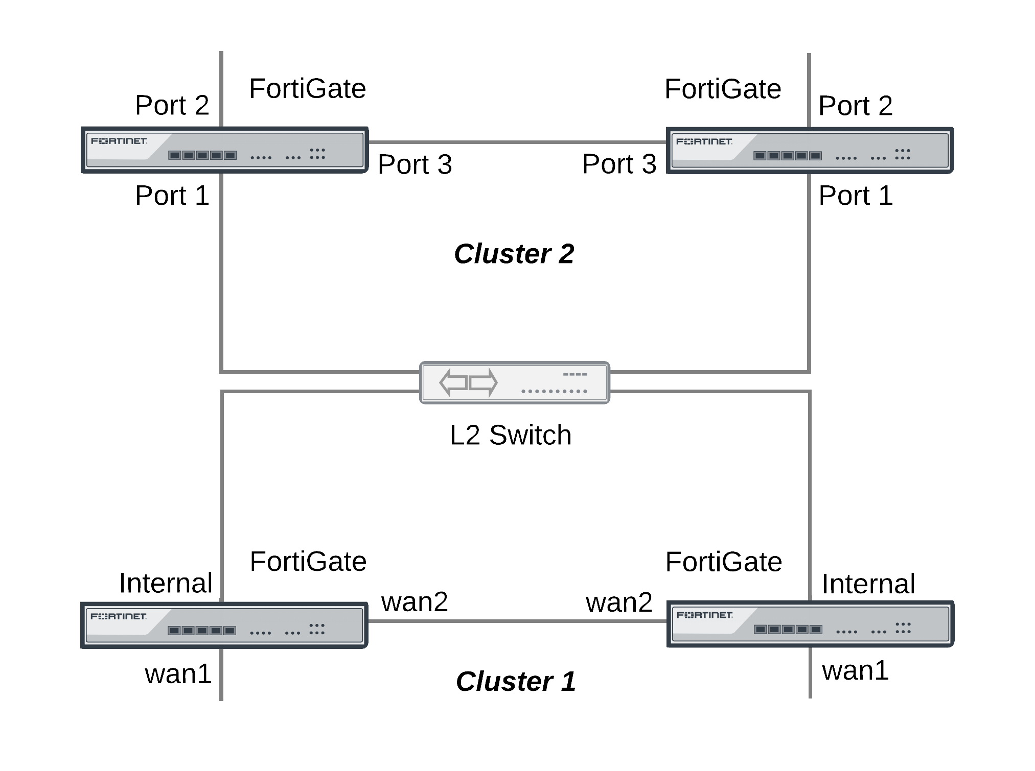
The topology below shows two clusters. The Cluster_1 internal interfaces and the Cluster_2 port 1 interfaces are both connected to the same broadcast domain. In this topology the broadcast domain could be an internal network. Both clusters could also be connected to the Internet or to different networks.
Example HA topology with possible MAC address conflicts
Ping testing for packet loss
If the network is experiencing packet loss, it is possible that you will not notice a problem unless you are constantly pinging both HA clusters. During normal operation of the network you also might not notice packet loss because the loss rate may not be severe enough to timeout TCP sessions. Also many common types if TCP traffic, such as web browsing, may not be greatly affected by packet loss. However, packet loss can have a significant effect on real time protocols that deliver audio and video data.
To test for packet loss you can set up two constant ping sessions, one to each cluster. If packet loss is occurring the two ping sessions should show alternating replies and timeouts from each cluster.
| Cluster_1 | Cluster_2 |
|---|---|
reply
|
timeout
|
reply
|
timeout
|
reply
|
timeout
|
timeout
|
reply
|
timeout
|
reply
|
reply
|
timeout
|
reply
|
timeout
|
timeout
|
reply
|
timeout
|
reply
|
timeout
|
reply
|
timeout
|
reply
|
Viewing MAC address conflicts on attached switches
If two HA clusters with the same virtual MAC address are connected to the same broadcast domain (L2 switch or hub), the MAC address will conflict and bounce between the two clusters. This example Cisco switch MAC address table shows the MAC address flapping between different interfaces (1/0/1 and 1/0/4).
1 0009.0f09.0002 DYNAMIC Gi1/0/1
1 0009.0f09.0002 DYNAMIC Gi1/0/4
Synchronizing the configuration
The FGCP uses a combination of incremental and periodic synchronization to make sure that the configuration of all cluster units is synchronized to that of the primary unit.
The following settings are not synchronized between cluster units:
- HA override.
- HA device priority.
- The virtual cluster priority.
- The FortiGate unit host name.
- The HA priority setting for a ping server (or dead gateway detection) configuration.
- The system interface settings of the HA reserved management interface.
- The HA default route for the reserved management interface, set using the
ha-mgmt-interface-gatewayoption of theconfig system hacommand.
The primary unit synchronizes all other configuration settings, including the other HA configuration settings.
Disabling automatic configuration synchronization
In some cases you may want to use the following command to disable automatic synchronization of the primary unit configuration to all cluster units.
config system ha
set sync-config disable
end
When this option is disabled the cluster no longer synchronizes configuration changes. If a device failure occurs, the new primary unit may not have the same configuration as the failed primary unit. As a result, the new primary unit may process sessions differently or may not function on the network in the same way.
In most cases you should not disable automatic configuration synchronization. However, if you have disabled this feature you can use the execute ha synchronize command to manually synchronize a subordinate unit’s configuration to that of the primary unit.
You must enter execute ha synchronize commands from the subordinate unit that you want to synchronize with the primary unit. Use the execute ha manage command to access a subordinate unit CLI.
For example, to access the first subordinate unit and force a synchronization at any time, even if automatic synchronization is disabled enter:
execute ha manage 0
execute ha synchronize start
You can use the following command to stop a synchronization that is in progress.
execute ha synchronize stop
Incremental synchronization
When you log into the cluster web-based manager or CLI to make configuration changes, you are actually logging into the primary unit. All of your configuration changes are first made to the primary unit. Incremental synchronization then immediately synchronizes these changes to all of the subordinate units.
When you log into a subordinate unit CLI (for example using execute ha manage) all of the configuration changes that you make to the subordinate unit are also immediately synchronized to all cluster units, including the primary unit, using the same process.
Incremental synchronization also synchronizes other dynamic configuration information such as the DHCP server address lease database, routing table updates, IPsec SAs, MAC address tables, and so on. SeeAn introduction to the FGCP for more information about DHCP server address lease synchronization and Synchronizing kernel routing tables for information about routing table updates.
Whenever a change is made to a cluster unit configuration, incremental synchronization sends the same configuration change to all other cluster units over the HA heartbeat link. An HA synchronization process running on the each cluster unit receives the configuration change and applies it to the cluster unit. The HA synchronization process makes the configuration change by entering a CLI command that appears to be entered by the administrator who made the configuration change in the first place.
Synchronization takes place silently, and no log messages are recorded about the synchronization activity. However, log messages can be recorded by the cluster units when the synchronization process enters CLI commands. You can see these log messages on the subordinate units if you enable event logging and set the minimum severity level to Information and then check the event log messages written by the cluster units when you make a configuration change.
You can also see these log messages on the primary unit if you make configuration changes from a subordinate unit.
Periodic synchronization
Incremental synchronization makes sure that as an administrator makes configuration changes, the configurations of all cluster units remain the same. However, a number of factors could cause one or more cluster units to go out of sync with the primary unit. For example, if you add a new unit to a functioning cluster, the configuration of this new unit will not match the configuration of the other cluster units. Its not practical to use incremental synchronization to change the configuration of the new unit.
Periodic synchronization is a mechanism that looks for synchronization problems and fixes them. Every minute the cluster compares the configuration file checksum of the primary unit with the configuration file checksums of each of the subordinate units. If all subordinate unit checksums are the same as the primary unit checksum, all cluster units are considered synchronized.
If one or more of the subordinate unit checksums is not the same as the primary unit checksum, the subordinate unit configuration is considered out of sync with the primary unit. The checksum of the out of sync subordinate unit is checked again every 15 seconds. This re-checking occurs in case the configurations are out of sync because an incremental configuration sequence has not completed. If the checksums do not match after 5 checks the subordinate unit that is out of sync retrieves the configuration from the primary unit. The subordinate unit then reloads its configuration and resumes operating as a subordinate unit with the same configuration as the primary unit.
The configuration of the subordinate unit is reset in this way because when a subordinate unit configuration gets out of sync with the primary unit configuration there is no efficient way to determine what the configuration differences are and to correct them. Resetting the subordinate unit configuration becomes the most efficient way to resynchronize the subordinate unit.
Synchronization requires that all cluster units run the same FortiOS firmware build. If some cluster units are running different firmware builds, then unstable cluster operation may occur and the cluster units may not be able to synchronize correctly.
|
|
Re-installing the firmware build running on the primary unit forces the primary unit to upgrade all cluster units to the same firmware build. |
Console messages when configuration synchronization succeeds
When a cluster first forms, or when a new unit is added to a cluster as a subordinate unit, the following messages appear on the CLI console to indicate that the unit joined the cluster and had its configuring synchronized with the primary unit.
slave's configuration is not in sync with master's, sequence:0
slave's configuration is not in sync with master's, sequence:1
slave's configuration is not in sync with master's, sequence:2
slave's configuration is not in sync with master's, sequence:3
slave's configuration is not in sync with master's, sequence:4
slave starts to sync with master
logout all admin users
slave succeeded to sync with master
Console messages when configuration synchronization fails
If you connect to the console of a subordinate unit that is out of synchronization with the primary unit, messages similar to the following are displayed.
slave is not in sync with master, sequence:0. (type 0x3)
slave is not in sync with master, sequence:1. (type 0x3)
slave is not in sync with master, sequence:2. (type 0x3)
slave is not in sync with master, sequence:3. (type 0x3)
slave is not in sync with master, sequence:4. (type 0x3)
global compared not matched
If synchronization problems occur the console message sequence may be repeated over and over again. The messages all include a type value (in the example type 0x3). The type value can help Fortinet Support diagnose the synchronization problem.
HA out of sync object messages and the configuration objects that they reference
| Out of Sync Message | Configuration Object |
|---|---|
HA_SYNC_SETTING_CONFIGURATION = 0x03
|
/data/config
|
HA_SYNC_SETTING_AV = 0x10
|
|
HA_SYNC_SETTING_VIR_DB = 0x11
|
/etc/vir
|
HA_SYNC_SETTING_SHARED_LIB = 0x12
|
/data/lib/libav.so
|
HA_SYNC_SETTING_SCAN_UNIT = 0x13
|
/bin/scanunitd
|
HA_SYNC_SETTING_IMAP_PRXY = 0x14
|
/bin/imapd
|
HA_SYNC_SETTING_SMTP_PRXY = 0x15
|
/bin/smtp
|
HA_SYNC_SETTING_POP3_PRXY = 0x16
|
/bin/pop3
|
HA_SYNC_SETTING_HTTP_PRXY = 0x17
|
/bin/thttp
|
HA_SYNC_SETTING_FTP_PRXY = 0x18
|
/bin/ftpd
|
HA_SYNC_SETTING_FCNI = 0x19
|
/etc/fcni.dat
|
HA_SYNC_SETTING_FDNI = 0x1a
|
/etc/fdnservers.dat
|
HA_SYNC_SETTING_FSCI = 0x1b
|
/etc/sci.dat
|
HA_SYNC_SETTING_FSAE = 0x1c
|
/etc/fsae_adgrp.cache
|
HA_SYNC_SETTING_IDS = 0x20
|
/etc/ids.rules
|
HA_SYNC_SETTING_IDSUSER_RULES = 0x21
|
/etc/idsuser.rules
|
HA_SYNC_SETTING_IDSCUSTOM = 0x22
|
|
HA_SYNC_SETTING_IDS_MONITOR = 0x23
|
/bin/ipsmonitor
|
HA_SYNC_SETTING_IDS_SENSOR = 0x24
|
/bin/ipsengine
|
HA_SYNC_SETTING_NIDS_LIB = 0x25
|
/data/lib/libips.so
|
HA_SYNC_SETTING_WEBLISTS = 0x30
|
|
HA_SYNC_SETTING_CONTENTFILTER = 0x31
|
/data/cmdb/webfilter.bword
|
HA_SYNC_SETTING_URLFILTER = 0x32
|
/data/cmdb/webfilter.urlfilter
|
HA_SYNC_SETTING_FTGD_OVRD = 0x33
|
/data/cmdb/webfilter.fgtd-ovrd
|
HA_SYNC_SETTING_FTGD_LRATING = 0x34
|
/data/cmdb/webfilter.fgtd-ovrd
|
HA_SYNC_SETTING_EMAILLISTS = 0x40
|
|
HA_SYNC_SETTING_EMAILCONTENT = 0x41
|
/data/cmdb/spamfilter.bword
|
HA_SYNC_SETTING_EMAILBWLIST = 0x42
|
/data/cmdb/spamfilter.emailbwl
|
HA_SYNC_SETTING_IPBWL = 0x43
|
/data/cmdb/spamfilter.ipbwl
|
HA_SYNC_SETTING_MHEADER = 0x44
|
/data/cmdb/spamfilter.mheader
|
HA_SYNC_SETTING_RBL = 0x45
|
/data/cmdb/spamfilter.rbl
|
HA_SYNC_SETTING_CERT_CONF = 0x50
|
/etc/cert/cert.conf
|
HA_SYNC_SETTING_CERT_CA = 0x51
|
/etc/cert/ca
|
HA_SYNC_SETTING_CERT_LOCAL = 0x52
|
/etc/cert/local
|
HA_SYNC_SETTING_CERT_CRL = 0x53
|
/etc/cert/crl
|
HA_SYNC_SETTING_DB_VER = 0x55
|
|
HA_GET_DETAIL_CSUM = 0x71
|
|
HA_SYNC_CC_SIG = 0x75
|
/etc/cc_sig.dat
|
HA_SYNC_CC_OP = 0x76
|
/etc/cc_op
|
HA_SYNC_CC_MAIN = 0x77
|
/etc/cc_main
|
HA_SYNC_FTGD_CAT_LIST = 0x7a
|
/migadmin/webfilter/ublock/ftgd/ data/
|
Comparing checksums of cluster units
You can use the diagnose sys ha showcsum command to compare the configuration checksums of all cluster units. The output of this command shows checksums labelled global and all as well as checksums for each of the VDOMs including the root VDOM. The get system ha-nonsync-csum command can be used to display similar information; however, this command is intended to be used by FortiManager.
The primary unit and subordinate unit checksums should be the same. If they are not you can use the execute ha synchronize command to force a synchronization.
The following command output is for the primary unit of a cluster that does not have multiple VDOMs enabled:
diagnose sys ha showcsum
is_manage_master()=1, is_root_master()=1
debugzone
global: a0 7f a7 ff ac 00 d5 b6 82 37 cc 13 3e 0b 9b 77
root: 43 72 47 68 7b da 81 17 c8 f5 10 dd fd 6b e9 57
all: c5 90 ed 22 24 3e 96 06 44 35 b6 63 7c 84 88 d5
checksum
global: a0 7f a7 ff ac 00 d5 b6 82 37 cc 13 3e 0b 9b 77
root: 43 72 47 68 7b da 81 17 c8 f5 10 dd fd 6b e9 57
all: c5 90 ed 22 24 3e 96 06 44 35 b6 63 7c 84 88 d5
The following command output is for a subordinate unit of the same cluster:
diagnose sys ha showcsum
is_manage_master()=0, is_root_master()=0
debugzone
global: a0 7f a7 ff ac 00 d5 b6 82 37 cc 13 3e 0b 9b 77
root: 43 72 47 68 7b da 81 17 c8 f5 10 dd fd 6b e9 57
all: c5 90 ed 22 24 3e 96 06 44 35 b6 63 7c 84 88 d5
checksum
global: a0 7f a7 ff ac 00 d5 b6 82 37 cc 13 3e 0b 9b 77
root: 43 72 47 68 7b da 81 17 c8 f5 10 dd fd 6b e9 57
all: c5 90 ed 22 24 3e 96 06 44 35 b6 63 7c 84 88 d5
The following example shows using this command for the primary unit of a cluster with multiple VDOMs. Two VDOMs have been added named test and Eng_vdm.
From the primary unit:
config global
sys ha showcsum
is_manage_master()=1, is_root_master()=1
debugzone
global: 65 75 88 97 2d 58 1b bf 38 d3 3d 52 5b 0e 30 a9
test: a5 16 34 8c 7a 46 d6 a4 1e 1f c8 64 ec 1b 53 fe
root: 3c 12 45 98 69 f2 d8 08 24 cf 02 ea 71 57 a7 01
Eng_vdm: 64 51 7c 58 97 79 b1 b3 b3 ed 5c ec cd 07 74 09
all: 30 68 77 82 a1 5d 13 99 d1 42 a3 2f 9f b9 15 53
checksum
global: 65 75 88 97 2d 58 1b bf 38 d3 3d 52 5b 0e 30 a9
test: a5 16 34 8c 7a 46 d6 a4 1e 1f c8 64 ec 1b 53 fe
root: 3c 12 45 98 69 f2 d8 08 24 cf 02 ea 71 57 a7 01
Eng_vdm: 64 51 7c 58 97 79 b1 b3 b3 ed 5c ec cd 07 74 09
all: 30 68 77 82 a1 5d 13 99 d1 42 a3 2f 9f b9 15 53
From the subordinate unit:
config global
diagnose sys ha showcsum
is_manage_master()=0, is_root_master()=0
debugzone
global: 65 75 88 97 2d 58 1b bf 38 d3 3d 52 5b 0e 30 a9
test: a5 16 34 8c 7a 46 d6 a4 1e 1f c8 64 ec 1b 53 fe
root: 3c 12 45 98 69 f2 d8 08 24 cf 02 ea 71 57 a7 01
Eng_vdm: 64 51 7c 58 97 79 b1 b3 b3 ed 5c ec cd 07 74 09
all: 30 68 77 82 a1 5d 13 99 d1 42 a3 2f 9f b9 15 53
checksum
global: 65 75 88 97 2d 58 1b bf 38 d3 3d 52 5b 0e 30 a9
test: a5 16 34 8c 7a 46 d6 a4 1e 1f c8 64 ec 1b 53 fe
root: 3c 12 45 98 69 f2 d8 08 24 cf 02 ea 71 57 a7 01
Eng_vdm: 64 51 7c 58 97 79 b1 b3 b3 ed 5c ec cd 07 74 09
all: 30 68 77 82 a1 5d 13 99 d1 42 a3 2f 9f b9 15 53
How to diagnose HA out of sync messages
This section describes how to use the commands diagnose sys ha showcsum and diagnose debug to diagnose the cause of HA out of sync messages.
If HA synchronization is not successful, use the following procedures on each cluster unit to find the cause.
To determine why HA synchronization does not occur
- Connect to each cluster unit CLI by connected to the console port.
- Enter the following commands to enable debugging and display HA out of sync messages.
diagnose debug enable
diagnose debug console timestamp enable
diagnose debug application hatalk -1
diagnose debug application hasync -1
Collect the console output and compare the out of sync messages with the information on page 203.
- Enter the following commands to turn off debugging.
diagnose debug disable
diagnose debug reset
To determine what part of the configuration is causing the problem
If the previous procedure displays messages that include sync object 0x30 (for example, HA_SYNC_SETTING_CONFIGURATION = 0x03) there is a synchronization problem with the configuration. Use the following steps to determine the part of the configuration that is causing the problem.
If your cluster consists of two cluster units, use this procedure to capture the configuration checksums for each unit. If your cluster consists of more that two cluster units, repeat this procedure for all cluster units that returned messages that include 0x30 sync object messages.
- Connect to each cluster unit CLI by connected to the console port.
- Enter the following command to turn on terminal capture
diagnose debug enable
- Enter the following command to stop HA synchronization.
execute ha sync stop
- Enter the following command to display configuration checksums.
diagnose sys ha showcsum 1
- Copy the output to a text file.
- Repeat for all affected units.
- Compare the text file from the primary unit with the text file from each cluster unit to find the checksums that do not match.
You can use a diff function to compare text files.
- Repeat steps 4 to 7 for each checksum level:
diagnose sys ha showcsum 2
diagnose sys ha showcsum 3
diagnose sys ha showcsum 4
diagnose sys ha showcsum 5
diagnose sys ha showcsum 6
diagnose sys ha showcsum 7
diagnose sys ha showcsum 8
- When the non-matching checksum is found, attempt to drill down further. This is possible for objects that have sub-components.
For example you can enter the following commands:
diagnose sys ha showcsum system.global
diagnose sys ha showcsum system.interface
Generally it is the first non-matching checksum in one of the levels that is the cause of the synchronization problem.
- Attempt to can remove/change the part of the configuration that is causing the problem. You can do this by making configuration changes from the primary unit or subordinate unit CLI.
- Enter the following commands to start HA configuration and stop debugging:
execute ha sync start
diagnose debug disable
diagnose debug reset
Recalculating the checksums to resolve out of sync messages
Sometimes an error can occur when checksums are being calculated by the cluster. As a result of this calculation error the CLI console could display out of sync error messages even though the cluster is otherwise operating normally. You can also sometimes see checksum calculation errors in diagnose sys ha showcsum command output when the checksums listed in the debugzone output don’t match the checksums in the checksum part of the output.
One solution to this problem could be to re-calculate the checksums. The re-calculated checksums should match and the out of sync error messages should stop appearing.
You can use the following command to re-calculate HA checksums:
diagnose sys ha csum-recalculate [<vdom-name> | global]
Just entering the command without options recalculates all checksums. You can specify a VDOM name to just recalculate the checksums for that VDOM. You can also enter global to recalculate the global checksum.
Synchronizing kernel routing tables
In a functioning cluster, the primary unit keeps all subordinate unit kernel routing tables (also called the forwarding information base FIB) up to date and synchronized with the primary unit. After a failover, because of these routing table updates the new primary unit does not have to populate its kernel routing table before being able to route traffic. This gives the new primary unit time to rebuild its regular routing table after a failover.
Use the following command to view the regular routing table. This table contains all of the configured routes and routes acquired from dynamic routing protocols and so on. This routing table is not synchronized. On subordinate units this command will not produce the same output as on the primary unit.
get router info routing-table
Use the following command to view the kernel routing table (FIB). This is the list of resolved routes actually being used by the FortiOS kernel. The output of this command should be the same on the primary unit and the subordinate units.
get router info kernel
This section describes how clusters handle dynamic routing failover and also describes how to use CLI commands to control the timing of routing table updates of the subordinate unit routing tables from the primary unit.
Controlling how the FGCP synchronizes kernel routing table updates
You can use the following commands to control some of the timing settings that the FGCP uses when synchronizing routing updates from the primary unit to subordinate units and maintaining routes on the primary unit after a failover.
config system ha
set route-hold <hold_integer>
set route-ttl <ttl_integer>
set route-wait <wait_integer>
end
Change how long routes stay in a cluster unit routing table
Change the route-ttl time to control how long routes remain in a cluster unit routing table. The time to live range is 5 to 3600 seconds. The default time to live is 10 seconds.
The time to live controls how long routes remain active in a cluster unit routing table after the cluster unit becomes a primary unit. To maintain communication sessions after a cluster unit becomes a primary unit, routes remain active in the routing table for the route time to live while the new primary unit acquires new routes.
By default, route-ttl is set to 10 which may mean that only a few routes will remain in the routing table after a failover. Normally keeping route-ttl to 10 or reducing the value to 5 is acceptable because acquiring new routes usually occurs very quickly, especially if graceful restart is enabled, so only a minor delay is caused by acquiring new routes.
If the primary unit needs to acquire a very large number of routes, or if for other reasons, there is a delay in acquiring all routes, the primary unit may not be able to maintain all communication sessions.
You can increase the route time to live if you find that communication sessions are lost after a failover so that the primary unit can use synchronized routes that are already in the routing table, instead of waiting to acquire new routes.
Change the time between routing updates
Change the route-hold time to change the time that the primary unit waits between sending routing table updates to subordinate units. The route hold range is 0 to 3600 seconds. The default route hold time is 10 seconds.
To avoid flooding routing table updates to subordinate units, set route-hold to a relatively long time to prevent subsequent updates from occurring too quickly. Flooding routing table updates can affect cluster performance if a great deal of routing information is synchronized between cluster units. Increasing the time between updates means that this data exchange will not have to happen so often.
The route-hold time should be coordinated with the route-wait time.
Change the time the primary unit waits after receiving a routing update
Change the route-wait time to change how long the primary unit waits after receiving routing updates before sending the updates to the subordinate units. For quick routing table updates to occur, set route-wait to a relatively short time so that the primary unit does not hold routing table changes for too long before updating the subordinate units.
The route-wait range is 0 to 3600 seconds. The default route-wait is 0 seconds.
Normally, because the route-wait time is 0 seconds the primary unit sends routing table updates to the subordinate units every time its routing table changes.
Once a routing table update is sent, the primary unit waits the route-hold time before sending the next update.
Usually routing table updates are periodic and sporadic. Subordinate units should receive these changes as soon as possible so route-wait is set to 0 seconds. route-hold can be set to a relatively long time because normally the next route update would not occur for a while.
In some cases, routing table updates can occur in bursts. A large burst of routing table updates can occur if a router or a link on a network fails or changes. When a burst of routing table updates occurs, there is a potential that the primary unit could flood the subordinate units with routing table updates. Flooding routing table updates can affect cluster performance if a great deal of routing information is synchronized between cluster units. Setting route-wait to a longer time reduces the frequency of additional updates are and prevents flooding of routing table updates from occurring.
Configuring graceful restart for dynamic routing failover
When an HA failover occurs, neighbor routers will detect that the cluster has failed and remove it from the network until the routing topology stabilizes. During that time the routers may stop sending IP packets to the cluster and communication sessions that would normally be processed by the cluster may time out or be dropped. Also the new primary unit will not receive routing updates and so will not be able to build and maintain its routing database.
You can solve this problem by configuring graceful restart for the dynamic routing protocols that you are using. This section describes configuring graceful restart for OSPF and BGP.
To support graceful restart you should make sure the new primary unit keeps its synchronized routing data long enough to acquire new routing data. You should also increase the HA route time to live, route wait, and route hold values to 60 using the following CLI command:
config system ha
set route-ttl 60
set route-wait 60
set route-hold 60
end
Graceful OSPF restart
You can configure graceful restart (also called nonstop forwarding (NSF)) as described in RFC3623 (Graceful OSPF Restart) to solve the problem of dynamic routing failover. If graceful restart is enabled on neighbor routers, they will keep sending packets to the cluster following the HA failover instead of removing it from the network. The neighboring routers assume that the cluster is experiencing a graceful restart.
After the failover, the new primary unit can continue to process communication sessions using the synchronized routing data received from the failed primary unit before the failover. This gives the new primary unit time to update its routing table after the failover.
You can use the following commands to enable graceful restart or NSF on Cisco routers:
router ospf 1
log-adjacency-changes
nsf ietf helper strict-lsa-checking
If the cluster is running OSPF, use the following command to enable graceful restart for OSFP:
config router ospf
set restart-mode graceful-restart
end
Graceful BGP restart
If the cluster is running BGP only the primary unit keeps BGP peering connections. When a failover occurs, the BGP peering needs to be reestablished. This will happen if you enable BGP graceful restart which causes the adjacent routers to keep the routes active while the BGP peering is restarted by the new primary unit.
|
|
Enabling BGP graceful restart causes the FortiGate's BGP process to restart which can temporarily disrupt traffic through the cluster. So normally you should wait for a quiet time or a maintenance period to enable BGP graceful restart. |
Use the following command to enable graceful restart for BGP and set some graceful restart options.
config router bgp
set graceful-restart enable
set graceful-restart-time 120
set graceful-stalepath-time 360
set graceful-update-delay 120
end
Notifing BGP neighbors when graceful restart is enabled
You can add BGP neighbors and configure the cluster unit to notify these neighbors that it supports graceful restart.
config router bgp
config neighbor
edit <neighbor_address_Ipv4>
set capability-graceful-restart enable
end
end
Bidirectional Forwarding Detection (BFD) enabled BGP graceful restart
You can add a BFD enabled BGP neighbor as a static BFD neighbor using the following command. This example shows how to add a BFD neighbor with IP address 172.20.121.23 that is on the network connected to port4:
config router bfd
config neighbor
edit 172.20.121.23
set port4
end
end
The FGCP supports graceful restart of BFD enabled BGP neighbors. The config router bfd command is needed as the BGP auto-start timer is 5 seconds. After HA failover, BGP on the new primary unit has to wait for 5 seconds to connect to its neighbors, and then register BFD requests after establishing the connections. With static BFD neighbors, BFD requests and sessions can be created as soon as possible after the failover. The new command get router info bfd requests shows the BFD peer requests.
A BFD session created for a static BFD neighbor/peer request will initialize its state as "INIT" instead of "DOWN" and its detection time asbfd-required-min-rx * bfd-detect-mult milliseconds.
When a BFD control packet with nonzero your_discr is received, if no session can be found to match the your_discr, instead of discarding the packet, other fields in the packet, such as addressing information, are used to choose one session that was just initialized, with zero as its remote discriminator.
When a BFD session in the up state receives a control packet with zero as your_discr and down as the state, the session will change its state into down but will not notify this down event to BGP and/or other registered clients.
Synchronizing IPsec VPN SAs
The FGCP synchronizes IPsec security associations (SAs) between cluster members so that if a failover occurs, the cluster can resume IPsec sessions without having to establish new SAs. The result is improved failover performance because IPsec sessions are not interrupted to establish new SAs. Also, establishing a large number of SAs can reduce cluster performance.
The FGCP implements slightly different synchronization mechanisms for IKEv1 and IKEv2.
Synchronizing SAs for IKEv1
When an SA is synchronized to the subordinate units. the sequence number is set to the maximum sequence number. After a failover, all inbound traffic that connects with the new primary unit and uses the SA will be accepted without needing to re-key. However, first outbound packet to use the SA causes the sequence number to overflow and so causes the new primary unit to re-key the SA.
Please note the following:
- The cluster synchronizes all IPsec SAs.
- IPsec SAs are not synchronized until the IKE process has finished synchronizing the ISAKMP SAs. This is required in for dialup tunnels since it is the synchronizing of the ISAKMP SA that creates the dialup tunnel.
- A dialup interface is created as soon as the phase1 is complete. This ensures that the when HA synchronizes phase1 information the dialup name is included.
- If the IKE process re-starts for any reason it deletes any dialup tunnels that exist. This forces the peer to re-key them.
- IPsec SA deletion happens immediately. Routes associated with a dialup tunnel that is being deleted are cleaned up synchronously as part of the delete, rather than waiting for the SA hard-expiry.
- The FGCP does not sync the IPsec tunnel MTU from the primary unit to the subordinate units. This means that after HA failover if the first packet received by the FortiGate unit arrives after the HA route has been deleted and before the new route is added and the packet is larger than the default MTU of 1024 then the FortiGate unit sends back an ICMP fragmentation required. However, as soon as routing is re-established then the MTU will be corrected and traffic will flow.
Synchronizing SAs for IKEv2
Due to the way the IKEv2 protocol is designed the FGCP cannot use exactly the same solution that is used for synchronizing IKEv1 SAs, though it is similar.
For IKEv2, like IKEv1, the FGCP synchronizes IKE and ISAKMP SAs from the primary unit to the subordinate units. However, for IKEv2 the FGCP cannot actually use this IKE SA to send/receive IKE traffic because IKEv2 includes a sequence number in every IKE message and thus it would require synchronizing every message to the subordinate units to keep the sequence numbers on the subordinate units up to date.
Instead, the FGCP synchronizes IKEv2 Message IDs. This Message ID Sync allows IKEv2 to re-negotiate send and receive message ID counters after a failover. By doing this, the established IKE SA can remain up, instead of re-negotiating.
The diagnose vpn ike stats command shows statistics for the number of HA messages sent/received for IKEv2. The output of this command includes a number of fields prefixed with ha that contain high availably related-data. For example:
.
.
.
ha.resync: 0
ha.vike.sync: 0
ha.conn.sync: 0
ha.sync.tx: 1
ha.sync.rx: 0
ha.sync.rx.len.bad: 0
.
.
.
Link failover (port monitoring or interface monitoring)
Link failover means that if a monitored interface fails, the cluster reorganizes to reestablish a link to the network that the monitored interface was connected to and to continue operating with minimal or no disruption of network traffic.
You configure monitored interfaces (also called interface monitoring or port monitoring) by selecting the interfaces to monitor as part of the cluster HA configuration.
You can monitor up to 64 interfaces.
The interfaces that you can monitor appear on the port monitor list. You can monitor all FortiGate interfaces including redundant interfaces and 802.3ad aggregate interfaces.
You cannot monitor the following types of interfaces (you cannot select the interfaces on the port monitor list):
- FortiGate interfaces that contain an internal switch.
- VLAN subinterfaces.
- IPsec VPN interfaces.
- Individual physical interfaces that have been added to a redundant or 802.3ad aggregate interface.
- FortiGate-5000 series backplane interfaces that have not been configured as network interfaces.
If you are configuring a virtual cluster you can create a different port monitor configuration for each virtual cluster. Usually for each virtual cluster you would monitor the interfaces that have been added to the virtual domains in each virtual cluster.
|
|
Wait until after the cluster is up and running to enable interface monitoring. You do not need to configure interface monitoring to get a cluster up and running and interface monitoring will cause failovers if for some reason during initial setup a monitored interface has become disconnected. You can always enable interface monitoring once you have verified that the cluster is connected and operating properly. |
|
|
You should only monitor interfaces that are connected to networks, because a failover may occur if you monitor an unconnected interface. |
To enable interface monitoring - web-based manager
Use the following steps to monitor the port1 and port2 interfaces of a cluster.
- Connect to the cluster web-based manager.
- Go to System > Config > HA and edit the primary unit (Role is MASTER).
- Select the Port Monitor check boxes for the port1 and port2 interfaces and select OK.
The configuration change is synchronized to all cluster units.
To enable interface monitoring - CLI
Use the following steps to monitor the port1 and port2 interfaces of a cluster.
- Connect to the cluster CLI.
- Enter the following command to enable interface monitoring for port1 and port2.
configure system ha
set monitor port1 port2
end
The following example shows how to enable monitoring for the external, internal, and DMZ interfaces.
config system ha
set monitor external internal dmz
end
With interface monitoring enabled, during cluster operation, the cluster monitors each cluster unit to determine if the monitored interfaces are operating and connected. Each cluster unit can detect a failure of its network interface hardware. Cluster units can also detect if its network interfaces are disconnected from the switch they should be connected to.
|
|
Cluster units cannot determine if the switch that its interfaces are connected to is still connected to the network. However, you can use remote IP monitoring to make sure that the cluster unit can connect to downstream network devices. See Remote link failover. |
Because the primary unit receives all traffic processed by the cluster, a cluster can only process traffic from a network if the primary unit can connect to it. So, if the link between a network and the primary unit fails, to maintain communication with this network, the cluster must select a different primary unit; one that is still connected to the network. Unless another link failure has occurred, the new primary unit will have an active link to the network and will be able to maintain communication with it.
To support link failover, each cluster unit stores link state information for all monitored cluster units in a link state database. All cluster units keep this link state database up to date by sharing link state information with the other cluster units. If one of the monitored interfaces on one of the cluster units becomes disconnected or fails, this information is immediately shared with all cluster units.
If a monitored interface on the primary unit fails
If a monitored interface on the primary unit fails, the cluster renegotiates to select a new primary unit using the process described in An introduction to the FGCP. Because the cluster unit with the failed monitored interface has the lowest monitor priority, a different cluster unit becomes the primary unit. The new primary unit should have fewer link failures.
After the failover, the cluster resumes and maintains communication sessions in the same way as for a device failure. See Device failover.
If a monitored interface on a subordinate unit fails
If a monitored interface on a subordinate unit fails, this information is shared with all cluster units. The cluster does not renegotiate. The subordinate unit with the failed monitored interface continues to function in the cluster.
In an active-passive cluster after a subordinate unit link failover, the subordinate unit continues to function normally as a subordinate unit in the cluster.
In an active-active cluster after a subordinate unit link failure:
- The subordinate unit with the failed monitored interface can continue processing connections between functioning interfaces. However, the primary unit stops sending sessions to a subordinate unit that use any failed monitored interfaces on the subordinate unit.
- If session pickup is enabled, all sessions being processed by the subordinate unit failed interface that can be failed over are failed over to other cluster units. Sessions that cannot be failed over are lost and have to be restarted.
- If session pickup is not enabled all sessions being processed by the subordinate unit failed interface are lost.
How link failover maintains traffic flow
Monitoring an interface means that the interface is connected to a high priority network. As a high priority network, the cluster should maintain traffic flow to and from the network, even if a link failure occurs. Because the primary unit receives all traffic processed by the cluster, a cluster can only process traffic from a network if the primary unit can connect to it. So, if the link that the primary unit has to a high priority network fails, to maintain traffic flow to and from this network, the cluster must select a different primary unit. This new primary unit should have an active link to the high priority network.
A link failure causes a cluster to select a new primary unit
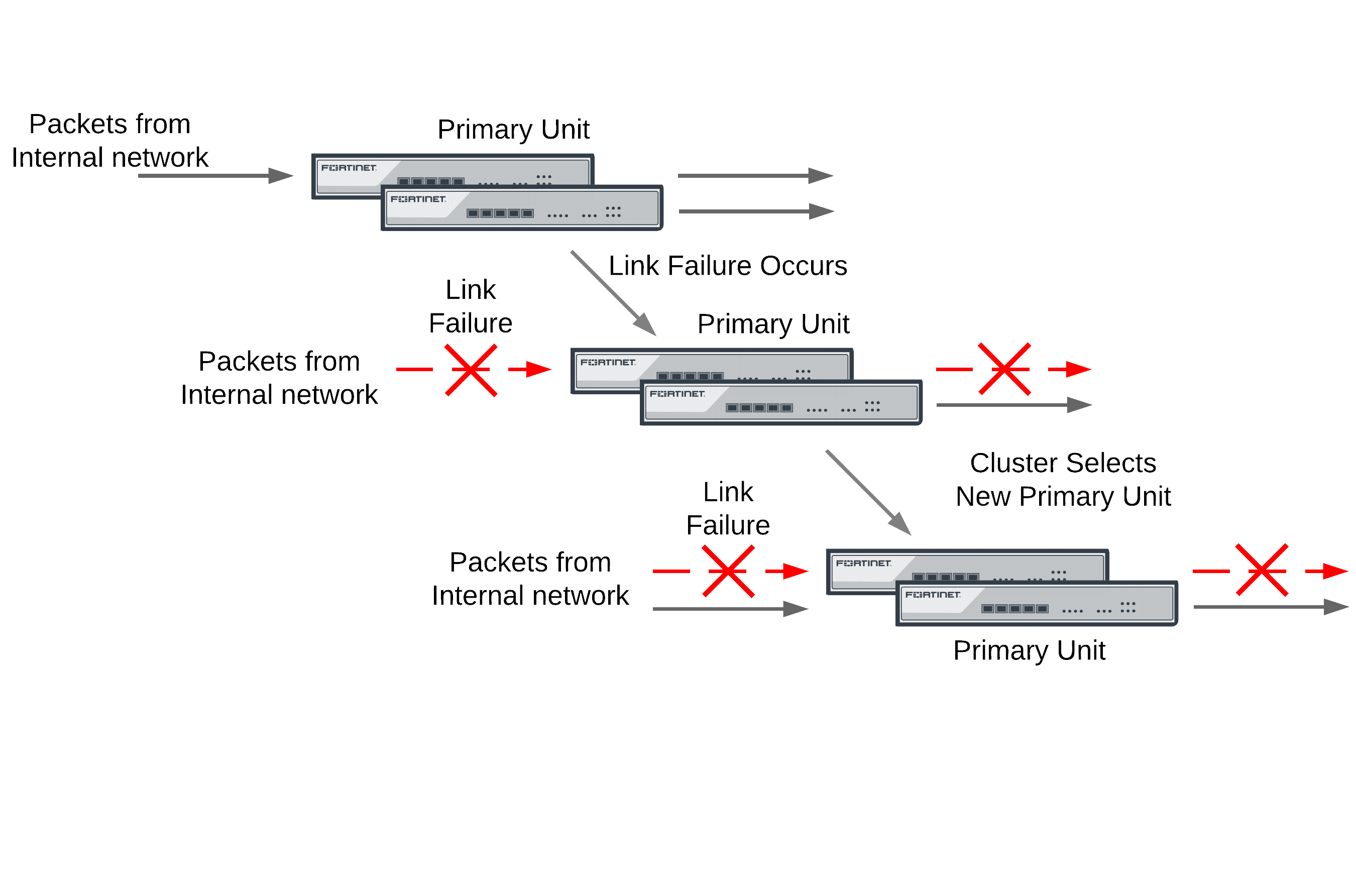
If a monitored interface on the primary unit fails, the cluster renegotiates and selects the cluster unit with the highest monitor priority to become the new primary unit. The cluster unit with the highest monitor priority is the cluster unit with the most monitored interfaces connected to networks.
After a link failover, the primary unit processes all traffic and all subordinate units, even the cluster unit with the link failure, share session and link status. In addition all configuration changes, routes, and IPsec SAs are synchronized to the cluster unit with the link failure.
In an active-active cluster, the primary unit load balances traffic to all the units in the cluster. The cluster unit with the link failure can process connections between its functioning interfaces (for, example if the cluster has connections to an internal, external, and DMZ network, the cluster unit with the link failure can still process connections between the external and DMZ networks).
Recovery after a link failover and controlling primary unit selection (controlling falling back to the prior primary unit)
If you find and correct the problem that caused a link failure (for example, re-connect a disconnected network cable) the cluster updates its link state database and re-negotiates to select a primary unit.
What happens next depends on how the cluster configuration affects primary unit selection:
- The former primary unit will once again become the primary unit (falling back to becoming the primary unit)
- The primary unit will not change.
As described in An introduction to the FGCP, when the link is restored, if no options are configured to control primary unit selection and the cluster age difference is less than 300 seconds the former primary unit will once again become the primary unit. If the age differences are greater than 300 seconds then a new primary unit is not selected. Since you have no control on the age difference the outcome can be unpredictable. This is not a problem in cases where its not important which unit becomes the primary unit.
Preventing a primary unit change after a failed link is restored
Some organizations will not want the cluster to change primary units when the link is restored. Instead they would rather wait to restore the primary unit during a maintenance window. This functionality is not directly supported, but you can experiment with changing some primary unit selection settings. For example, in most cases it should work to enable override on all cluster units and make sure their priorities are the same. This should mean that the primary unit should not change after a failed link is restored.
Then, when you want to restore the original primary unit during a maintenance window you can just set its Device Priority higher. After it becomes the primary unit you can reset all device priorities to the same value. Alternatively during a maintenance window you could reboot the current primary unit and any subordinate units except the one that you want to become the primary unit.
If the override CLI keyword is enabled on one or more cluster units and the device priority of a cluster unit is set higher than the others, when the link failure is repaired and the cluster unit with the highest device priority will always become the primary unit.
Testing link failover
You can test link failure by disconnecting the network cable from a monitored interface of a cluster unit. If you disconnect a cable from a primary unit monitored interface the cluster should renegotiate and select one of the other cluster units as the primary unit. You can also verify that traffic received by the disconnected interface continues to be processed by the cluster after the failover.
If you disconnect a cable from a subordinate unit interface the cluster will not renegotiate.
Updating MAC forwarding tables when a link failover occurs
When a FortiGate HA cluster is operating and a monitored interface fails on the primary unit, the primary unit usually becomes a subordinate unit and another cluster unit becomes the primary unit. After a link failover, the new primary unit sends gratuitous ARP packets to refresh the MAC forwarding tables (also called arp tables) of the switches connected to the cluster. This is normal link failover operation.
Even when gratuitous ARP packets are sent, some switches may not be able to detect that the primary unit has become a subordinate unit and will keep sending packets to the former primary unit. This can occur if the switch does not detect the failure and does not clear its MAC forwarding table.
You have another option available to make sure the switch detects the failover and clears its MAC forwarding tables. You can use the following command to cause a cluster unit with a monitored interface link failure to briefly shut down all of its interfaces (except the heartbeat interfaces) after the failover occurs:
config system ha
set link-failed-signal enable
end
Usually this means each interface of the former primary unit is shut down for about a second. When this happens the switch should be able to detect this failure and clear its MAC forwarding tables of the MAC addresses of the former primary unit and pickup the MAC addresses of the new primary unit. Each interface will shut down for a second but the entire process usually takes a few seconds. The more interfaces the FortiGate unit has, the longer it will take.
Normally, the new primary unit also sends gratuitous ARP packets that also help the switch update its MAC forwarding tables to connect to the new primary unit. If link-failed-signal is enabled, sending gratuitous ARP packets is optional and can be disabled if you don‘t need it or if its causing problems. See Disabling gratuitous ARP packets after a failover.
Multiple link failures
Every time a monitored interface fails, the cluster repeats the processes described above. If multiple monitored interfaces fail on more than one cluster unit, the cluster continues to negotiate to select a primary unit that can provide the most network connections.
Example link failover scenarios
For the following examples, assume a cluster configuration consisting of two FortiGate units (FGT_1 and FGT_2) connected to three networks: internal using port2, external using port1, and DMZ using port3. In the HA configuration, the device priority of FGT_1 is set higher than the unit priority of FGT_2.
The cluster processes traffic flowing between the internal and external networks, between the internal and DMZ networks, and between the external and DMZ networks. If there are no link failures, FGT1 becomes the primary unit because it has the highest device priority.
Sample link failover scenario topology
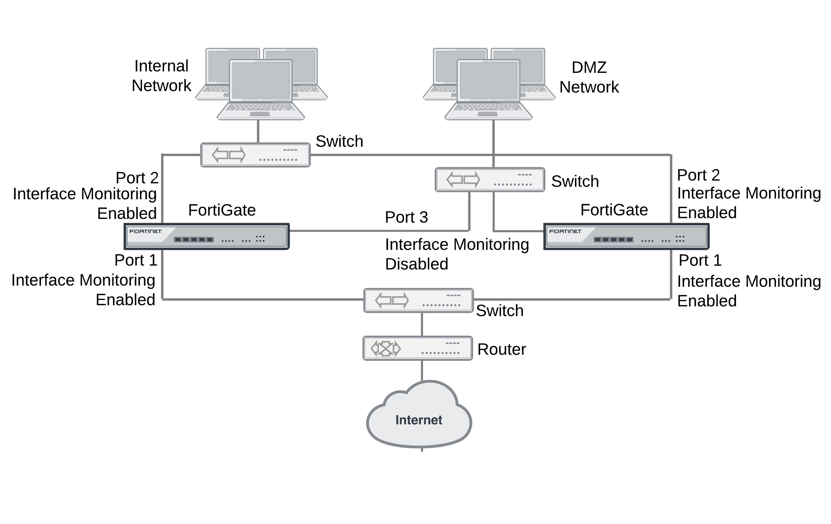
Example the port1 link on FGT_1 fails
If the port1 link on FGT_1 fails, FGT_2 becomes primary unit because it has fewer interfaces with a link failure. If the cluster is operating in active-active mode, the cluster load balances traffic between the internal network (port2) and the DMZ network (port3). Traffic between the Internet (port1) and the internal network (port2) and between the Internet (port1) and the DMZ network (port3) is processed by the primary unit only.
Example port2 on FGT_1 and port1 on FGT_2 fail
If port2 on FGT_1 and port1 on FGT_2 fail, then FGT_1 becomes the primary unit. After both of these link failures, both cluster units have the same monitor priority. So the cluster unit with the highest device priority (FGT_1) becomes the primary unit.
Only traffic between the Internet (port1) and DMZ (port3) networks can pass through the cluster and the traffic is handled by the primary unit only. No load balancing will occur if the cluster is operating in active-active mode.
Subsecond failover
On FortiGate models 395xB and 3x40B HA link failover supports subsecond failover (that is a failover time of less than one second). Subsecond failover is available for interfaces that can issue a link failure system call when the interface goes down. When an interface experiences a link failure and sends the link failure system call, the FGCP receives the system call and initiates a link failover.
For interfaces that do not support subsecond failover, port monitoring regularly polls the connection status of monitored interfaces. When a check finds that an interface has gone down, port monitoring causes a link failover. Subsecond failover results in a link failure being detected sooner because the system doesn’t have to wait for the next poll to find out about the failure.
Subsecond failover can accelerate HA failover to reduce the link failover time to less than one second under ideal conditions. Actual failover performance may be vary depending on traffic patterns and network configuration. For example, some network devices may respond slowly to an HA failover.
No configuration changes are required to support subsecond failover. However, for best subsecond failover results, the recommended heartbeat interval is 100ms and the recommended lost heartbeat threshold is 5 (see Modifying heartbeat timing).
config system ha
set hb-lost-threshold 5
set hb-interval 1
end
For information about how to reduce failover times, see Failover performance.
Remote link failover
Remote link failover (also called remote IP monitoring) is similar to HA port monitoring and link health monitoring (also known as dead gateway detection). Port monitoring causes a cluster to failover if a monitored primary unit interface fails or is disconnected. Remote IP monitoring uses link health monitors configured for FortiGate interfaces on the primary unit to test connectivity with IP addresses of network devices. Usually these would be IP addresses of network devices not directly connected to the cluster. For example, a downstream router. Remote IP monitoring causes a failover if one or more of these remote IP addresses does not respond to link health checking.
By being able to detect failures in network equipment not directly connected to the cluster, remote IP monitoring can be useful in a number of ways depending on your network configuration. For example, in a full mesh HA configuration, with remote IP monitoring, the cluster can detect failures in network equipment that is not directly connected to the cluster but that would interrupt traffic processed by the cluster if the equipment failed.
Example HA remote IP monitoring topology
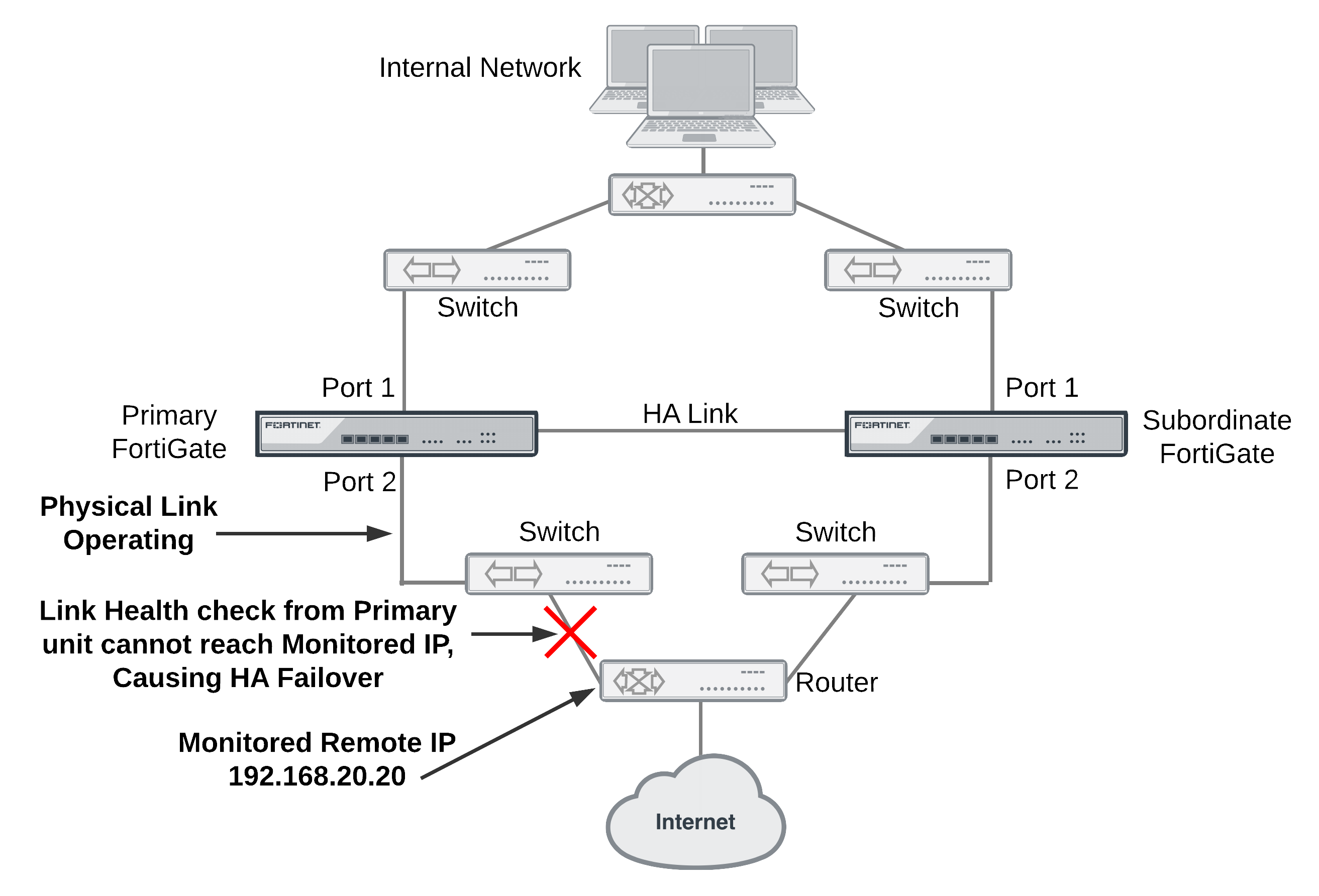
In the simplified example topology shown above, the switch connected directly to the primary unit is operating normally but the link on the other side of the switches fails. As a result traffic can no longer flow between the primary unit and the Internet.
To detect this failure you can create a link health monitor for port2 that causes the primary unit to test connectivity to 192.168.20.20. If the health monitor cannot connect to 192.268.20.20 the cluster to fails over and the subordinate unit becomes the new primary unit. After the failover, the health check monitor on the new primary unit can connect to 192.168.20.20 so the failover maintains connectivity between the internal network and the Internet through the cluster.
To configure remote IP monitoring
- Enter the following commands to configure HA remote monitoring for the example topology.
- Enter the
pingserver-monitor-interfacekeyword to enable HA remote IP monitoring on port2. - Leave the
pingserver-failover-thresholdset to the default value of 5. This means a failover occurs if the link health monitor doesn’t get a response after 5 attempts. - Enter the
pingserver-flip-timeoutkeyword to set the flip timeout to 120 minutes. After a failover, if HA remote IP monitoring on the new primary unit also causes a failover, the flip timeout prevents the failover from occurring until the timer runs out. Setting thepingserver‑flip‑timeoutto 120 means that remote IP monitoring can only cause a failover every 120 minutes. This flip timeout is required to prevent repeating failovers if remote IP monitoring causes a failover from all cluster units because none of the cluster units can connect to the monitored IP addresses.
config system ha
set pingserver-monitor-interface port2
set pingserver-failover-threshold 5
set pingserver-flip-timeout 120
end
- Enter the following commands to add a link health monitor for the port2 interface and to set HA remote IP monitoring priority for this link health monitor.
- Enter the
detectserverkeyword to set the health monitor server IP address to 192.168.20.20. - Leave the
ha-prioritykeyword set to the default value of 1. You only need to change this priority if you change the HApingserver-failover-threshold. Theha-prioritysetting is not synchronized among cluster units.
|
|
The ha-priority setting is not synchronized among cluster units. So if you want to change the ha-priority setting you must change it separately on each cluster unit. Otherwise it will remain set to the default value of 1. |
- Use the
intervalkeyword to set the time between link health checks and use thefailtimekeyword to set the number of times that a health check can fail before a failure is detected (the failover threshold). The following example reduces the failover threshold to 2 but keeps the health check interval at the default value of 5.
config system link-monitor
edit ha-link-monitor
set server 192.168.20.20
set srcintf port2
set ha-priority 1
set interval 5
set failtime 2
end
|
|
You can also do this from the web-based manager by going to Router > Static > Settings > Link Health Monitor, selecting Create New and set Interface to port2, Probe Type to Ping, Server to 192.168.20.20, Probe Interval to 5, Failure Threshold to 2 and HA Priority to 1. |
Adding HA remote IP monitoring to multiple interfaces
You can enable HA remote IP monitoring on multiple interfaces by adding more interface names to the pingserver-monitor-interface keyword. If your FortiGate configuration includes VLAN interfaces, aggregate interfaces and other interface types, you can add the names of these interfaces to the pingserver-monitor-interface keyword to configure HA remote IP monitoring for these interfaces.
For example, enable remote IP monitoring for interfaces named port2, port20, and vlan_234:
config system ha
set pingserver-monitor-interface port2 port20 vlan_234
set pingserver-failover-threshold 10
set pingserver-flip-timeout 120
end
Then configure health monitors for each of these interfaces. In the following example, default values are accepted for all settings other than the server IP address.
config system link-monitor
edit port2
set srcintf port2
set server 192.168.20.20
next
edit port20
set srcintf port20
set server 192.168.20.30
next
edit vlan_234
set srcintf vlan_234
set server 172.20.12.10
end
Changing the link monitor failover threshold
If you have multiple link monitors you may want a failover to occur only if more than one of them fails.
For example, you may have 3 link monitors configured on three interfaces but only want a failover to occur if two of the link monitors fail. To do this you must set the HA priorities of the link monitors and the HA pingserver-failover-threshold so that the priority of one link monitor is less than the failover threshold but the added priorities of two link monitors is equal to or greater than the failover threshold. Failover occurs when the HA priority of all failed link monitors reaches or exceeds the threshold.
For example, set the failover threshold to 10 and monitor three interfaces:
config system ha
set pingserver-monitor-interface port2 port20 vlan_234
set pingserver-failover-threshold 10
set pingserver-flip-timeout 120
end
Then set the HA priority of link monitor server to 5.
|
|
The HA Priority (ha-priority) setting is not synchronized among cluster units. In the following example, you must set the HA priority to 5 by logging into each cluster unit. |
config system link-monitor
edit port2
set server 192.168.20.20
set ha-priority 5
next
edit port20
set server 192.168.20.30
set ha-priority 5
next
edit vlan_234
set server 172.20.12.10
set ha-priority 5
end
If only one of the link monitors fails, the total link monitor HA priority will be 5, which is lower than the failover threshold so a failover will not occur. If a second link monitor fails, the total link monitor HA priority of 10 will equal the failover threshold, causing a failover.
By adding multiple link monitors and setting the HA priorities for each, you can fine tune remote IP monitoring. For example, if it is more important to maintain connections to some networks you can set the HA priorities higher for these link monitors. And if it is less important to maintain connections to other networks you can set the HA priorities lower for these link monitors. You can also adjust the failover threshold so that if the cluster cannot connect to one or two high priority IP addresses a failover occurs. But a failover will not occur if the cluster cannot connect to one or two low priority IP addresses.
Monitoring multiple IP addresses from one interface
You can add multiple IP addresses to a single link monitor to use HA remote IP monitoring to monitor more than one IP address from a single interface. If you add multiple IP addresses, the health checking will be with all of the addresses at the same time. The link monitor only fails when no responses are received from all of the addresses.
config system link-monitor
edit port2
set server 192.168.20.20 192.168.20.30 172.20.12.10
end
Flip timeout
The HA remote IP monitoring configuration also involves setting a flip timeout. The flip timeout is required to reduce the frequency of failovers if, after a failover, HA remote IP monitoring on the new primary unit also causes a failover. This can happen if the new primary unit cannot connect to one or more of the monitored remote IP addresses. The result could be that until you fix the network problem that blocks connections to the remote IP addresses, the cluster will experience repeated failovers. You can control how often the failovers occur by setting the flip timeout. The flip timeout stops HA remote IP monitoring from causing a failover until the primary unit has been operating for the duration of the flip timeout.
If you set the flip timeout to a relatively high number of minutes you can find and repair the network problem that prevented the cluster from connecting to the remote IP address without the cluster experiencing very many failovers. Even if it takes a while to detect the problem, repeated failovers at relatively long time intervals do not usually disrupt network traffic.
Use the following command to set the flip timeout to 3 hours (360 minutes):
config system ha
set pingserver-flip-timeout 360
end
Detecting HA remote IP monitoring failovers
Just as with any HA failover, you can detect HA remote IP monitoring failovers by using SNMP to monitor for HA traps. You can also use alert email to receive notifications of HA status changes and monitor log messages for HA failover log messages. In addition, FortiGate units send the critical log message Ping Server is down when a ping server fails. The log message includes the name of the interface that the ping server has been added to.
Session failover (session pick-up)
Session failover means that a cluster maintains active network TCP and IPsec VPN sessions (including NAT sessions) after a device or link failover. You can also configure session failover to maintain UDP and ICMP sessions. Session failover does not failover multicast, or SSL VPN sessions.
FortiGate HA does not support session failover by default. To enable session failover go to System > Config > HA and select Enable Session Pick-up.
From the CLI enter:
config system ha
set session-pickup enable
end
To support session failover, when Enable Session Pick-up is selected, the FGCP maintains an HA session table for most TCP communication sessions being processed by the cluster and synchronizes this session table with all cluster units. If a cluster unit fails, the HA session table information is available to the remaining cluster units and these cluster units use this session table to resume most of the TCP sessions that were being processed by the failed cluster unit without interruption.
If session pickup is enabled, you can use the following command to also enable UDP and ICMP session failover:
config system ha
set session-pickup-connectionless enable
end
You must enable session pickup for session failover protection. If you do not require session failover protection, leaving session pickup disabled may reduce CPU usage and reduce HA heartbeat network bandwidth usage.
If session pickup is not selected
If Enable Session Pick-up is not selected, the FGCP does not maintain an HA session table and most TCP sessions do not resume after a failover. After a device or link failover all sessions are briefly interrupted and must be re-established at the application level after the cluster renegotiates.
Many protocols can successfully restart sessions with little, if any, loss of data. For example, after a failover, users browsing the web can just refresh their browsers to resume browsing. Since most HTTP sessions are very short, in most cases they will not even notice an interruption unless they are downloading large files. Users downloading a large file may have to restart their download after a failover.
Other protocols may experience data loss and some protocols may require sessions to be manually restarted. For example, a user downloading files with FTP may have to either restart downloads or restart their FTP client.
Some sessions may resume after a failover whether or not enable session pick-up is selected:
- UDP, ICMP, multicast and broadcast packet session failover
- FortiOS Carrier GTP session failover
- Active-active HA subordinate units sessions can resume after a failover
Improving session synchronization performance
Two HA configuration options are available to reduce the performance impact of enabling session pickup. They include reducing the number of sessions that are synchronized by adding a session pickup delay and using more FortiGate interfaces for session synchronization.
Reducing the number of sessions that are synchronized
Enable the session-pickup-delay CLI option to reduce the number of sessions that are synchronized by synchronizing sessions only if they remain active for more than 30 seconds. Enabling this option could greatly reduce the number of sessions that are synchronized if a cluster typically processes very many short duration sessions, which is typical of most HTTP traffic for example.
Use the following command to enable a 30 second session pickup delay:
config system ha
set session-pickup-delay enable
end
Enabling session pickup delay means that if a failover occurs more sessions may not be resumed after a failover. In most cases short duration sessions can be restarted with only a minor traffic interruption. However, if you notice too many sessions not resuming after a failover you might want to disable this setting.
Using multiple FortiGate interfaces for session synchronization
Using the session-sync-dev option you can select one or more FortiGate interfaces to use for synchronizing sessions as required for session pickup. Normally session synchronization occurs over the HA heartbeat link. Using this HA option means only the selected interfaces are used for session synchronization and not the HA heartbeat link. If you select more than one interface, session synchronization traffic is load balanced among the selected interfaces.
Moving session synchronization from the HA heartbeat interface reduces the bandwidth required for HA heartbeat traffic and may improve the efficiency and performance of the cluster, especially if the cluster is synchronizing a large number of sessions. Load balancing session synchronization among multiple interfaces can further improve performance and efficiency if the cluster is synchronizing a large number of sessions.
Use the following command to perform cluster session synchronization using the port10 and port12 interfaces.
config system ha
set session-sync-dev port10 port12
end
Session synchronization packets use Ethertype 0x8892. The interfaces to use for session synchronization must be connected together either directly using the appropriate cable (possible if there are only two units in the cluster) or using switches. If one of the interfaces becomes disconnected the cluster uses the remaining interfaces for session synchronization. If all of the session synchronization interfaces become disconnected, session synchronization reverts back to using the HA heartbeat link. All session synchronization traffic is between the primary unit and each subordinate unit.
Since large amounts of session synchronization traffic can increase network congestion, it is recommended that you keep this traffic off of your network by using dedicated connections for it.
Synchronizing GTP sessions to support GTP tunnel failover
FortiOS Carrier GPRS Tunneling Protocol (GTP) sessions are not normally synchronized by the FGCP, even if you enable session pickup. You can provide GTP session synchronization by using the session-sync-dev command to select one or two session sync interfaces. You must also connect these interfaces together either with direct connections or using switches.
You can also use the command, diagnose firewall gtp hash-stat to display GTP hash stat separately.
Session failover not supported for all sessions
Most of the features applied to sessions by FortiGate security profile functionality require the FortiGate unit to maintain very large amounts of internal state information for each session. The FGCP does not synchronize internal state information for the following security profile features, so the following types of sessions will not resume after a failover:
- Virus scanning of HTTP, HTTPS, FTP, IMAP, IMAPS, POP3, POP3S, SMTP, SMTPS, IM, CIFS, and NNTP sessions,
- Web filtering and FortiGuard Web Filtering of HTTP and HTTPS sessions,
- Spam filtering of IMAP, IMAPS, POP3, POP3S, SMTP, and SMTPS sessions,
- DLP scanning of IMAP, IMAPS, POP3, POP3S, SMTP, SMTPS, SIP, SIMPLE, and SCCP sessions,
- DLP archiving of HTTP, HTTPS, FTP, IMAP, IMAPS, POP3, SMTP, SMTPS, IM, NNTP, AIM, ICQ, MSN, Yahoo! IM, SIP, SIMPLE, and SCCP signal control sessions,
|
|
Active-active clusters can resume some of these sessions after a failover. See Active-active HA subordinate units sessions can resume after a failover for details. |
If you use these features to protect most of the sessions that your cluster processes, enabling session failover may not actually provide significant session failover protection.
TCP sessions that are not being processed by these security profile features resume after a failover even if these sessions are accepted by security policies with security profile options configured. Only TCP sessions that are actually being processed by these security profile features do not resume after a failover. For example:
- TCP sessions that are not virus scanned, web filtered, spam filtered, content archived, or are not SIP, SIMPLE, or SCCP signal traffic resume after a failover, even if they are accepted by a security policy with security profile options enabled. For example, SNMP TCP sessions resume after a failover because FortiOS does not apply any security profile options to SNMP sessions.
- TCP sessions for a protocol for which security profile features have not been enabled resume after a failover even if they are accepted by a security policy with security profile features enabled. For example, if you have not enabled any antivirus or content archiving settings for FTP, FTP sessions resume after a failover.
The following security profile features do not affect TCP session failover:
- IPS does not affect session failover. Sessions being scanned by IPS resume after a failover. After a failover; however, IPS can only perform packet-based inspection of resumed sessions; reducing the number of vulnerabilities that IPS can detect. This limitation only applies to in-progress resumed sessions.
- Application control does not affect session failover. Sessions that are being monitored by application control resume after a failover.
- Logging enabled form security profile features does not affect session failover. security profile logging writes log messages for security profile events; such as when a virus is found by antivirus scanning, when Web Filtering blocks a URL, and so on. Logging does not enable features that would prevent sessions from being failed over, logging just reports on the activities of enabled features.
If more than one security profile feature is applied to a TCP session, that session will not resume after a failover as long as one of the security profile features prevents session failover. For example:
- Sessions being scanned by IPS and also being virus scanned do not resume after a failover.
- Sessions that are being monitored by application control and that are being DLP archived or virus scanned will not resume after a failover.
IPv6, NAT64, and NAT66 session failover
The FGCP supports IPv6, NAT64, and NAT66 session failover, if session pickup is enabled, these sessions are synchronized between cluster members and after an HA failover the sessions will resume with only minimal interruption.
SIP session failover
The FGCP supports SIP session failover (also called stateful failover) for active‑passive HA. To support SIP session failover, create a standard HA configuration and select Enable Session Pick-up option.
SIP session failover replicates SIP states to all cluster units. If an HA failover occurs, all in-progress SIP calls (setup complete) and their RTP flows are maintained and the calls will continue after the failover with minimal or no interruption.
SIP calls being set up at the time of a failover may lose signaling messages. In most cases the SIP clients and servers should use message retransmission to complete the call setup after the failover has completed. As a result, SIP users may experience a delay if their calls are being set up when an HA a failover occurs. But in most cases the call setup should be able to continue after the failover.
Explicit web proxy, WCCP, and WAN optimization session failover
Similar to security profile sessions, the explicit web proxy, WCCP and WAN optimization features all require the FortiGate unit to maintain very large amounts of internal state information for each session. This information is not maintained and these sessions do not resume after a failover.
SSL offloading and HTTP multiplexing session failover
SSL offloading and HTTP multiplexing are both enabled from firewall virtual IPs and firewall load balancing. Similar to the features applied by security profile, SSL offloading and HTTP multiplexing requires the FortiGate unit to maintain very large amounts of internal state information for each session. Sessions accepted by security policies containing virtual IPs or virtual servers with SSL offloading or HTTP multiplexing enabled do not resume after a failover.
IPsec VPN session failover
Session failover is supported for all IPsec VPN tunnels. To support IPsec VPN tunnel failover, when an IPsec VPN tunnel starts, the FGCP distributes the SA and related IPsec VPN tunnel data to all cluster units.
SSL VPN session failover and SSL VPN authentication failover
Session failover is not supported for SSL VPN tunnels. However, authentication failover is supported for the communication between the SSL VPN client and the FortiGate unit. This means that after a failover, SSL VPN clients can re-establish the SSL VPN session between the SSL VPN client and the FortiGate unit without having to authenticate again.
However, all sessions inside the SSL VPN tunnel that were running before the failover are stopped and have to be restarted. For example, file transfers that were in progress would have to be restarted. As well, any communication sessions with resources behind the FortiGate unit that are started by an SSL VPN session have to be restarted.
To support SSL VPN cookie failover, when an SSL VPN session starts, the FGCP distributes the cookie created to identify the SSL VPN session to all cluster units.
PPTP and L2TP VPN sessions
PPTP and L2TP VPNs are supported in HA mode. For a cluster you can configure PPTP and L2TP settings and you can also add security policies to allow PPTP and L2TP pass through. However, the FGCP does not provide session failover for PPTP or L2TP. After a failover, all active PPTP and L2TP sessions are lost and must be restarted.
UDP, ICMP, multicast and broadcast packet session failover
By default, even with session pickup enabled, the FGCP does not maintain a session table for UDP, ICMP, multicast, or broadcast packets. So the cluster does not specifically support failover of these packets.
Some UDP traffic can continue to flow through the cluster after a failover. This can happen if, after the failover, a UDP packet that is part of an already established communication stream matches a security policy. Then a new session will be created and traffic will flow. So after a short interruption, UDP sessions can appear to have failed over. However, this may not be reliable for the following reasons:
- UDP packets in the direction of the security policy must be received before reply packets can be accepted. For example, if a port1 -> port2 policy accepts UDP packets, UDP packets received at port2 destined for the network connected to port1 will not be accepted until the policy accepts UDP packets at port1 that are destined for the network connected to port2. So, if a user connects from an internal network to the Internet and starts receiving UDP packets from the Internet (for example streaming media), after a failover the user will not receive any more UDP packets until the user re-connects to the Internet site.
- UDP sessions accepted by NAT policies will not resume after a failover because NAT will usually give the new session a different source port. So only traffic for UDP protocols that can handle the source port changing during a session will continue to flow.
You can however, enable session pickup for UDP and ICMP packets by enabling session pickup for TCP sessions and then enabling session pickup for connectionless sessions:
config system ha
set session-pickup enable
set session-pickup-connectionless enable
end
This configuration causes the cluster units to synchronize UDP and ICMP session tables and if a failover occurs UDP and ICMP sessions are maintained.
FortiOS Carrier GTP session failover
FortiOS Carrier HA supports GTP session failover. The primary unit synchronizes the GTP tunnel state to all cluster units after the GTP tunnel setup is completed. After the tunnel setup is completed, GTP sessions use UDP and HA does not synchronize UDP sessions to all cluster units. However, similar to other UDP sessions, after a failover, since the new primary unit will have the GTP tunnel state information, GTP UDP sessions using the same tunnel can continue to flow with some limitations.
The limitation on packets continuing to flow is that there has to be a security policy to accept the packets. For example, if the FortiOS Carrier unit has an internal to external security policy, GTP UDP sessions using an established tunnel that are received by the internal interface are accepted by the security policy and can continue to flow. However, GTP UDP packets for an established tunnel that are received at the external interface cannot flow until packets from the same tunnel are received at the internal interface.
If you have bi-directional policies that accept GTP UDP sessions then traffic in either direction that uses an established tunnel can continue to flow after a failover without interruption.
Active-active HA subordinate units sessions can resume after a failover
In an active-active cluster, subordinate units process sessions. After a failover, all cluster units that are still operating may be able to continue processing the sessions that they were processing before the failover. These sessions are maintained because after the failover the new primary unit uses the HA session table to continue to send session packets to the cluster units that were processing the sessions before the failover. Cluster units maintain their own information about the sessions that they are processing and this information is not affected by the failover. In this way, the cluster units that are still operating can continue processing their own sessions without loss of data.
The cluster keeps processing as many sessions as it can. But some sessions can be lost. Depending on what caused the failover, sessions can be lost in the following ways:
- A cluster unit fails (the primary unit or a subordinate unit). All sessions that were being processed by that cluster unit are lost.
- A link failure occurs. All sessions that were being processed through the network interface that failed are lost.
This mechanism for continuing sessions is not the same as session failover because:
- Only the sessions that can be maintained are maintained.
- The sessions are maintained on the same cluster units and not re-distributed.
- Sessions that cannot be maintained are lost.
WAN optimization and HA
You can configure WAN optimization on a FortiGate HA cluster. The recommended HA configuration for WAN optimization is active-passive mode. Also, when the cluster is operating, all WAN optimization sessions are processed by the primary unit only. Even if the cluster is operating in active-active mode, HA does not load-balance WAN optimization sessions. HA also does not support WAN optimization session failover.
In a cluster, the primary unit only stores web cache and byte cache databases. These databases are not synchronized to the subordinate units. So, after a failover, the new primary unit must rebuild its web and byte caches. As well, the new primary unit cannot connect to a SAS partition that the failed primary unit used.
Rebuilding the byte caches can happen relatively quickly because the new primary unit gets byte cache data from the other FortiGate units that it is participating with in WAN optimization tunnels.
Failover and attached network equipment
It normally takes a cluster approximately 6 seconds to complete a failover. However, the actual failover time experienced by your network users may depend on how quickly the switches connected to the cluster interfaces accept the cluster MAC address update from the primary unit. If the switches do not recognize and accept the gratuitous ARP packets and update their MAC forwarding table, the failover time will increase.
Also, individual session failover depends on whether the cluster is operating in active-active or active-passive mode, and whether the content of the traffic is to be virus scanned. Depending on application behavior, it may take a TCP session a longer period of time (up to 30 seconds) to recover completely.
Monitoring cluster units for failover
You can use logging and SNMP to monitor cluster units for failover. Both the primary and subordinate units can be configured to write log messages and send SNMP traps if a failover occurs. You can also log into the cluster web-based manager and CLI to determine if a failover has occurred.
NAT/Route mode active-passive cluster packet flow
This section describes how packets are processed and how failover occurs in an active-passive HA cluster running in NAT/Route mode. In the example, the NAT/Route mode cluster acts as the internet firewall for a client computer’s internal network. The client computer’s default route points at the IP address of the cluster internal interface. The client connects to a web server on the Internet. Internet routing routes packets from the cluster external interface to the web server, and from the web server to the cluster external interface.
In an active-passive cluster operating in NAT/Route mode, four MAC addresses are involved in communication between the client and the web server when the primary unit processes the connection:
- Internal virtual MAC address (MAC_V_int) assigned to the primary unit internal interface,
- External virtual MAC address (MAC_V_ext) assigned to the primary unit external interface,
- Client MAC address (MAC_Client),
- Server MAC address (MAC_Server),
In NAT/Route mode, the HA cluster works as a gateway when it responds to ARP requests. Therefore, the client and server only know the gateway MAC addresses. The client only knows the cluster internal virtual MAC address (MAC_V_int) and the server only know the cluster external virtual MAC address (MAC_V_int).
NAT/Route mode active-passive packet flow
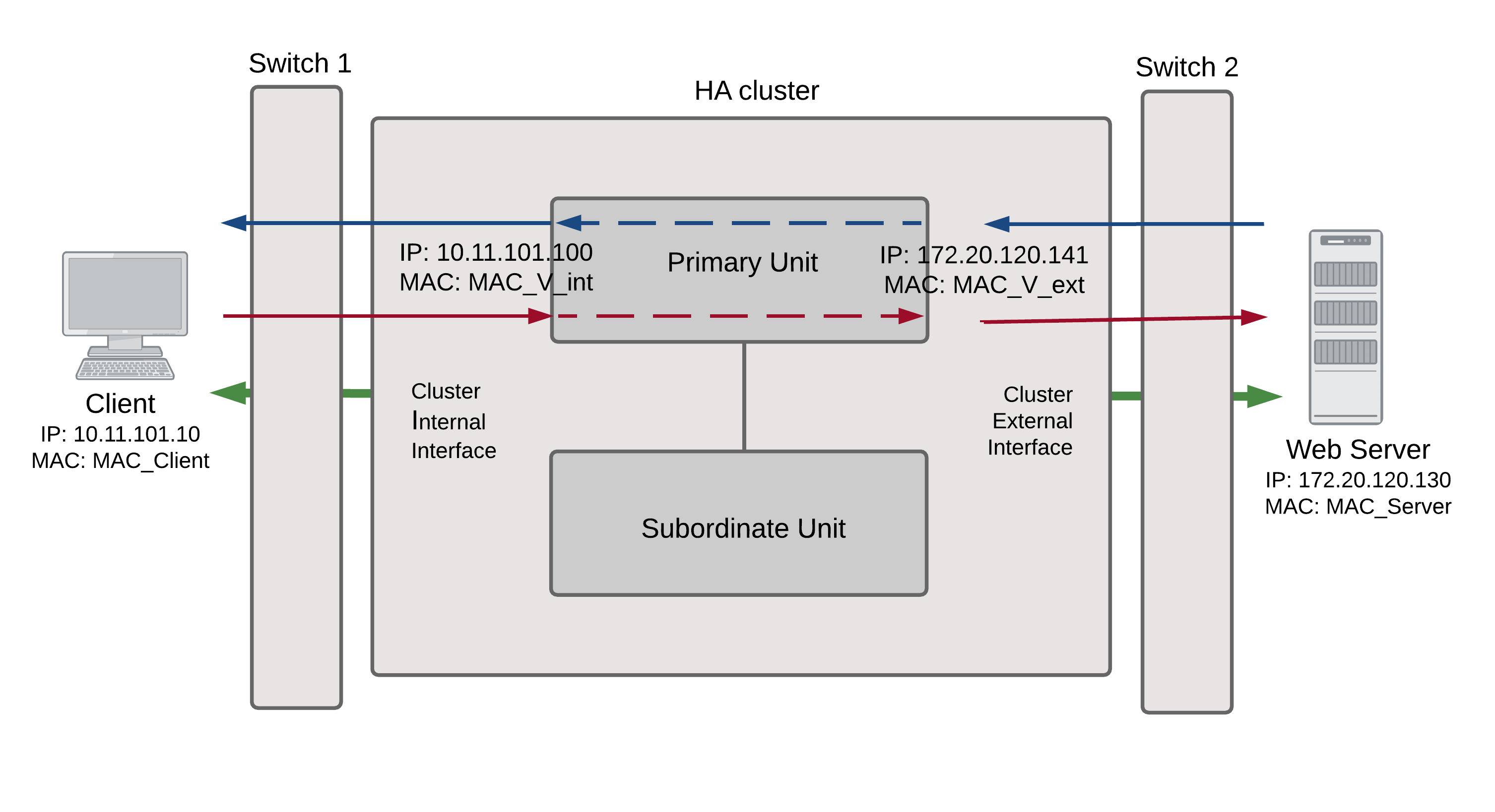
Packet flow from client to web server
- The client computer requests a connection from 10.11.101.10 to 172.20.120.130.
- The default route on the client computer recognizes 10.11.101.100 (the cluster IP address) as the gateway to the external network where the web server is located.
- The client computer issues an ARP request to 10.11.101.100.
- The primary unit intercepts the ARP request, and responds with the internal virtual MAC address (MAC_V_int) which corresponds to its IP address of 10.11.101.100.
- The client’s request packet reaches the primary unit internal interface.
| IP address | MAC address | |
| Source | 10.11.101.10 | MAC_Client |
| Destination | 172.20.120.130 | MAC_V_int |
- The primary unit processes the packet.
- The primary unit forwards the packet from its external interface to the web server.
| IP address | MAC address | |
| Source | 172.20.120.141 | MAC_V_ext |
| Destination | 172.20.120.130 | MAC_Server |
- The primary unit continues to process packets in this way unless a failover occurs.
Packet flow from web server to client
- When the web server responds to the client’s packet, the cluster external interface IP address (172.20.120.141) is recognized as the gateway to the internal network.
- The web server issues an ARP request to 172.20.120.141.
- The primary unit intercepts the ARP request, and responds with the external virtual MAC address (MAC_V_ext) which corresponds its IP address of 172.20.120.141.
- The web server then sends response packets to the primary unit external interface.
| IP address | MAC address | |
| Source | 172.20.120.130 | MAC_Server |
| Destination | 172.20.120.141 | MAC_V_ext |
- The primary unit processes the packet.
- The primary unit forwards the packet from its internal interface to the client.
| IP address | MAC address | |
| Source | 172.20.120.130 | MAC_V_int |
| Destination | 10.11.101.10 | MAC_Client |
- The primary unit continues to process packets in this way unless a failover occurs.
When a failover occurs
The following steps are followed after a device or link failure of the primary unit causes a failover.
- If the primary unit fails the subordinate unit becomes the primary unit.
- The new primary unit changes the MAC addresses of all of its interfaces to the HA virtual MAC addresses.
The new primary unit has the same IP addresses and MAC addresses as the failed primary unit.
- The new primary units sends gratuitous ARP packets from the internal interface to the 10.11.101.0 network to associate its internal IP address with the internal virtual MAC address.
- The new primary units sends gratuitous ARP packets to the 172.20.120.0 to associate its external IP address with the external virtual MAC address.
- Traffic sent to the cluster is now received and processed by the new primary unit.
If there were more than two cluster units in the original cluster, these remaining units would become subordinate units.
Transparent mode active-passive cluster packet flow
This section describes how packets are processed and how failover occurs in an active‑passive HA cluster running in Transparent mode. The cluster is installed on an internal network in front of a mail server and the client connects to the mail server through the Transparent mode cluster.
In an active-passive cluster operating in Transparent mode, two MAC addresses are involved in the communication between a client and a server when the primary unit processes a connection:
- Client MAC address (MAC_Client)
- Server MAC address (MAC_Server)
The HA virtual MAC addresses are not directly involved in communication between the client and the server. The client computer sends packets to the mail server and the mail server sends responses. In both cases the packets are intercepted and processed by the cluster.
The cluster’s presence on the network is transparent to the client and server computers. The primary unit sends gratuitous ARP packets to Switch 1 that associate all MAC addresses on the network segment connected to the cluster external interface with the HA virtual MAC address. The primary unit also sends gratuitous ARP packets to Switch 2 that associate all MAC addresses on the network segment connected to the cluster internal interface with the HA virtual MAC address. In both cases, this results in the switches sending packets to the primary unit interfaces.
Transparent mode active-passive packet flow
![]()
Packet flow from client to mail server
- The client computer requests a connection from 10.11.101.10 to 110.11.101.200.
- The client computer issues an ARP request to 10.11.101.200.
- The primary unit forwards the ARP request to the mail server.
- The mail server responds with its MAC address (MAC_Server) which corresponds to its IP address of 10.11.101.200. The primary unit returns the ARP response to the client computer.
- The client’s request packet reaches the primary unit internal interface.
| IP address | MAC address | |
| Source | 10.11.101.10 | MAC_Client |
| Destination | 10.11.101.200 | MAC_Server |
- The primary unit processes the packet.
- The primary unit forwards the packet from its external interface to the mail server.
| IP address | MAC address | |
| Source | 10.11.101.10 | MAC_Client |
| Destination | 10.11.101.200 | MAC_Server |
- The primary unit continues to process packets in this way unless a failover occurs.
Packet flow from mail server to client
- To respond to the client computer, the mail server issues an ARP request to 10.11.101.10.
- The primary unit forwards the ARP request to the client computer.
- The client computer responds with its MAC address (MAC_Client) which corresponds to its IP address of 10.11.101.10. The primary unit returns the ARP response to the mail server.
- The mail server’s response packet reaches the primary unit external interface.
| IP address | MAC address | |
| Source | 10.11.101.200 | MAC_Server |
| Destination | 10.11.101.10 | MAC_Client |
- The primary unit processes the packet.
- The primary unit forwards the packet from its internal interface to the client.
| IP address | MAC address | |
| Source | 10.11.101.200 | MAC_Server |
| Destination | 10.11.101.10 | MAC_Client |
- The primary unit continues to process packets in this way unless a failover occurs.
When a failover occurs
The following steps are followed after a device or link failure of the primary unit causes a failover.
- If the primary unit fails, the subordinate unit negotiates to become the primary unit.
- The new primary unit changes the MAC addresses of all of its interfaces to the HA virtual MAC address.
- The new primary units sends gratuitous ARP packets to switch 1 to associate its MAC address with the MAC addresses on the network segment connected to the external interface.
- The new primary units sends gratuitous ARP packets to switch 2 to associate its MAC address with the MAC addresses on the network segment connected to the internal interface.
- Traffic sent to the cluster is now received and processed by the new primary unit.
If there were more than two cluster units in the original cluster, these remaining units would become subordinate units.
Failover performance
This section describes the designed device and link failover times for a FortiGate cluster and also shows results of a failover performance test.
Device failover performance
By design FGCP device failover time is 2 seconds for a two-member cluster with ideal network and traffic conditions. If subsecond failover is enabled the failover time can drop below 1 second.
All cluster units regularly receive HA heartbeat packets from all other cluster units over the HA heartbeat link. If any cluster unit does not receive a heartbeat packet from any other cluster unit for 2 seconds, the cluster unit that has not sent heartbeat packets is considered to have failed.
It may take another few seconds for the cluster to negotiate and re-distribute communication sessions. Typically if subsecond failover is not enabled you can expect a failover time of 9 to 15 seconds depending on the cluster and network configuration. The failover time can also be increased by more complex configurations and or configurations with network equipment that is slow to respond.
You can change the hb-lost-threshold to increase or decrease the device failover time. See Modifying heartbeat timing for information about using hb‑lost-threshold, and other heartbeat timing settings.
Link failover performance
Link failover time is controlled by how long it takes for a cluster to synchronize the cluster link database. When a link failure occurs, the cluster unit that experienced the link failure uses HA heartbeat packets to broadcast the updated link database to all cluster units. When all cluster units have received the updated database the failover is complete.
It may take another few seconds for the cluster to negotiate and re-distribute communication sessions.
Reducing failover times
- Keep the network configuration as simple as possible with as few as possible network connections to the cluster.
- If possible operate the cluster in Transparent mode.
- Use high-performance switches to that the switches failover to interfaces connected to the new primary unit as quickly as possible.
- Use accelerated FortiGate interfaces. In some cases accelerated interfaces will reduce failover times.
- Make sure the FortiGate unit sends multiple gratuitous arp packets after a failover. In some cases, sending more gratuitous arp packets will cause connected network equipment to recognize the failover sooner. To send 10 gratuitous arp packets:
config system ha
set arps 10
end
- Reduce the time between gratuitous arp packets. This may also caused connected network equipment to recognize the failover sooner. To send 50 gratuitous arp packets with 1 second between each packet:
config system ha
set arps 50
set arps-interval 1
end
- Reduce the number of lost heartbeat packets and reduce the heartbeat interval timers to be able to more quickly detect a device failure. To set the lost heartbeat threshold to 3 packets and the heartbeat interval to 100 milliseconds:
config system ha
set hb-interval 1
set hb-lost-threshold 3
end
- Reduce the hello state hold down time to reduce the amount of the time the cluster waits before transitioning from the hello to the work state. To set the hello state hold down time to 5 seconds:
config system ha
set helo-holddown 5
end
- Enable sending a link failed signal after a link failover to make sure that attached network equipment responds a quickly as possible to a link failure. To enable the link failed signal:
config system ha
set link-failed-signal enable
end
Copyright © 2018 Fortinet, Inc. All Rights Reserved. | Terms of Service | Privacy Policy
