
FGCP HA with 802.3ad aggregated interfaces
On FortiGate models that support it you can use 802.3ad link aggregation to combine two or more interfaces into a single aggregated interface. 802.3ad Link Aggregation and it's management protocol, Link Aggregation Control Protocol (LACP) are a method for combining multiple physical links into a single logical link.This increases both potential throughput and network resiliency. Using LACP, traffic is distributed among the physical interfaces in the link, potentially resulting in increased performance.
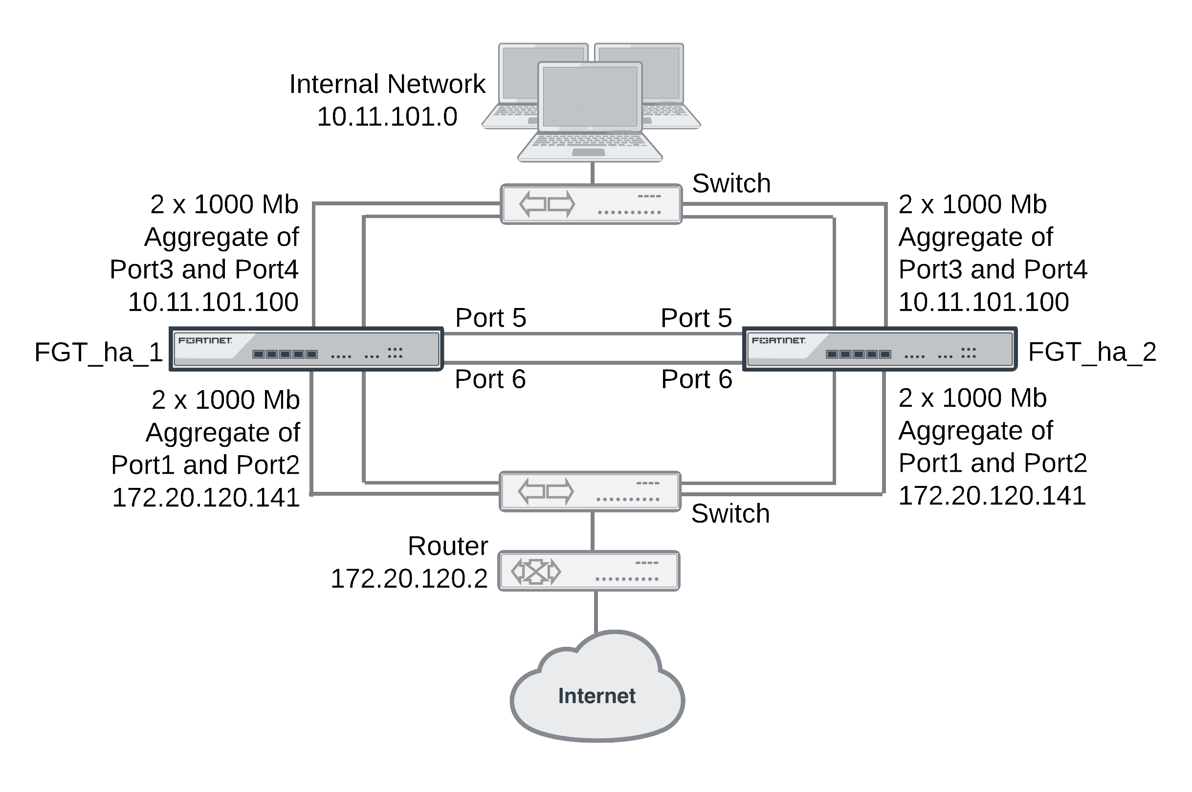
This example describes how to configure an HA cluster consisting of two FortiGate units with two aggregated 1000 Mb connections to the Internet using port1 and port2 and two aggregated 1000 Mb connections to the internal network using port3 and port4. The aggregated interfaces are also configured as HA monitored interfaces.
Each of the aggregate links connects to a different switch. Each switch is configured for link aggregation (2x1000Mb).
Example cluster with aggregate interfaces
HA interface monitoring, link failover, and 802.3ad aggregation
When monitoring the aggregated interface, HA interface monitoring treats the aggregated link as a single interface and does not monitor the individual physical interfaces in the link. HA interface monitoring registers the link to have failed only if all the physical interfaces in the link have failed. If only some of the physical interfaces in the link fail or become disconnected, HA considers the link to be operating normally.
HA MAC addresses and 802.3ad aggregation
If a configuration uses the Link Aggregate Control Protocol (LACP) (either passive or active), LACP is negotiated over all of the interfaces in any link. For a standalone FortiGate unit, the FortiGate LACP implementation uses the MAC address of the first interface in the link to uniquely identify that link. For example, a link consisting of port1 and port2 interfaces would have the MAC address of port1.
In an HA cluster, HA changes the MAC addresses of the cluster interfaces to virtual MAC addresses. An aggregate interface in a cluster acquires the virtual MAC address that would have been acquired by the first interface in the aggregate.
Link aggregation, HA failover performance, and HA mode
To operate an active-active or active-passive cluster with aggregated interfaces and for best performance of a cluster with aggregated interfaces, the switches used to connect the cluster unit aggregated interfaces together should support configuring multiple Link Aggregation (LAG) groups.
For example, the cluster shown above should be configured into two LAG groups on the external switch: one for the port1 and port2 aggregated interface of FGT_ha_1 and a second one for the port1 and port2 aggregate interface of FGT_ha_2. You should also be able to do the same on the internal switch for the port3 and port4 aggregated interfaces of each cluster unit.
As a result, the subordinate unit aggregated interfaces would participate in LACP negotiation while the cluster is operating. In an active-active mode cluster, packets could be redirected to the subordinate unit interfaces. As well, in active-active or active-passive mode, after a failover the subordinate unit can become a primary unit without having to perform LACP negotiation before it can process traffic. Performing LACP negotiation causes a minor failover delay.
However if you cannot configure multiple LAG groups on the switches, due to the primary and subordinate unit interfaces having the same MAC address, the switch will put all of the interfaces into the same LAG group which would disrupt the functioning of the cluster. To prevent this from happening, you must change the FortiGate aggregated interface configuration to prevent subordinate units from participating in LACP negotiation.
For example, use the following command to prevent subordinate units from participating in LACP negotiation with an aggregate interface named Port1_Port2:
config system interface
edit Port1_Port2
set lacp-ha-slave disable
end
As a result of this setting, subordinate unit aggregated interfaces cannot accept packets. This means that you cannot operate the cluster in active-active mode because in active‑active mode the subordinate units must be able to receive and process packets. Also, failover may take longer because after a failover the subordinate unit has to perform LACP negotiation before being able to process network traffic.
Also, it may also be necessary to configure the switch to use Passive or even Static mode for LACP to prevent the switch from sending packets to the subordinate unit interfaces, which won’t be able to process them.
Finally, in some cases depending on the LACP configuration of the switches, you may experience delayed failover if the FortiGate LACP configuration is not compatible with the switch LACP configuration. For example, in some cases setting the FortiGate LACP mode to static reduces the failover delay because the FortiGate unit does not perform LACP negotiation. However there is a potential problem with this configuration because static LACP does not send periodic LAC Protocol Data Unit (LACPDU) packets to test the connections. So a non-physical failure (for example, if a device is not responding because its too busy) may not be detected and packets could be lost or delayed.
General configuration steps
The section includes web-based manager and CLI procedures. These procedures assume that the FortiGate units are running the same FortiOS firmware build and are set to the factory default configuration.
General configuration steps
- Apply licenses to the FortiGate units to become the cluster.
- Configure the FortiGate units for HA operation.
- Change each unit’s host name.
- Configure HA.
- Connect the cluster to the network.
- View cluster status.
- Add basic configuration settings and configure the aggregated interfaces.
- Add a password for the admin administrative account.
- Add the aggregated interfaces.
- Disable
lacp-ha-slaveso that the subordinate unit does not send LACP packets. - Add a default route.
You could also configure aggregated interfaces in each FortiGate unit before the units form a cluster.
- Configure HA port monitoring for the aggregated interfaces.
Configuring active-passive HA cluster that includes aggregated interfaces - web-based manager
These procedures assume you are starting with two FortiGate units with factory default settings.
To configure the FortiGate units for HA operation
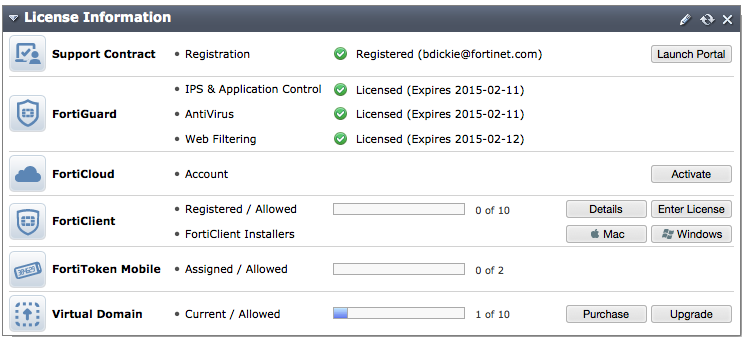
- Register and apply licenses to the FortiGate unit. This includes FortiCloud activation and FortiClient licensing and entering a license key if you purchased more than 10 Virtual Domains (VDOMS).
- You can also install any third-party certificates on the primary FortiGate before forming the cluster. Once the cluster is formed third-party certificates are synchronized to the backup FortiGate.
FortiToken licenses can be added at any time because they are synchronized to all cluster members. - On the System Information dashboard widget, beside Host Name select Change.
- Enter a new Host Name for this FortiGate unit.
| New Name | FGT_ha_1 |
- Select OK.
- Go to System > Config > HA and change the following settings.
| Mode | Active-Passive | |
| Group Name | example5.com | |
| Password | HA_pass_5 | |
| Heartbeat Interface | ||
| Enable | Priority | |
| port5 | Select | 50 |
| port6 | Select | 50 |
Since port3 and port4 will be used for an aggregated interface, you must change the HA heartbeat configuration to not use those interfaces.
- Select OK.
The FortiGate unit negotiates to establish an HA cluster. When you select OK you may temporarily lose connectivity with the FortiGate unit as the HA cluster negotiates and the FGCP changes the MAC address of the FortiGate unit interfaces. The MAC addresses of the FortiGate interfaces change to the following virtual MAC addresses:
- port1 interface virtual MAC:
00-09-0f-09-00-00 - port10 interface virtual MAC:
00-09-0f-09-00-01 - port11 interface virtual MAC:
00-09-0f-09-00-02 - port12 interface virtual MAC:
00-09-0f-09-00-03 - port13 interface virtual MAC:
00-09-0f-09-00-04 - port14 interface virtual MAC:
00-09-0f-09-00-05 - port15 interface virtual MAC:
00-09-0f-09-00-06 - port16 interface virtual MAC:
00-09-0f-09-00-07 - port17 interface virtual MAC:
00-09-0f-09-00-08 - port18 interface virtual MAC:
00-09-0f-09-00-09 - port19 interface virtual MAC:
00-09-0f-09-00-0a - port2 interface virtual MAC:
00-09-0f-09-00-0b - port20 interface virtual MAC:
00-09-0f-09-00-0c - port3 interface virtual MAC:
00-09-0f-09-00-0d - port4 interface virtual MAC:
00-09-0f-09-00-0e - port5 interface virtual MAC:
00-09-0f-09-00-0f - port6 interface virtual MAC:
00-09-0f-09-00-10 - port7 interface virtual MAC:
00-09-0f-09-00-11 - port8 interface virtual MAC:
00-09-0f-09-00-12 - port9 interface virtual MAC:
00-09-0f-09-00-13
To reconnect sooner, you can update the ARP table of your management PC by deleting the ARP table entry for the FortiGate unit (or just deleting all arp table entries). You may be able to delete the arp table of your management PC from a command prompt using a command similar to
arp -d.You can use the
get hardware nic(ordiagnose hardware deviceinfo nic) CLI command to view the virtual MAC address of any FortiGate unit interface. For example, use the following command to view the port1 interface virtual MAC address (Current_HWaddr) and the port1 permanent MAC address (Permanent_HWaddr):
get hardware nic port1
.
.
.
MAC: 00:09:0f:09:00:00
Permanent_HWaddr: 02:09:0f:78:18:c9
.
.
.
- Power off the first FortiGate unit.
- Repeat these steps for the second FortiGate unit.
Set the second FortiGate unit host name to:
| New Name | FGT_ha_2 |
To connect the cluster to the network
- Connect the port1 and port2 interfaces of FGT_ha_1 and FGT_ha_2 to a switch connected to the Internet.
Configure the switch so that the port1 and port2 of FGT_ha_1 make up an aggregated interface and port1 and port2 of FGT_ha_2 make up a second aggregated interface.
- Connect the port3 and port4 interfaces of FGT_ha_1 and FGT_ha_2 to a switch connected to the internal network.
Configure the switch so that the port3 and port4 of FGT_ha_1 make up an aggregated interface and port3 and port4 of FGT_ha_2 make up another aggregated interface.
- Connect the port5 interfaces of FGT_ha_1 and FGT_ha_2 together. You can use a crossover Ethernet cable or regular Ethernet cables and a switch.
- Connect the port5 interfaces of the cluster units together. You can use a crossover Ethernet cable or regular Ethernet cables and a switch.
- Power on the cluster units.
The units negotiate to choose the primary unit and the subordinate unit. This negotiation occurs with no user intervention and normally takes less than a minute.
When negotiation is complete, the cluster is ready to be configured for your network.
To view cluster status
Use the following steps to view the cluster dashboard and cluster members list to confirm that the cluster units are operating as a cluster.
- View the system dashboard.
The System Information dashboard widget shows the Cluster Name (example5.com) and the host names and serial numbers of the Cluster Members. The Unit Operation widget shows multiple cluster units.
- Go to System > Config > HA to view the cluster members list.
The list shows two cluster units, their host names, their roles in the cluster, and their priorities. You can use this list to confirm that the cluster is operating normally.
To troubleshoot the cluster configuration
See FGCP HA with 802.3ad aggregated interfaces to troubleshoot the cluster.
To add basic configuration settings and the aggregate interfaces
Use the following steps to add a few basic configuration settings.
- Log into the cluster web-based manager.
- Go to System > Admin > Administrators.
- Edit admin and select Change Password.
- Enter and confirm a new password.
- Select OK.
- Go to Router > Static > Static Routes and temporarily delete the default route.
You cannot add an interface to a aggregated interface if any settings (such as the default route) are configured for it.
- Go to System > Network > Interfaces and select Create New to add the aggregate interface to connect to the Internet.
- Set Type to 802.3ad Aggregate and configure the aggregate interface to be connected to the Internet:
| Name | Port1_Port2 |
| Physical Interface Members | port1, port2 |
| IP/Network Mask | 172.20.120.141/24 |
- Select OK.
- Select Create New to add the aggregate interface to connect to the internal network.
- Set Type to 802.3ad Aggregate and configure the aggregate interface to be connected to the Internet:
| Name | Port3_Port4 |
| Physical Interface Members | port3, port4 |
| IP/Netmask | 10.11.101.100/24 |
| Administrative Access | HTTPS, PING, SSH |
- Select OK.
The virtual MAC addresses of the FortiGate interfaces change to the following. Note that port1 and port2 both have the port1 virtual MAC address and port3 and port4 both have the port3 virtual MAC address:
- port1 interface virtual MAC:
00-09-0f-09-00-00 - port10 interface virtual MAC:
00-09-0f-09-00-01 - port11 interface virtual MAC:
00-09-0f-09-00-02 - port12 interface virtual MAC:
00-09-0f-09-00-03 - port13 interface virtual MAC:
00-09-0f-09-00-04 - port14 interface virtual MAC:
00-09-0f-09-00-05 - port15 interface virtual MAC:
00-09-0f-09-00-06 - port16 interface virtual MAC:
00-09-0f-09-00-07 - port17 interface virtual MAC:
00-09-0f-09-00-08 - port18 interface virtual MAC:
00-09-0f-09-00-09 - port19 interface virtual MAC:
00-09-0f-09-00-0a - port2 interface virtual MAC:
00-09-0f-09-00-00(same as port1) - port20 interface virtual MAC:
00-09-0f-09-00-0c - port3 interface virtual MAC:
00-09-0f-09-00-0d - port4 interface virtual MAC:
00-09-0f-09-00-0d(same as port3) - port5 interface virtual MAC:
00-09-0f-09-00-0f - port6 interface virtual MAC:
00-09-0f-09-00-10 - port7 interface virtual MAC:
00-09-0f-09-00-11 - port8 interface virtual MAC:
00-09-0f-09-00-12 - port9 interface virtual MAC:
00-09-0f-09-00-13
- Connect to the CLI and enter the following command to disable sending LACP packets from the subordinate unit:
config system interface
edit Port1_Port2
set lacp-ha-slave disable
next
edit Port3_Port4
set lacp-ha-slave disable
end
- Go to Router > Static > Static Routes.
- Add the default route.
| Destination IP/Mask | 0.0.0.0/0.0.0.0 |
| Gateway | 172.20.120.2 |
| Device | Port1_Port2 |
| Distance | 10 |
- Select OK.
To configure HA port monitoring for the aggregate interfaces
- Go to System > Config > HA.
- In the cluster members list, edit the primary unit.
- Configure the following port monitoring for the aggregate interfaces:
| Port Monitor | |
| Port1_Port2 | Select |
| Port3_Port4 | Select |
- Select OK.
Configuring active-passive HA cluster that includes aggregate interfaces - CLI
These procedures assume you are starting with two FortiGate units with factory default settings.
To configure the FortiGate units for HA operation
- Register and apply licenses to the FortiGate unit. This includes FortiCloud activation and FortiClient licensing, and entering a license key if you purchased more than 10 Virtual Domains (VDOMS).
- Install any third-party certificates on the FortiGate.
FortiToken licenses can be added at any time because they are synchronized to all cluster members. - Change the host name for this FortiGate unit:
config system global
set hostname FGT_ha_1
end
- Configure HA settings.
config system ha
set mode a-p
set group-name example5.com
set password HA_pass_5
set hbdev port5 50 port6 50
end
Since port3 and port4 will be used for an aggregated interface, you must change the HA heartbeat configuration.
The FortiGate unit negotiates to establish an HA cluster. You may temporarily lose connectivity with the FortiGate unit as the HA cluster negotiates and the FGCP changes the MAC address of the FortiGate unit interfaces. The MAC addresses of the FortiGate interfaces change to the following virtual MAC addresses:
- port1 interface virtual MAC:
00-09-0f-09-00-00 - port10 interface virtual MAC:
00-09-0f-09-00-01 - port11 interface virtual MAC:
00-09-0f-09-00-02 - port12 interface virtual MAC:
00-09-0f-09-00-03 - port13 interface virtual MAC:
00-09-0f-09-00-04 - port14 interface virtual MAC:
00-09-0f-09-00-05 - port15 interface virtual MAC:
00-09-0f-09-00-06 - port16 interface virtual MAC:
00-09-0f-09-00-07 - port17 interface virtual MAC:
00-09-0f-09-00-08 - port18 interface virtual MAC:
00-09-0f-09-00-09 - port19 interface virtual MAC:
00-09-0f-09-00-0a - port2 interface virtual MAC:
00-09-0f-09-00-0b - port20 interface virtual MAC:
00-09-0f-09-00-0c - port3 interface virtual MAC:
00-09-0f-09-00-0d - port4 interface virtual MAC:
00-09-0f-09-00-0e - port5 interface virtual MAC:
00-09-0f-09-00-0f - port6 interface virtual MAC:
00-09-0f-09-00-10 - port7 interface virtual MAC:
00-09-0f-09-00-11 - port8 interface virtual MAC:
00-09-0f-09-00-12 - port9 interface virtual MAC:
00-09-0f-09-00-13
To reconnect sooner, you can update the ARP table of your management PC by deleting the ARP table entry for the FortiGate unit (or just deleting all arp table entries). You may be able to delete the arp table of your management PC from a command prompt using a command similar to
arp -d.You can use the
get hardware nic(ordiagnose hardware deviceinfo nic) CLI command to view the virtual MAC address of any FortiGate unit interface. For example, use the following command to view the port1 interface virtual MAC address (Current_HWaddr) and the port1 permanent MAC address (Permanent_HWaddr):
get hardware nic port1
.
.
.
MAC: 00:09:0f:09:00:00
Permanent_HWaddr: 02:09:0f:78:18:c9
.
.
.
- Repeat these steps for the other FortiGate unit.
Set the other FortiGate unit host name to:
config system global
set hostname FGT_ha_2
end
To connect the cluster to the network
- Connect the port1 and port2 interfaces of FGT_ha_1 and FGT_ha_2 to a switch connected to the Internet.
Configure the switch so that the port1 and port2 of FGT_ha_1 make up an aggregated interface and port1 and port2 of FGT_ha_2 make up another aggregated interface.
- Connect the port3 and port4 interfaces of FGT_ha_1 and FGT_ha_2 to a switch connected to the internal network.
Configure the switch so that the port3 and port4 of FGT_ha_1 make up an interfaced and port3 and port4 of FGT_ha_2 make up another aggregated interface.
- Connect the port5 interfaces of FGT_ha_1 and FGT_ha_2 together. You can use a crossover Ethernet cable or regular Ethernet cables and a switch.
- Connect the port5 interfaces of the cluster units together. You can use a crossover Ethernet cable or regular Ethernet cables and a switch.
- Power on the cluster units.
The units start and negotiate to choose the primary unit and the subordinate unit. This negotiation occurs with no user intervention and normally takes less than a minute.
When negotiation is complete the cluster is ready to be configured for your network.
To view cluster status
Use the following steps to view cluster status from the CLI.
- Log into the CLI.
- Enter
get system statusto verify the HA status of the cluster unit that you logged into. Look for the following information in the command output.
Current HA mode: a-a, master
|
The cluster units are operating as a cluster and you have connected to the primary unit. |
Current HA mode: a-a, backup
|
The cluster units are operating as a cluster and you have connected to a subordinate unit. |
Current HA mode: standalone
|
The cluster unit is not operating in HA mode |
- Enter the following command to confirm the HA configuration of the cluster:
get system ha status
Model: XXXX
Mode: a-a
Group: 0
Debug: 0
ses_pickup: disable
Master:128 FGT_ha_2 FG600B3908600825 0
Slave :128 FGT_ha_1 FG600B3908600705 1
number of vcluster: 1
vcluster 1: work 169.254.0.1
Master:0 FG600B3908600825
Slave :1 FG600B3908600705
The command output shows both cluster units, their host names, their roles in the cluster, and their priorities. You can use this command to confirm that the cluster is operating normally. For example, if the command shows only one cluster unit then the other unit has left the cluster for some reason.
To troubleshoot the cluster configuration
See FGCP HA with 802.3ad aggregated interfaces to troubleshoot the cluster.
To add basic configuration settings and the aggregate interfaces
Use the following steps to add a few basic configuration settings and the aggregate interfaces.
- Add a password for the admin administrative account.
config system admin
edit admin
set password <psswrd>
end
- Temporarily delete the default route.
You cannot add an interface to an aggregate interface if any settings (such as the default route) are configured for it. In this example the index of the default route is 1.
config router static
delete 1
end
- Add the aggregate interfaces:
config system interface
edit Port1_Port2
set type aggregate
set lacp-ha-slave disable
set member port1 port2
set ip 172.20.120.141/24
set vdom root
next
edit Port3_Port4
set type aggregate
set lacp-ha-slave disable
set member port3 port4
set ip 10.11.101.100/24
set vdom root
end
The virtual MAC addresses of the FortiGate interfaces change to the following. Note that port1 and port2 both have the port1 virtual MAC address and port3 and port4 both have the port3 virtual MAC address:
- port1 interface virtual MAC:
00-09-0f-09-00-00 - port10 interface virtual MAC:
00-09-0f-09-00-01 - port11 interface virtual MAC:
00-09-0f-09-00-02 - port12 interface virtual MAC:
00-09-0f-09-00-03 - port13 interface virtual MAC:
00-09-0f-09-00-04 - port14 interface virtual MAC:
00-09-0f-09-00-05 - port15 interface virtual MAC:
00-09-0f-09-00-06 - port16 interface virtual MAC:
00-09-0f-09-00-07 - port17 interface virtual MAC:
00-09-0f-09-00-08 - port18 interface virtual MAC:
00-09-0f-09-00-09 - port19 interface virtual MAC:
00-09-0f-09-00-0a - port2 interface virtual MAC:
00-09-0f-09-00-00(same as port1) - port20 interface virtual MAC:
00-09-0f-09-00-0c - port3 interface virtual MAC:
00-09-0f-09-00-0d - port4 interface virtual MAC:
00-09-0f-09-00-0d(same as port3) - port5 interface virtual MAC:
00-09-0f-09-00-0f - port6 interface virtual MAC:
00-09-0f-09-00-10 - port7 interface virtual MAC:
00-09-0f-09-00-11 - port8 interface virtual MAC:
00-09-0f-09-00-12 - port9 interface virtual MAC:
00-09-0f-09-00-13
- Add the default route.
config router static
edit 1
set dst 0.0.0.0 0.0.0.0
set gateway 172.20.120.2
set device Port1_Port2
end
To configure HA port monitoring for the aggregate interfaces
- Configure HA port monitoring for the aggregate interfaces.
config system ha
set monitor Port1_Port2 Port3_Port4
end
Copyright © 2018 Fortinet, Inc. All Rights Reserved. | Terms of Service | Privacy Policy
