
Virtual clusters
This chapter provides an introduction to virtual clustering and also contains general procedures and configuration examples that describe how to configure FortiGate HA virtual clustering.
Virtual clustering overview
Virtual clustering is an extension of the FGCP for a cluster of 2 FortiGate units operating with multiple VDOMS enabled. Virtual clustering operates in active-passive mode to provide failover protection between two instances of a VDOM operating on two different cluster units. You can also operate virtual clustering in active-active mode to use HA load balancing to load balance sessions between cluster units. Alternatively, by distributing VDOM processing between the two cluster units you can also configure virtual clustering to provide load balancing by distributing sessions for different VDOMs to each cluster unit.
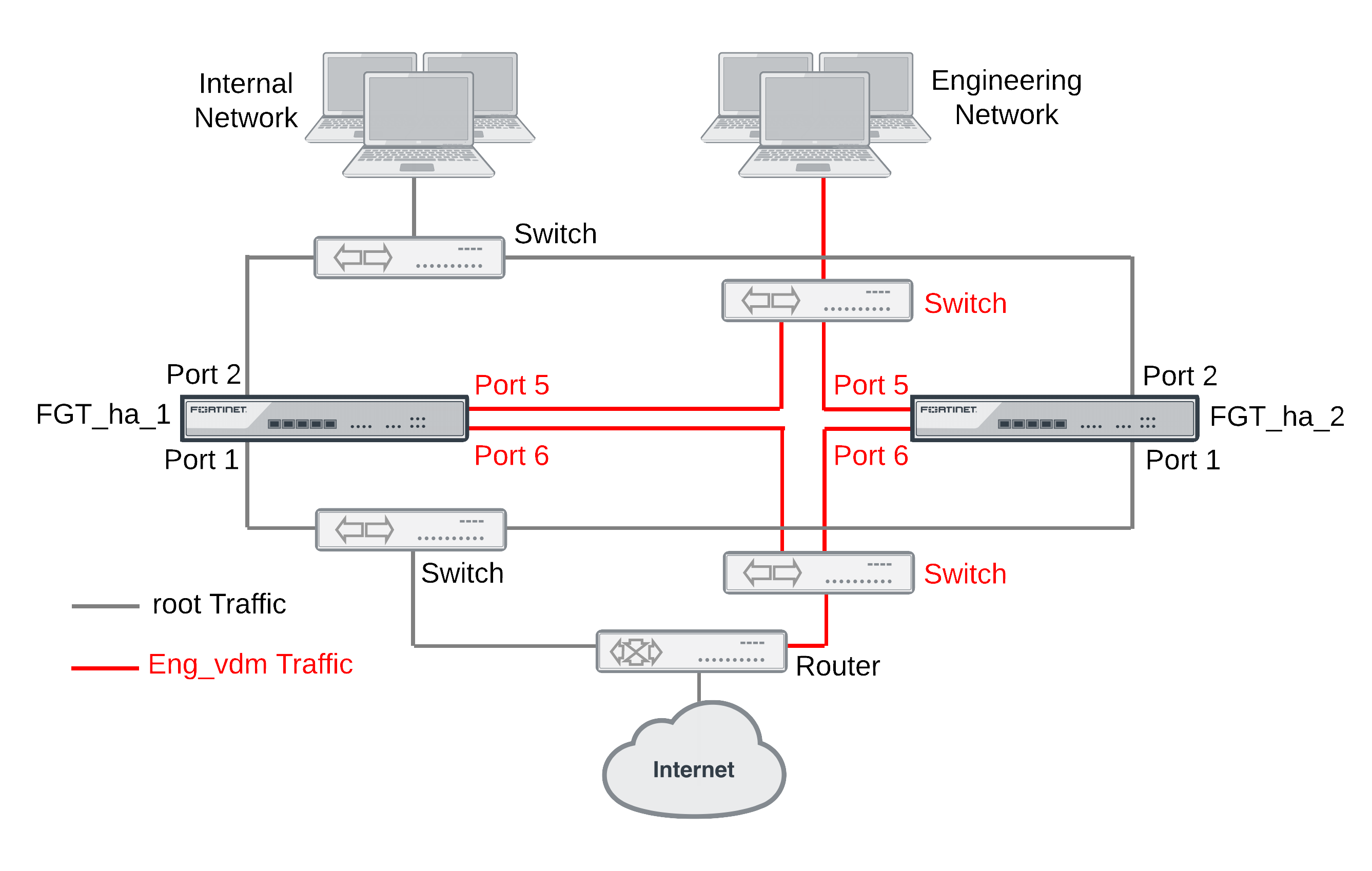
The figure below shows an example virtual cluster configuration consisting of two FortiGate units. The virtual cluster has two virtual domains, root and Eng_vdm.
The root virtual domain includes the port1 and port2 interfaces. The Eng_vdm virtual domain includes the port5 and port6 interfaces. The port3 and port4 interfaces (not shown in the diagram) are the HA heartbeat interfaces.
|
|
FortiGate virtual clustering is limited to a cluster of 2 FortiGate units with multiple VDOMs enabled. If you want to create a cluster of more than 2 FortiGate units operating with multiple VDOMS you could consider other solutions that either do not include multiple VDOMs in one cluster or employ a feature such as standalone session synchronization. See FortiGate Session Life Support Protocol (FGSP). |
Virtual clustering and failover protection
Virtual clustering operates on a cluster of two (and only two) FortiGate units with VDOMs enabled. Each VDOM creates a cluster between instances of the VDOMs on the two FortiGate units in the virtual cluster. All traffic to and from the VDOM stays within the VDOM and is processed by the VDOM. One cluster unit is the primary unit for each VDOM and one cluster unit is the subordinate unit for each VDOM. The primary unit processes all traffic for the VDOM. The subordinate unit does not process traffic for the VDOM. If a cluster unit fails, all traffic fails over to the cluster unit that is still operating.
Virtual clustering and heartbeat interfaces
The HA heartbeat provides the same HA services in a virtual clustering configuration as in a standard HA configuration. One set of HA heartbeat interfaces provides HA heartbeat services for all of the VDOMs in the cluster. You do not have to add a heartbeat interface for each VDOM.
Example virtual cluster
Virtual clustering and HA override
For a virtual cluster configuration, override is enabled by default for both virtual clusters when you:
- Enable VDOM partionning from the web-based manager by moving virtual domains to virtual cluster 2
- Enter
set vcluster2 enablefrom the CLIconfig system hacommand to enable virtual cluster 2.
Usually you would enable virtual cluster 2 and expect one cluster unit to be the primary unit for virtual cluster 1 and the other cluster unit to be the primary unit for virtual cluster 2. For this distribution to occur override must be enabled for both virtual clusters. Otherwise you will need to restart the cluster to force it to renegotiate.
|
|
If override is enabled the cluster may renegotiate too often.You can choose to disable override at any time. If you decide to disable override, for best results, you should disable it for both cluster units. |
For more information about HA override see HA override.
Virtual clustering and load balancing or VDOM partitioning
There are two ways to configure load balancing for virtual clustering. The first is to set the HA mode to active-active. The second is to configure VDOM partitioning. For virtual clustering, setting the HA Mode to active-active has the same result as active-active HA for a cluster without virtual domains. The primary unit receives all sessions and load balances them among the cluster units according to the load balancing schedule. All cluster units process traffic for all virtual domains.
In a VDOM partitioning virtual clustering configuration, the HA mode is set to active-passive. Even though virtual clustering operates in active-passive mode you can configure a form of load balancing by using VDOM partitioning to distribute traffic between both cluster units. To configure VDOM partitioning you set one cluster unit as the primary unit for some virtual domains and you set the other cluster unit as the primary unit for other virtual domains. All traffic for a virtual domain is processed by the primary unit for that virtual domain. You can control the distribution of traffic between the cluster units by adjusting which cluster unit is the primary unit for each virtual domain.
For example, you could have 4 VDOMs, two of which have a high traffic volume and two of which have a low traffic volume. You can configure each cluster unit to be the primary unit for one of the high volume VDOMs and one of the low volume VDOMs. As a result each cluster unit will be processing traffic for a high volume VDOM and a low volume VDOM, resulting in an even distribution of traffic between the cluster units. You can adjust the distribution at any time. For example, if a low volume VDOM becomes a high volume VDOM you can move it from one cluster unit to another until the best balance is achieved.
From the web-based manager you configure VDOM partitioning by setting the HA mode to active-passive and distributing virtual domains between Virtual Cluster 1 and Virtual Cluster 2. You can also configure different device priorities, port monitoring, and remote link failover, for Virtual Cluster 1 and Virtual Cluster 2.
|
|
The device priorities for virtual cluster 1 and virtual cluster 2 are not synchronized between the FortiGate units in the virtual cluster. You must configure these device priorities separately for each cluster unit. |
From the CLI you configure VDOM partitioning by setting the HA mode to a-p. Then you configure device priority, port monitoring, and remote link failover and specify the VDOMs to include in virtual cluster 1. You do the same for virtual cluster 2 by entering the config secondary-vcluster command.
Failover protection does not change. If one cluster unit fails, all sessions are processed by the remaining cluster unit. No traffic interruption occurs for the virtual domains for which the still functioning cluster unit was the primary unit. Traffic may be interrupted temporarily for virtual domains for which the failed unit was the primary unit while processing fails over to the still functioning cluster unit.
If the failed cluster unit restarts and rejoins the virtual cluster, VDOM partitioning load balancing is restored.
Configuring HA for virtual clustering
If your cluster uses VDOMs, you are configuring virtual clustering. Most virtual cluster HA options are the same as normal HA options. However, virtual clusters include VDOM partitioning options. Other differences between configuration options for regular HA and for virtual clustering HA are described below.
To configure HA options for a cluster with VDOMs enabled:
- Log into the global web-based manager and go to System > Config > HA.
- From the CLI, log into the Global Configuration:
The following example shows how to configure active-active virtual clustering:
config global
config system ha
set mode a-a
set group-name vexample1.com
set password vHA_pass_1
end
end
The following example shows how to configure active-passive virtual clustering:
config global
config system ha
set mode a-p
set group-name vexample1.com
set password vHA_pass_1
end
end
The following example shows how to configure VDOM partitioning for virtual clustering. In the example, the FortiGate unit is configured with three VDOMs (domain_1, domain_2, and domain_3) in addition to the root VDOM. The example shows how to set up a basic HA configuration that sets the device priority of virtual cluster 1 to 200. The example also shows how to enable vcluster2, how to set the device priority of virtual cluster 2 to 100 and how to add the virtual domains domain_2 and domain_3 to virtual cluster 2.
When you enable multiple VDOMs, vcluster2 is enabled by default. Even so the command to enable vcluster2 is included in this example in case for some reason it has been disabled. When vcluster2 is enabled, override is also enabled.
The result of this configuration would be that the cluster unit that you are logged into becomes the primary unit for virtual cluster 1. This cluster unit processes all traffic for the root and domain_1 virtual domains.
config global
config system ha
set mode a-p
set group-name vexample1.com
set password vHA_pass_1
set priority 200
set vcluster2 enable
config secondary-vcluster
set vdom domain_2 domain_3
set priority 100
end
end
end
The following example shows how to use the execute ha manage command to change the device priorities for virtual cluster 1 and virtual cluster 2 for the other unit in the cluster. The commands set the device priority of virtual cluster 1 to 100 and virtual cluster 2 to 200.
The result of this configuration would be that the other cluster unit becomes the primary unit for virtual cluster 2. This other cluster unit would process all traffic for the domain_2 and domain_3 virtual domains.
config global
execute ha manage 1
config system ha
set priority 100
set vcluster2 enable
config secondary-vcluster
set priority 200
end
end
end
end
Example virtual clustering with two VDOMs and VDOM partitioning
This section describes how to configure the example virtual clustering configuration shown below. This configuration includes two virtual domains, root and Eng_vdm and includes VDOM partitioning that sends all root VDOM traffic to FGT_ha_1 and all Eng_vdom VDOM traffic to FGT_ha_2. The traffic from the internal network and the engineering network is distributed between the two FortiGate units in the virtual cluster. If one of the cluster units fails, the remaining unit will process traffic for both VDOMs.
The procedures in this example describe some of many possible sequences of steps for configuring virtual clustering. For simplicity many of these procedures assume that you are starting with new FortiGate units set to the factory default configuration. However, this is not a requirement for a successful HA deployment. FortiGate HA is flexible enough to support a successful configuration from many different starting points.
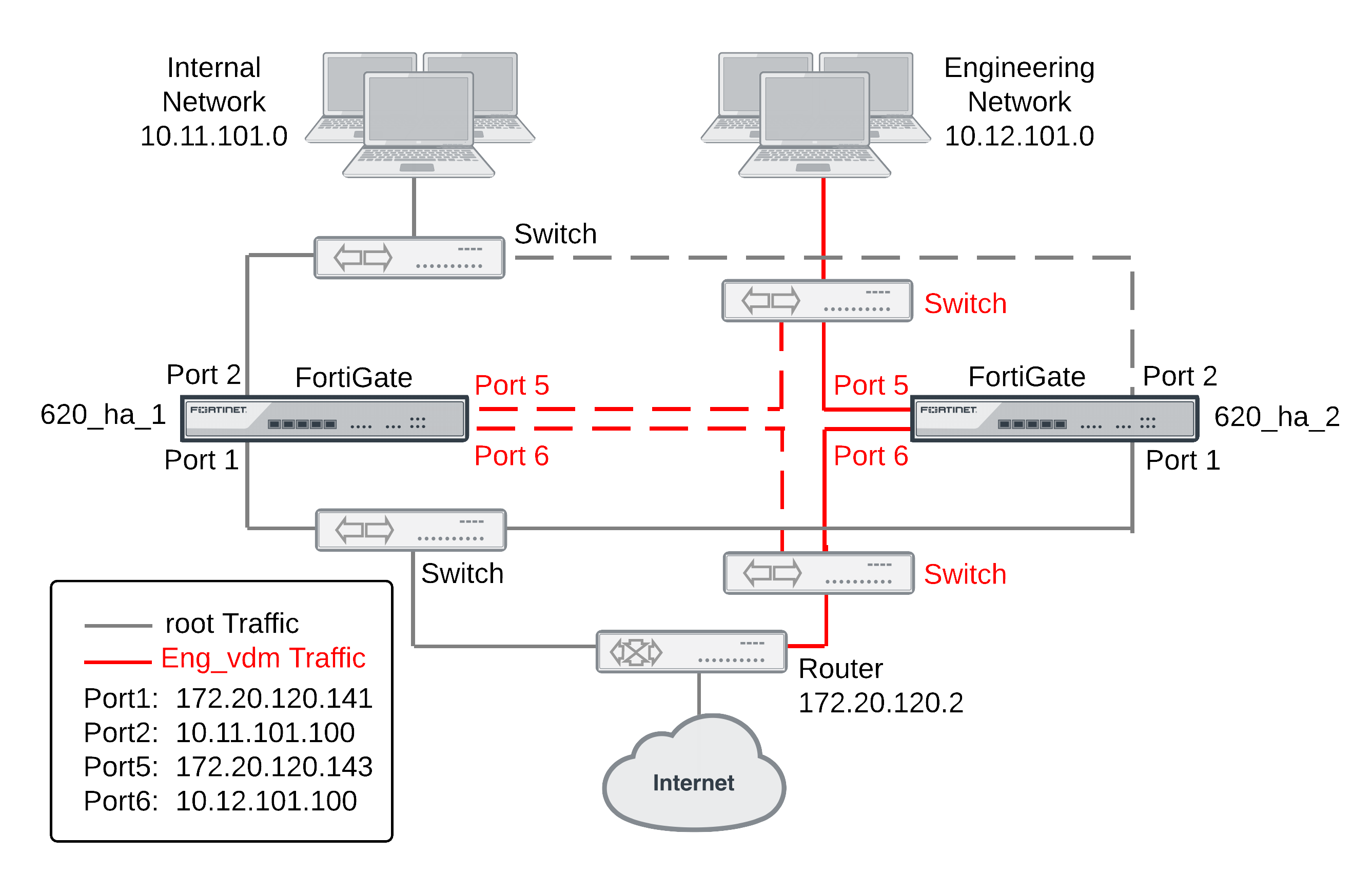
Example virtual clustering network topology
The following figure shows a typical FortiGate HA virtual cluster consisting of two FortiGate units (FGT_ha_1 and FGT_ha_2) connected to and internal network, an engineering network and the Internet. To simplify the diagram the heartbeat connections are not shown.
The traffic from the internal network is processed by the root VDOM, which includes the port1 and port2 interfaces. The traffic from the engineering network is processed by the Eng_vdm VDOM, which includes the port5 and port6 interfaces. VDOM partitioning is configured so that all traffic from the internal network is processed by FGT_ha_1 and all traffic from the engineering network is processed by FGT_ha_2.
This virtual cluster uses the default FortiGate heartbeat interfaces (port3 and port4).
Example virtual cluster showing VDOM partitioning
General configuration steps
The section includes web-based manager and CLI procedures. These procedures assume that the FortiGate units are running the same FortiOS firmware build and are set to the factory default configuration.
General configuration steps
- Apply licenses to the FortiGate units to become the cluster.
- Configure the FortiGate units for HA operation.
- Optionally change each unit’s host name.
- Configure HA.
- Connect the cluster to the network.
- Configure VDOM settings for the cluster:
- Enable multiple VDOMs.
- Add the Eng_vdm VDOM.
- Add port5 and port6 to the Eng_vdom.
- Configure VDOM partitioning.
- Confirm that the cluster units are operating as a virtual cluster and add basic configuration settings to the cluster.
- View cluster status from the web-based manager or CLI.
- Add a password for the admin administrative account.
- Change the IP addresses and netmasks of the port1, port2, port5, and port6 interfaces.
- Add a default routes to each VDOM.
Configuring virtual clustering with two VDOMs and VDOM partitioning - web-based manager
These procedures assume you are starting with two FortiGate units with factory default settings.
To configure the FortiGate units for HA operation
- Register and apply licenses to the FortiGate unit. This includes FortiCloud activation and FortiClient licensing, and entering a license key if you purchased more than 10 Virtual Domains (VDOMS).

- You can also install any third-party certificates on the primary FortiGate before forming the cluster. Once the cluster is formed third-party certificates are synchronized to the backup FortiGate.
FortiToken licenses can be added at any time because they are synchronized to all cluster members. - On the System Information dashboard widget, beside Host Name select Change.
- Enter a new Host Name for this FortiGate unit.
| New Name | FGT_ha_1 |
- Select OK.
- Go to System > Config > HA and change the following settings.
| Mode | Active-Passive |
| Group Name | vexample2.com |
| Password | vHA_pass_2 |
- Select OK.
The FortiGate unit negotiates to establish an HA cluster. When you select OK you may temporarily lose connectivity with the FortiGate unit as the HA cluster negotiates and the FGCP changes the MAC address of the FortiGate unit interfaces (see Cluster virtual MAC addresses). The MAC addresses of the FortiGate interfaces change to the following virtual MAC addresses:
- port1 interface virtual MAC:
00-09-0f-09-00-00 - port10 interface virtual MAC:
00-09-0f-09-00-01 - port11 interface virtual MAC:
00-09-0f-09-00-02 - port12 interface virtual MAC:
00-09-0f-09-00-03 - port13 interface virtual MAC:
00-09-0f-09-00-04 - port14 interface virtual MAC:
00-09-0f-09-00-05 - port15 interface virtual MAC:
00-09-0f-09-00-06 - port16 interface virtual MAC:
00-09-0f-09-00-07 - port17 interface virtual MAC:
00-09-0f-09-00-08 - port18 interface virtual MAC:
00-09-0f-09-00-09 - port19 interface virtual MAC:
00-09-0f-09-00-0a - port2 interface virtual MAC:
00-09-0f-09-00-0b - port20 interface virtual MAC:
00-09-0f-09-00-0c - port3 interface virtual MAC:
00-09-0f-09-00-0d - port4 interface virtual MAC:
00-09-0f-09-00-0e - port5 interface virtual MAC:
00-09-0f-09-00-0f - port6 interface virtual MAC:
00-09-0f-09-00-10 - port7 interface virtual MAC:
00-09-0f-09-00-11 - port8 interface virtual MAC:
00-09-0f-09-00-12 - port9 interface virtual MAC:
00-09-0f-09-00-13
To be able to reconnect sooner, you can update the ARP table of your management PC by deleting the ARP table entry for the FortiGate unit (or just deleting all arp table entries). You may be able to delete the arp table of your management PC from a command prompt using a command similar to
arp -d.You can use the
get hardware nic(ordiagnose hardware deviceinfo nic) CLI command to view the virtual MAC address of any FortiGate unit interface. For example, use the following command to view the port1 interface virtual MAC address (Current_HWaddr) and the port1 permanent MAC address (Permanent_HWaddr):
get hardware nic port1
.
.
.
MAC: 00:09:0f:09:00:00
Permanent_HWaddr: 02:09:0f:78:18:c9
.
.
.
- Power off the first FortiGate unit.
- Repeat these steps for the second FortiGate unit.
Set the second FortiGate unit host name to:
| New Name | FGT_ha_2 |
To connect the cluster to the network
- Connect the port1 interfaces of FGT_ha_1 and FGT_ha_2 to a switch connected to the Internet.
- Connect the port5 interfaces of FGT_ha_1 and FGT_ha_2 to switch connected to the Internet.
You could use the same switch for the port1 and port5 interfaces.
- Connect the port2 interfaces of FGT_ha_1 and FGT_ha_2 to a switch connected to the internal network.
- Connect the port6 interfaces of FGT_ha_1 and FGT_ha_2 to a switch connected to the engineering network.
- Connect the port3 interfaces of the cluster units together. You can use a crossover Ethernet cable or regular Ethernet cables and a switch.
- Connect the port4 interfaces of the cluster units together. You can use a crossover Ethernet cable or regular Ethernet cables and a switch.
- Power on the cluster units.
The units start and negotiate to choose the primary unit and the subordinate unit. This negotiation occurs with no user intervention.
When negotiation is complete you can continue.
To configure VDOM settings for the cluster
- Log into the web-based manager.
- On the System Information dashboard widget, beside Virtual Domain select Enable.
- Select OK and then log back into the web-based manager.
- Go to System > VDOM and select Create New to add a new VDOM.
| Name | Eng_vdm |
- Go to System > Network > Interfaces.
- Edit the port5 interface, add it to the Eng_vdm VDOM and configure other interface settings:
| Alias | Engineering_external |
| Virtual Domain | Eng_vdm |
| IP/Netmask | 172.20.120.143/24 |
- Select OK.
- Edit the port6 interface, add it to the Eng_vdm VDOM and configure other interface settings:
| Alias | Engineering_internal |
| Virtual Domain | Eng_vdm |
| IP/Netmask | 10.120.101.100/24 |
| Administrative Access | HTTPS, PING, SSH |
- Select OK.
To add a default route to each VDOM
- Go to System > VDOM and Enter the root VDOM.
- Go to Router > Static > Static Routes.
- Change the default route.
| Destination IP/Mask | 0.0.0.0/0.0.0.0 |
| Gateway | 172.20.120.2 |
| Device | port1 |
| Distance | 10 |
- Select Global.
- Go to System > VDOM and Enter the Eng_vdm VDOM.
- Go to Router > Static > Static Routes.
- Change the default route.
| Destination IP/Mask | 0.0.0.0/0.0.0.0 |
| Gateway | 172.20.120.2 |
| Device | port5 |
| Distance | 10 |
To configure VDOM partitioning
- Go to System > Config > HA.
The cluster members shows two cluster units in Virtual Cluster 1.
- Edit the cluster unit with the Role of MASTER.
- Change VDOM partitioning to move the Eng_vdm to the Virtual Cluster 2 list.
- Select OK.
- Change the Virtual Cluster 1 and Virtual Cluster 2 device priorities for each cluster unit to the following:
| Device Priority | ||
| Host Name | Virtual Cluster 1 | Virtual Cluster 2 |
| FGT_ha_1 | 200 | 100 |
| FGT_ha_2 | 100 | 200 |
You can do this by editing the HA configurations of each cluster unit in the cluster members list and changing device priorities.
Since the device priority of Virtual Cluster 1 is highest for FGT_ha_1 and since the root VDOM is in Virtual Cluster 1, all traffic for the root VDOM is processed by FGT_ha_1.
Since the device priority of Virtual Cluster 2 is highest for FGT_ha_2 and since the Eng_vdm VDOM is in Virtual Cluster 2, all traffic for the Eng_vdm VDOM is processed by FGT_ha_2.
To view cluster status and verify the VDOM partitioning configuration
- Log into the web-based manager.
- Go to System > Config > HA.
The cluster members list should show the following:
- Virtual Cluster 1 contains the root VDOM.
- FGT_ha_1 is the primary unit (master) for Virtual Cluster 1.
- Virtual Cluster 2 contains the Eng_vdm VDOM.
- FGT_ha_2 is the primary unit (master) for Virtual Cluster 2.
To test the VDOM partitioning configuration
You can do the following to confirm that traffic for the root VDOM is processed by FGT_ha_1 and traffic for the Eng_vdm is processed by FGT_ha_2.
- Log into the web-based manager by connecting to port2 using IP address 10.11.101.100.
You will log into FGT_ha_1 because port2 is in the root VDOM and all traffic for this VDOM is processed by FGT_ha_1. You can confirm that you have logged into FGT_ha_1 by checking the host name on the System Information dashboard widget.
- Log into the web-based manager by connecting to port6 using IP address 10.12.101.100.
You will log into FGT_ha_2 because port6 is in the Eng_vdm VDOM and all traffic for this VDOM is processed by FGT_ha_2.
- Add security policies to the root virtual domain that allows communication from the internal network to the Internet and connect to the Internet from the internal network.
- Log into the web-based manager and go to Config > System > HA and select View HA Statistics.
The statistics display shows more active sessions, total packets, network utilization, and total bytes for the FGT_ha_1 unit.
- Add security policies to the Eng_vdm virtual domain that allow communication from the engineering network to the Internet and connect to the Internet from the engineering network.
- Log into the web-based manager and go to Config > System > HA and select View HA Statistics.
The statistics display shows more active sessions, total packets, network utilization, and total bytes for the FGT_ha_2 unit.
Configuring virtual clustering with two VDOMs and VDOM partitioning - CLI
These procedures assume you are starting with two FortiGate units with factory default settings.
To configure the FortiGate units for HA operation
- Register and apply licenses to the FortiGate unit. This includes FortiCloud activation and FortiClient licensing, and entering a license key if you purchased more than 10 Virtual Domains (VDOMS).
- You can also install any third-party certificates on the primary FortiGate before forming the cluster. Once the cluster is formed third-party certificates are synchronized to the backup FortiGate.
FortiToken licenses can be added at any time because they are synchronized to all cluster members. - Change the host name for this FortiGate unit:
config system global
set hostname FGT_ha_1
end
- Configure HA settings.
config system ha
set mode a-p
set group-name vexample2.com
set password vHA_pass_2
end
The FortiGate unit negotiates to establish an HA cluster. You may temporarily lose connectivity with the FortiGate unit as the HA cluster negotiates and the FGCP changes the MAC address of the FortiGate unit interfaces (see Cluster virtual MAC addresses). The MAC addresses of the FortiGate interfaces change to the following virtual MAC addresses:
- port1 interface virtual MAC:
00-09-0f-09-00-00 - port10 interface virtual MAC:
00-09-0f-09-00-01 - port11 interface virtual MAC:
00-09-0f-09-00-02 - port12 interface virtual MAC:
00-09-0f-09-00-03 - port13 interface virtual MAC:
00-09-0f-09-00-04 - port14 interface virtual MAC:
00-09-0f-09-00-05 - port15 interface virtual MAC:
00-09-0f-09-00-06 - port16 interface virtual MAC:
00-09-0f-09-00-07 - port17 interface virtual MAC:
00-09-0f-09-00-08 - port18 interface virtual MAC:
00-09-0f-09-00-09 - port19 interface virtual MAC:
00-09-0f-09-00-0a - port2 interface virtual MAC:
00-09-0f-09-00-0b - port20 interface virtual MAC:
00-09-0f-09-00-0c - port3 interface virtual MAC:
00-09-0f-09-00-0d - port4 interface virtual MAC:
00-09-0f-09-00-0e - port5 interface virtual MAC:
00-09-0f-09-00-0f - port6 interface virtual MAC:
00-09-0f-09-00-10 - port7 interface virtual MAC:
00-09-0f-09-00-11 - port8 interface virtual MAC:
00-09-0f-09-00-12 - port9 interface virtual MAC:
00-09-0f-09-00-13
To be able to reconnect sooner, you can update the ARP table of your management PC by deleting the ARP table entry for the FortiGate unit (or just deleting all arp table entries). You may be able to delete the arp table of your management PC from a command prompt using a command similar to
arp -d.You can use the
get hardware nic(ordiagnose hardware deviceinfo nic) CLI command to view the virtual MAC address of any FortiGate unit interface. For example, use the following command to view the port1 interface virtual MAC address (Current_HWaddr) and the port1 permanent MAC address (Permanent_HWaddr):
get hardware nic port1
.
.
.
MAC: 00:09:0f:09:00:00
Permanent_HWaddr: 02:09:0f:78:18:c9
.
.
.
- Power off the first FortiGate unit.
- Repeat these steps for the second FortiGate unit.
Set the other FortiGate unit host name to:
config system global
set hostname FGT_ha_2
end
To connect the cluster to the network
- Connect the port1 interfaces of FGT_ha_1 and FGT_ha_2 to a switch connected to the Internet.
- Connect the port5 interfaces of FGT_ha_1 and FGT_ha_2 to switch connected to the Internet.
You could use the same switch for port1 and port5.
- Connect the port2 interfaces of FGT_ha_1 and FGT_ha_2 to a switch connected to the internal network.
- Connect the port6 interfaces of FGT_ha_1 and FGT_ha_2 to a switch connected to the engineering network.
- Connect the port3 interfaces of the cluster units together. You can use a crossover Ethernet cable or regular Ethernet cables and a switch.
- Connect the port4 interfaces of the cluster units together. You can use a crossover Ethernet cable or regular Ethernet cables and a switch.
- Power on the cluster units.
The units start and negotiate to choose the primary unit and the subordinate unit. This negotiation occurs with no user intervention.
When negotiation is complete you can continue.
To configure VDOM settings for the cluster
- Log into the CLI.
- Enter the following command to enable multiple VDOMs for the cluster.
config system global
set vdom-admin enable
end
- Log back into the CLI.
- Enter the following command to add the Eng_vdm VDOM:
config vdom
edit Eng_vdm
end
- Edit the port5 interface, add it to the Eng_vdm VDOM and configure other interface settings:
config global
config system interface
edit port5
set vdom Eng_vdm
set alias Engineering_external
set ip 172.20.12.143/24
next
edit port6
set vdom Eng_vdm
set alias Engineering_internal
set ip 10.120.101.100/24
end
end
To add a default route to each VDOM
- Enter the following command to add default routes to the root and Eng_vdm VDOMs.
config vdom
edit root
config router static
edit 1
set dst 0.0.0.0/0.0.0.0
set gateway 172.20.120.2
set device port1
end
next
edit Eng_vdm
config router static
edit 1
set dst 0.0.0.0/0.0.0.0
set gateway 172.20.120.2
set device port5
end
end
To configure VDOM partitioning
- Enter the
get system ha statuscommand to view cluster unit status:
For example, from the FGT_ha_2 cluster unit CLI:
config global
get system ha status
Model: XXXX
Mode: a-p
Group: 0
Debug: 0
ses_pickup: disable
Master:128 FGT_ha_2 FG600B3908600825 0
Slave :128 FGT_ha_1 FG600B3908600705 1
number of vcluster: 1
vcluster 1: work 169.254.0.1
Master:0 FG600B3908600825
Slave :1 FG600B3908600705
This command output shows that VDOM partitioning has not been configured because only virtual cluster 1 is shown. The command output also shows that the FGT_ha_2 is the primary unit for the cluster and for virtual cluster 1 because this cluster unit has the highest serial number
- Enter the following commands to configure VDOM partitioning:
config global
config system ha
set vcluster2 enable
config secondary-vcluster
set vdom Eng_vdm
end
end
end
- Enter the
get system ha statuscommand to view cluster unit status:
For example, from the FGT_ha_2 cluster unit CLI:
config global
get system ha status
Model: XXXX
Mode: a-p
Group: 0
Debug: 0
ses_pickup: disable
Master:128 FGT_ha_2 FG600B3908600825 0
Slave :128 FGT_ha_1 FG600B3908600705 1
number of vcluster: 2
vcluster 1: work 169.254.0.1
Master:0 FG600B3908600825
Slave :1 FG600B3908600705
vcluster 2: work 169.254.0.1
Master:0 FG600B3908600825
Slave :1 FG600B3908600705
This command output shows VDOM partitioning has been configured because both virtual cluster 1 and virtual cluster 2 are visible. However the configuration is not complete because FGT_ha_2 is the primary unit for both virtual clusters. The command output shows this because under both vcluster entries the
Masterentry shows FG600B3908600825, which is the serial number of FGT_ha_2. As a result of this configuration, FGT_ha_2 processes traffic for both VDOMs and FGT_ha_1 does not process any traffic.
- Change the Virtual Cluster 1 and Virtual Cluster 2 device priorities for each cluster unit so that FGT_ha_1 processes virtual cluster 1 traffic and FGT_ha_2 processes virtual cluster 2 traffic.
Since the root VDOM is in virtual cluster 1 and the Eng_vdm VDOM is in virtual cluster 2 the result of this configuration will be that FGT_ha_1 will process all root VDOM traffic and FGT_ha_2 will process all Eng_vdm traffic. You make this happen by changing the cluster unit device priorities for each virtual cluster. You could use the following settings:
| Device Priority | ||
| Host Name | Virtual Cluster 1 | Virtual Cluster 2 |
| FGT_ha_1 | 200 | 100 |
| FGT_ha_2 | 100 | 200 |
Since the device priority is not synchronized you can edit the device priorities of each virtual cluster on each FortiGate unit separately. To do this:
- Log into the CLI and note the FortiGate unit you have actually logged into (for example, by checking the host name displayed in the CLI prompt).
- Change the virtual cluster 1 and 2 device priorities for this cluster unit.
- Then use the
execute ha managecommand to log into the other cluster unit CLI and set its virtual cluster 1 and 2 device priorities.
Enter the following commands from the FGT_ha_1 cluster unit CLI:
config global
config system ha
set priority 200
config secondary-vcluster
set priority 100
end
end
end
Enter the following commands from the FGT_ha_2 cluster unit CLI:
config global
config system ha
set priority 100
config secondary-vcluster
set priority 200
end
end
end
|
|
The cluster may renegotiate during this step resulting in a temporary loss of connection to the CLI and a temporary service interruption. |
Since the device priority of Virtual Cluster 1 is highest for FGT_ha_1 and since the root VDOM is in Virtual Cluster 1, all traffic for the root VDOM is processed by FGT_ha_1.
Since the device priority of Virtual Cluster 2 is highest for FGT_ha_2 and since the Eng_vdm VDOM is in Virtual Cluster 2, all traffic for the Eng_vdm VDOM is processed by FGT_ha_2.
To verify the VDOM partitioning configuration
- Log into the FGT_ha_2 cluster unit CLI and enter the following command:
config global
get system ha status
Model: XXXX
Mode: a-p
Group: 0
Debug: 0
ses_pickup: disable
Slave :100 FGT_ha_2 FG600B3908600825 0
Master:200 FGT_ha_1 FG600B3908600705 1
number of vcluster: 2
vcluster 1: standby 169.254.0.2
Slave :1 FG600B3908600825
Master:0 FG600B3908600705
vcluster 2: work 169.254.0.1
Master:0 FG600B3908600825
Slave :1 FG600B3908600705
The command output shows that FGT_ha_1 is the primary unit for virtual cluster 1 (because the command output show the
Masterof virtual cluster 1 is the serial number of FGT_ha_1) and that FGT_ha_2 is the primary unit for virtual cluster 2.If you enter the same command from the FGT_ha_1 CLI the same information is displayed but in a different order. The command always displays the status of the cluster unit that you are logged into first.
config global
get system ha status
Model: XXXX
Mode: a-p
Group: 0
Debug: 0
ses_pickup: disable
Master:200 FGT_ha_1 FG600B3908600705 1
Slave :100 FGT_ha_2 FG600B3908600825 0
number of vcluster: 2
vcluster 1: work 169.254.0.2
Master:0 FG600B3908600705
Slave :1 FG600B3908600825
vcluster 2: standby 169.254.0.1
Slave :1 FG600B3908600705
Master:0 FG600B3908600825
To test the VDOM partitioning configuration
You can do the following to confirm that traffic for the root VDOM is processed by FGT_ha_1 and traffic for the Eng_vdm is processed by FGT_ha_2. These steps assume the cluster is operating correctly.
- Log into the CLI by connecting to port2 using IP address 10.11.101.100.
You will log into FGT_ha_1 because port2 is in the root VDOM and all traffic for this VDOM is processed by FGT_ha_1. You can confirm that you have logged into FGT_ha_1 by checking the host name in the CLI prompt. Also the
get system statuscommand displays the status of the FGT_ha_1 cluster unit.
- Log into the web-based manager or CLI by connecting to port6 using IP address 10.12.101.100.
You will log into FGT_ha_2 because port6 is in the Eng_vdm VDOM and all traffic for this VDOM is processed by FGT_ha_2.
- Add security policies to the root virtual domain that allow communication from the internal network to the Internet and connect to the Internet from the internal network.
- Log into the web-based manager and go to Config > System > HA and select View HA Statistics.
The statistics display shows more active sessions, total packets, network utilization, and total bytes for the FGT_ha_1 unit.
- Add security policies to the Eng_vdm virtual domain that allow communication from the engineering network to the Internet and connect to the Internet from the engineering network.
- Log into the web-based manager and go to Config > System > HA and select View HA Statistics.
The statistics display shows more active sessions, total packets, network utilization, and total bytes for the FGT_ha_2 unit.
Example inter-VDOM links in a virtual clustering configuration
In a virtual domain configuration you can use inter-VDOM links to route traffic between two virtual domains operating in a single FortiGate unit without using physical interfaces. Adding an inter-VDOM link has the affect of adding two interfaces to the FortiGate unit and routing traffic between the virtual domains using the inter-VDOM link interfaces.
In a virtual clustering configuration inter-VDOM links can only be made between virtual domains that are in the same virtual cluster. So, if you are planning on configuring inter-VDOM links in a virtual clustering configuration, you should make sure the virtual domains that you want to link are in the same virtual cluster.
For example, the following tables show an example virtual clustering configuration where each virtual cluster contains four virtual domains. In this configuration you can configure inter-VDOM links between root and vdom_1 and between vdom_2 and vdom_3. But, you cannot configure inter-VDOM links between root and vdom_2 or between vdom_1 and vdom_3 (and so on).
| Virtual Domains | Hostname | |
| FortiGate_A | FortiGate_B | |
| root |
Priority
200 |
Priority
100 |
| vdom_1 | Role
Primary |
Role
Subordinate |
| Virtual Domains | Hostname | |
| FortiGate_A | FortiGate_B | |
| vdom_2 |
Priority
100 |
Priority
200 |
| vdom_3 | Role
Subordinate |
Role
Primary |
Configuring inter-VDOM links in a virtual clustering configuration
Configuring inter-VDOM links in a virtual clustering configuration is very similar to configuring inter-VDOM links for a standalone FortiGate unit. The main difference the config system vdom-link command includes the vcluster keyword. The default setting for vcluster is vcluster1. So you only have to use the vcluster keyword if you are added an inter-VDOM link to virtual cluster 2.
To add an inter-VDOM link to virtual cluster 1
This procedure describes how to create an inter-VDOM link to virtual cluster 1 that results in a link between the root and vdom_1 virtual domains.
|
|
Inter-VDOM links are also called internal point-to-point interfaces. |
- Add an inter-VDOM link called
vc1link.
config global
config system vdom-link
edit vc1link
end
Adding the inter-VDOM link also adds two interfaces. In this example, these interfaces are called
vc1link0andvc1link1. These interfaces appear in all CLI and web-based manager interface lists. These interfaces can only be added to virtual domains in virtual cluster 1.
- Bind the
vc1link0interface to the root virtual domain and bind thevc1link1interface to the vdom_1 virtual domain.
config system interface
edit vc1link0
set vdom root
next
edit vc1link1
set vdom vdom_1
end
To add an inter-VDOM link to virtual cluster 2
This procedure describes how to create an inter-VDOM link to virtual cluster 2 that results in a link between the vdom_2 and vdom_3 virtual domains.
- Add an inter-VDOM link called
vc2link.
config global
config system vdom-link
edit vc2link
set vcluster vcluster2
end
Adding the inter-VDOM link also adds two interfaces. In this example, these interfaces are called
vc2link0andvc2link1. These interfaces appear in all CLI and web-based manager interface lists. These interfaces can only be added to virtual domains in virtual cluster 2.
- Bind the
vc2link0interface to the vdom_2 virtual domain and bind thevc2link1interface to the vdom_3 virtual domain.
config system interface
edit vc2link0
set vdom vdom_2
next
edit vc2link1
set vdom vdom_3
end
Troubleshooting virtual clustering
Troubleshooting virtual clusters is similar to troubleshooting any cluster (see FGCP configuration examples and troubleshooting). This section describes a few testing and troubleshooting techniques for virtual clustering.
To test the VDOM partitioning configuration
You can do the following to confirm that traffic for different VDOMs will be distributed among both FortiGate units in the virtual cluster. These steps assume the cluster is otherwise operating correctly.
- Log into the web-based manager or CLI using the IP addresses of interfaces in each VDOM.
Confirm that you have logged into the FortiGate unit that should be processing traffic for that VDOM by checking the HTML title displayed by your web browser or the CLI prompt. Both of these should include the host name of the cluster unit that you have logged into. Also on the system Dashboard, the System Information widget displays the serial number of the FortiGate unit that you logged into. From the CLI the
get system statuscommand displays the status of the cluster unit that you logged into.
- To verify that the correct cluster unit is processing traffic for a VDOM:
- Add security policies to the VDOM that allow communication between the interfaces in the VDOM.
- Optionally enable traffic logging and other monitoring for that VDOM and these security policies.
- Start communication sessions that pass traffic through the VDOM.
- Log into the web-based manager and go to Config > System > HA and select View HA Statistics. Verify that the statistics display shows more active sessions, total packets, network utilization, and total bytes for the unit that should be processing all traffic for the VDOM.
- Optionally check traffic logging and the Top Sessions Widget for the FortiGate unit that should be processing traffic for that VDOM to verify that the traffic is being processed by this FortiGate unit.
Copyright © 2018 Fortinet, Inc. All Rights Reserved. | Terms of Service | Privacy Policy
