
HA and load balancing
FGCP active-active (a-a) load balancing distributes network traffic among all of the units in a cluster. Load balancing can improve cluster performance because the processing load is shared among multiple cluster units.
This chapter describes how active-active load balancing works and provides detailed active-active HA NAT/Route and Transparent mode packet flow descriptions.
Load balancing overview
FGCP active-active HA uses a technique similar to unicast load balancing in which the primary unit is associated with the cluster HA virtual MAC addresses and cluster IP addresses. The primary unit is the only cluster unit to receive packets sent to the cluster. The primary unit then uses a load balancing schedule to distribute sessions to all of the units in the cluster (including the primary unit). Subordinate unit interfaces retain their actual MAC addresses and the primary unit communicates with the subordinate units using these MAC addresses. Packets exiting the subordinate units proceed directly to their destination and do not pass through the primary unit first.
By default, active-active HA load balancing distributes proxy-based security profile processing to all cluster units. Proxy-based security profile processing is CPU and memory-intensive, so FGCP load balancing may result in higher throughput because resource-intensive processing is distributed among all cluster units.
Proxy-based security profile processing that is load balanced includes proxy-based virus scanning, proxy-based web filtering, proxy-based email filtering, and proxy-based data leak prevention (DLP) of HTTP, FTP, IMAP, IMAPS, POP3, POP3S, SMTP, SMTPS, IM, and NNTP, sessions accepted by security policies.
Other features enabled in security policies such as Endpoint security, traffic shaping and authentication have no effect on active-active load balancing.
You can also enable load-balance-all to have the primary unit load balance all TCP sessions. Load balancing TCP sessions increases overhead and may actually reduce performance so it is disabled by default. You can also enable load-balance-udp to have the primary unit load balance all UDP sessions. Load balancing UDP sessions also increases overhead so it is also disabled by default.
NP4 and NP6 processors can also offload and accelerate load balancing.
During active-active HA load balancing the primary unit uses the configured load balancing schedule to determine the cluster unit that will process a session. The primary unit stores the load balancing information for each load balanced session in the cluster load balancing session table. Using the information in this table, the primary unit can then forward all of the remaining packets in each session to the appropriate cluster unit. The load balancing session table is synchronized among all cluster units.
HTTPS, ICMP, multicast, and broadcast sessions are never load balanced and are always processed by the primary unit. IPS,Application Control, flow-based virus scanning, flow-based web filtering, flow-based DLP, flow-based email filtering, VoIP, IM, P2P, IPsec VPN, HTTPS, SSL VPN, HTTP multiplexing, SSL offloading, WAN optimization, explicit web proxy, and WCCP sessions are also always processed only by the primary unit.
In addition to load balancing, active-active HA also provides the same session, device and link failover protection as active-passive HA. If the primary unit fails, a subordinate unit becomes the primary unit and resumes operating the cluster.
Active-active HA also maintains as many load balanced sessions as possible after a failover by continuing to process the load balanced sessions that were being processed by the cluster units that are still operating. See Active-active HA subordinate units sessions can resume after a failover for more information.
Load balancing schedules
The load balancing schedule controls how the primary unit distributes packets to all cluster units. You can select from the following load balancing schedules.
| Schedule | Description |
|---|---|
| None | No load balancing. Select None when the cluster interfaces are connected to load balancing switches. If you select None, the Primary unit does not load balance traffic and the subordinate units process incoming traffic that does not come from the Primary unit. For all other load balancing schedules, all traffic is received first by the Primary unit, and then forwarded to the subordinate units. The subordinate units only receive and process packets sent from the primary unit. |
| Hub | Load balancing if the cluster interfaces are connected to a hub. Traffic is distributed to cluster units based on the source IP and destination IP of the packet. |
| Least-Connection | If the cluster units are connected using switches, select Least Connection to distribute network traffic to the cluster unit currently processing the fewest connections. |
| Round-Robin | If the cluster units are connected using switches, select Round-Robin to distribute network traffic to the next available cluster unit. |
| Weighted Round‑Robin | Similar to round robin, but weighted values are assigned to each of the units in a cluster based on their capacity and on how many connections they are currently processing. For example, the primary unit should have a lower weighted value because it handles scheduling and forwards traffic. Weighted round robin distributes traffic more evenly because units that are not processing traffic will be more likely to receive new connections than units that are very busy. |
| Random | If the cluster units are connected using switches, select Random to randomly distribute traffic to cluster units. |
| IP | Load balancing according to IP address. If the cluster units are connected using switches, select IP to distribute traffic to units in a cluster based on the source IP and destination IP of the packet. |
| IP Port | Load balancing according to IP address and port. If the cluster units are connected using switches, select IP Port to distribute traffic to units in a cluster based on the source IP, source port, destination IP, and destination port of the packet. |
Once a packet has been propagated to a subordinate unit, all packets are part of that same communication session are also propagated to that same subordinate unit. Traffic is distributed according to communication session, not just according to individual packet.
Any subordinate unit that receives a forwarded packet processes it, without applying load balancing. Note that subordinate units are still considered to be active, because they perform routing, virus scanning, and other FortiGate unit tasks on their share of the traffic. Active subordinate units also share their session and link status information with all cluster units. The only things that active members do not do is make load balancing decisions.
Even though the primary unit is responsible for the load balancing process, the primary unit still acts like a FortiGate unit in that it processes packets, performing, routing, firewall, virus scanning, and other FortiGate unit tasks on its share of the traffic. Depending on the load balancing schedule used, the primary unit may assign itself a smaller share of the total load.
More about active-active failover
If a subordinate unit fails, the primary unit re-distributes the sessions that the subordinate was processing among the remaining active cluster members. If the primary unit fails, the subordinate units negotiate to select a new primary unit. The new primary unit continues to distribute packets among the remaining active cluster units.
Failover works in a similar way if the cluster consists of only two units. If the primary unit fails the subordinate unit negotiates and becomes the new primary unit. If the subordinate unit fails, the primary unit processes all traffic. In both cases, the single remaining unit continues to function as a primary unit, maintaining the HA virtual MAC address for all of its interfaces.
HTTPS sessions, active-active load balancing, and proxy servers
To prevent HTTPS web filtering problems active-active HA does not load balance HTTPS sessions. The FortiGate unit identifies HTTPS sessions as all sessions received on the HTTPS TCP port. The default HTTPS port is 443. You can go to Policy & Objects > Policy > SSL/SSH Inspection to use a custom port for HTTPS sessions. If you change the HTTPS port, the FGCP stops load balancing all sessions that use the custom HTTPS port.
Normally you would not change the HTTPS port. However, if your network uses a proxy server for HTTPS traffic you may have to change to the custom HTTPS port used by your proxy server. If your network uses a proxy server you might also use the same port for both HTTP and HTTPS traffic. In this case you would configure the FortiGate unit to use custom ports for both HTTP and HTTPS traffic. Go to Policy & Objects > Policy > Proxy Options to use a custom port for HTTP.
Using the same port for HTTP and HTTPS traffic can cause problems with active‑active clusters because active-active clusters always load balance HTTP traffic. If both HTTP and HTTPS use the same port, the active-active cluster cannot differentiate between HTTP and HTTPS traffic and will load balance both.
As mentioned above, load balancing HTTPS traffic may cause problems with HTTPS web filtering. To avoid this problem, you should configure your proxy server to use different ports for HTTP and HTTPS traffic. Then configure your cluster to also use different ports for HTTP and HTTPS.
Selecting a load balancing schedule
You can select the load balancing schedule when initially configuring the cluster and you can change the load balancing schedule at any time while the cluster is operating without affecting cluster operation.
You can select a load balancing schedule from the CLI. Use the following command to select a load balancing schedule:
config system ha
set schedule {hub | ip | ipport | leastconnection | none | random | round‑robin | weight‑round‑robin}
end
Load balancing TCP and UDP sessions
You can use the following command to configure the cluster to load balance TCP sessions in addition to security profile sessions.
config system ha
set load-balance-all enable
end
Enabling load-balance-all to add load balancing of TCP sessions may not improve performance because the cluster requires additional overhead to load balance sessions. Load balancing aTCP session usually requires about as much overhead as just processing it. On the other hand, TCP load balancing performance may be improved if your FortiGate unit includes NP4 or NP6 processors.
You can enable load-balance-all and monitor network performance to see if it improves. If performance is not improved, you might want to change the HA mode to active-passive since active-active HA is not providing any benefit.
On some FortiGate models you can use the following command to also load balance UDP sessions:
config system ha
set load-balance-udp enable
end
Similar to load balancing TCP sessions, load balancing UDP sessions may also not improve performance. Also UDP load balancing performance may ber improved with NP4 and NP6 processors.
Using NP4 or NP6 processors to offload load balancing
FortiGates that include NP4 and NP6 network processors can provide hardware acceleration for active-active HA cluster by offloading load balancing from the primary unit CPU. Network processors are especially useful when load balancing TCP and UDP sessions.
The first packet of every new session is received by the primary unit and the primary unit uses its load balancing schedule to select the cluster unit that will process the new session. This information is passed back to the network processor and all subsequent packets of the same sessions are offloaded to the network processor which sends the packet directly to a subordinate unit. Load balancing is effectively offloaded from the primary unit to the network processor resulting in a faster and more stable active-active cluster.
To take advantage of network processor load balancing acceleration, connect the cluster unit interfaces with network processors to the busiest networks. Connect non‑accelerated interfaces to less busy networks. No special FortiOS or HA configuration is required. Network processor acceleration of active-active HA load balancing is supported for any active‑active HA configuration or active-active HA load balancing schedule.
Configuring weighted-round-robin weights
You can configure weighted round-robin load balancing for a cluster and configure the static weights for each of the cluster units according to their priority in the cluster. When you set schedule to weight-round-robin you can use the weight option to set the static weight of each cluster unit. The static weight is set according to the priority of each unit in the cluster. A FortiGate HA cluster can contain up to four FortiGate units so you can set up to 4 static weights.
The priority of a cluster unit is determined by its device priority, the number of monitored interfaces that are functioning, its age in the cluster and its serial number. Priorities are used to select a primary unit and to set an order of all of the subordinate units. Thus the priority order of a cluster unit can change depending on configuration settings, link failures and so on. Since weights are also set using this priority order the weights are independent of specific cluster units but do depend on the role of the each unit in the cluster.
You can use the following command to display the priority order of units in a cluster. The following example displays the priority order for a cluster of 5 FortiGate units:
get system ha status
Model: 620
Mode: a-p
Group: 0
Debug: 0
ses_pickup: disable
Master:150 head_office_cla FG600B3908600825 0
Slave :150 head_office_clb FG600B3908600705 1
Slave :150 head_office_clc FG600B3908600702 2
Slave :150 head_office_cld FG600B3908600605 3
Slave :150 head_office_cle FG600B3908600309 4
number of vcluster: 1
vcluster 1: work 169.254.0.1
Master:0 FG600B3908600825
Slave :1 FG600B3908600705
Slave :2 FG600B3908600702
Slave :3 FG600B3908600605
Slave :4 FG600B3908600309
The cluster units are listed in priority order starting at the 6th output line. The primary unit always has the highest priority and is listed first followed by the subordinate units in priority order. The last 5 output lines list the cluster units in vcluster 1 and are not always in priority order.
The default static weight for each cluster unit is 40. This means that sessions are distributed evenly among all cluster units. You can use the set weight command to change the static weights of cluster units to distribute sessions to cluster units depending on their priority in the cluster. The weight can be between 0 and 255. Increase the weight to increase the number of connections processed by the cluster unit with that priority.
You set the weight for each unit separately. For the example cluster of 5 FortiGate units you can set the weight for each unit as follows:
config system ha
set mode a-a
set schedule weight-roud-robin
set weight 0 5
set weight 1 10
set weight 2 15
set weight 3 20
set weight 4 30
end
If you enter the get command to view the HA configuration the output for weight would be:
weight 5 10 15 20 30 40 40 40 40 40 40 40 40 40 40 40
This configuration has the following results if the output of the get system ha status command is that shown above:
- The first five connections are processed by the primary unit (host name head_office_cla, priority 0, weight 5). From the output of the
- The next 10 connections are processed by the first subordinate unit (host name head_office_clb, priority 1, weight 10)
- The next 15 connections are processed by the second subordinate unit (host name head_office_clc, priority 2, weight 15)
- The next 20 connections are processed by the third subordinate unit (host name head_office_cld, priority 3, weight 20)
- The next 30 connections are processed by the fourth subordinate unit (host name head_office_cle, priority 4, weight 30)
Dynamically optimizing weighted load balancing according to how busy cluster units are
In conjunction with using static weights to load balance sessions among cluster units you can configure a cluster to dynamically load balance sessions according to individual cluster unit CPU usage, memory usage, and number of HTTP, FTP, IMAP, POP3, SMTP, or NNTP proxy-based security proflie sessions. If any of these system loading indicators increases above configured thresholds, weighted load balancing dynamically sends fewer new sessions to the busy unit until it recovers.
High CPU or memory usage indicates that a unit is under increased load and may not be able to process more sessions. HTTP, FTP, IMAP, POP3, SMTP, or NNTP proxy use are also good indicators of how busy a cluster unit is, since processing high numbers of these proxy sessions can quickly reduce overall cluster unit performance.
For example, you can set a CPU usage high watermark threshold. When a cluster unit reaches this high watermark threshold fewer sessions are sent to it. With fewer sessions to process the cluster unit’s CPU usage should fall back to the low watermark threshold. When the low watermark threshold is reached the cluster resumes normal load balancing of sessions to the cluster unit.
You can set individual high and low watermark thresholds and weights for CPU usage, memory usage, and for the number of HTTP, FTP, IMAP, POP3, SMTP, or NNTP proxy sessions.
The CPU usage, memory usage, and proxy weights determine how the cluster load balances sessions when a high watermark threshold is reached and also affect how the cluster load balances sessions when multiple cluster units reach different high watermark thresholds at the same time. For example, you might be less concerned about a cluster unit reaching the memory usage high watermark threshold than reaching the CPU usage high watermark threshold. If this is the case you can set the weight lower for memory usage. Then, if one cluster unit reaches the CPU usage high watermark threshold and a second cluster unit reaches the memory usage high watermark threshold the cluster will load balance more sessions to the cluster unit with high memory usage and fewer sessions to the cluster unit with high CPU usage. As a result, reaching the CPU usage high watermark will have a greater affect on how sessions are redistributed than reaching the memory usage high watermark.
When a high watermark threshold is reached, the corresponding weight is subtracted from the static weight of the cluster unit. The lower the weight the fewer the number of sessions that are load balanced to that unit. Subsequently when the low watermark threshold is reached, the static weight of the cluster unit returns to its configured value. For the weights to all be effective the weights assigned to the load indicators should usually be lower than or equal to the static weights assigned to the cluster units.
Use the following command to set thresholds and weights for CPU and memory usage and HTTP, FTP, IMAP, POP3, SMTP, or NNTP proxy sessions:
config system ha
set mode a-a
set schedule weight-round-robin
set cpu-threshold <weight> <low> <high>
set memory-threshold <weight> <low> <high>
set http-proxy-threshold <weight> <low> <high>
set ftp-proxy-threshold <weight> <low> <high>
set imap-proxy-threshold <weight> <low> <high>
set nntp-proxy-threshold <weight> <low> <high>
set pop3-proxy-threshold <weight> <low> <high>
set smtp-proxy-threshold <weight> <low> <high>
end
For each option, the weight range is 0 to 255 and the default weight is 5. The low and high watermarks are a percent (0 to 100). The default low and high watermarks are 0 which means they are disabled. The default configuration when weighted load balancing is enabled looks like the following:
config system ha
set mode a-a
set schedule weight-round-robin
set cpu-threshold 5 0 0
set memory-threshold 5 0 0
set http-proxy-threshold 5 0 0
set ftp-proxy-threshold 5 0 0
set imap-proxy-threshold 5 0 0
set nntp-proxy-threshold 5 0 0
set pop3-proxy-threshold 5 0 0
set smtp-proxy-threshold 5 0 0
end
|
|
When you first enable HA weighted load balancing, the weighted load balancing configuration is synchronized to all cluster units and each cluster unit has the default configuration shown above. Changes to the CPU, memory, HTTP, FTP, IMAP, NNTP, POP3, and SMTP proxy thresholds and low and high watermarks must be made for each cluster unit and are not synchronized to the other cluster units. |
When you configure them, the high watermarks must be greater than their corresponding low watermarks.
For CPU and memory usage the low and high watermarks are compared with the percentage CPU and memory use of the cluster unit. For each of the proxies the high and low watermarks are compared to a number that represents percent of the max number of proxy sessions being used by a proxy. This number is calculated using the formula:
proxy usage = (current sessions * 100) / max sessions
where:
current sessions is the number of active sessions for the proxy type.
max sessions is the session limit for the proxy type. The session limit depends on the FortiGate unit and its configuration.
You can use the following command to display the maximum and current number of sessions for a proxy:
get test {ftpd | http | imap | nntp | pop3 | smtp} 4
You can use the following command to display the maximum number of sessions and the and current number of sessions for all of the proxies:
get test proxyworker 4
The command output includes lines similar to the following:
get test http 4
HTTP Common
Current Connections 5000/8032
In the example, 5000 is the current number of proxy connections being used by HTTP and 8032 is the maximum number of proxy sessions allowed. For this example the proxy usage would be:
proxy usage = (5000 * 100) / 8032
proxy usage = 62%
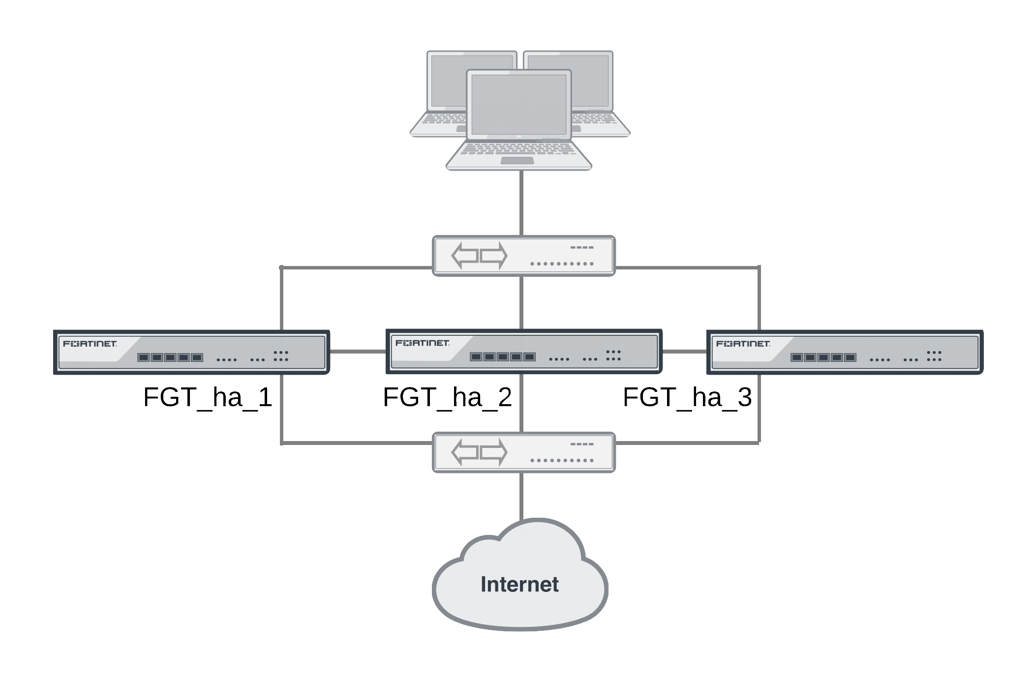
Example weighted load balancing configuration
Consider a cluster of three FortiGate units with host names FGT_ha_1, FGT_ha_2, and FGT_ha_3 as shown below. This example describes how to configure weighted load balancing settings for CPU and memory usage for the cluster and then to configure HTTP and POP3 proxy weights to send most HTTP and POP3 proxy sessions to different cluster units.
Example HA weighted load balancing configuration
Connect to the cluster CLI and use the following command to set the CPU usage threshold weight to 30, low watermark to 60, and high watermark to 80. This command also sets the memory usage threshold weight to 10, low watermark to 60, and high watermark to 90.
config system ha
set mode a-a
set schedule weight-round-robin
set cpu-threshold 30 60 80
set memory-threshold 10 60 90
end
The static weights for the cluster units remain at the default values of 40. Since this command changes the mode to a-a and the schedule to weight-round-robin for the first time, the weight settings are synchronized to all cluster units.
As a result of this configuration, if the CPU usage of any cluster unit (for example, FGT_ha_1) reaches 80% the static weight for that cluster unit is reduced from 40 to 10 and only 10 of every 120 new sessions are load balanced to this cluster unit. If the memory usage of FGT_ha_1 also reaches 90% the static weight further reduces to 0 and no new sessions are load balanced to FGT_ha_1. Also, if the memory usage of 620_ha_2 reaches 90% the static weight of FGT_ha_2 reduces to 30 and 30 of every 120 new sessions are load balanced to FGT_ha_2.
Now that you have established the weight load balancing configuration for the entire cluster you can monitor the cluster to verify that processing gets distributed evenly to all cluster units. From the web-based manager you can go do System > Config > HA > View HA Statistics and see the CPU usage, active sessions, memory usage and other statistics for all of the cluster units. If you notice that one cluster unit is more or less busy than others you can adjust the dynamic weights separately for each cluster unit.
For example, in some active-active clusters the primary unit may tend to be busier than other cluster units because in addition to processing sessions the primary unit also receives all packets sent to the cluster and performs load balancing to distribute the sessions to other cluster units. To reduce the load on the primary unit you could reduce the CPU and memory usage high watermark thresholds for the primary unit so that fewer sessions are distributed to the primary unit. You could also reduce the primary unit’s high watermark setting for the proxies to distribute more proxy sessions to other cluster units.
|
|
This would only be useful if you are using device priorities and override settings to make sure the same unit always becomes the primary unit. See An introduction to the FGCP. |
If the example cluster is configured for FGT_ha_2 to be the primary unit, connect to the FGT_ha_2’s CLI and enter the following command to set CPU usage, memory usage, and proxy usage high watermark thresholds lower.
config system ha
set cpu-threshold 30 60 70
set memory-threshold 30 60 70
set http-proxy-threshold 30 60 70
set ftp-proxy-threshold 30 60 70
set imap-proxy-threshold 30 60 70
set nntp-proxy-threshold 30 60 70
set pop3-proxy-threshold 30 60 70
set smtp-proxy-threshold 30 60 70
end
As a result, when any of these factors reaches 70% on the primary unit, fewer sessions will be processed by the primary unit, preventing the number of sessions being processed from rising.
NAT/Route mode active-active cluster packet flow
This section describes an example of how packets are load balanced and how failover occurs in an active-active HA cluster running in NAT/Route mode. In the example, the NAT/Route mode cluster acts as the internet firewall for a client computer’s internal network. The client computer’s default route points at the IP address of the cluster internal interface. The client connects to a web server on the Internet. Internet routing routes packets from the cluster external interface to the web server, and from the web server to the cluster external interface.
In NAT/Route mode, eight MAC addresses are involved in active-active communication between the client and the web server when the primary unit load balances packets to the subordinate unit:
- Internal virtual MAC address (MAC_V_int) assigned to the primary unit internal interface,
- External virtual MAC address (MAC_V_ext) assigned to the primary unit external interface,
- Client MAC address (MAC_Client),
- Server MAC address (MAC_Server),
- Primary unit original internal MAC address (MAC_P_int),
- Primary unit original external MAC address (MAC_P_ext),
- Subordinate unit internal MAC address (MAC_S_int),
- Subordinate unit external MAC address (MAC_S_ext).
In NAT/Route mode, the HA cluster works as a gateway when it responds to ARP requests. Therefore, the client and server only know the gateway MAC addresses. The client only knows the cluster internal virtual MAC address (MAC_V_int) and the server only knows the cluster external virtual MAC address (MAC_V_ext).
NAT/Route mode active-active packet flow
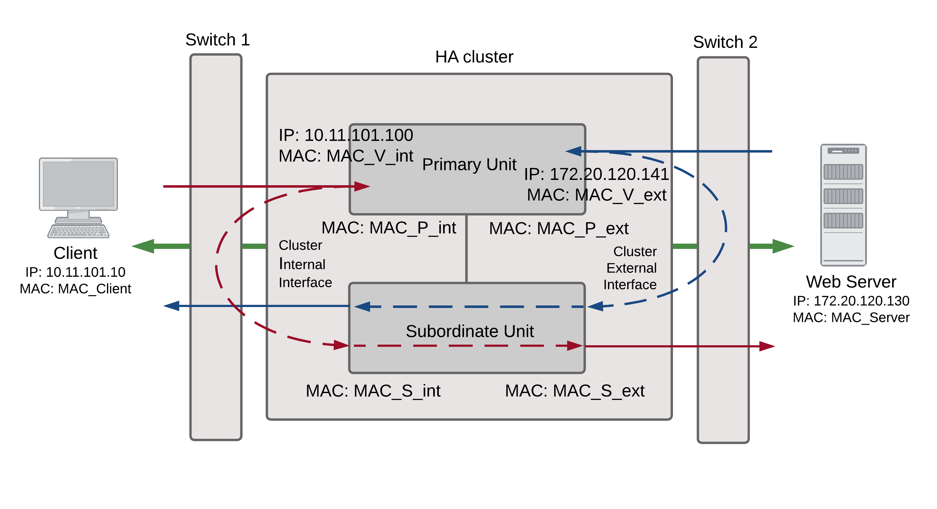
Packet flow from client to web server
- The client computer requests a connection from 10.11.101.10 to 172.20.120.130.
- The default route on the client computer recognizes 10.11.101.100 (the cluster IP address) as the gateway to the external network where the web server is located.
- The client computer issues an ARP request to 10.11.101.100.
- The primary unit intercepts the ARP request, and responds with the internal virtual MAC address (MAC_V_int) which corresponds to its IP address of 10.11.101.100.
- The client’s request packet reaches the primary unit internal interface.
| IP address | MAC address | |
| Source | 10.11.101.10 | MAC_Client |
| Destination | 172.20.120.130 | MAC_V_int |
- The primary unit decides that the subordinate unit should handle this packet, and forwards it to the subordinate unit internal interface. The source MAC address of the forwarded packet is changed to the actual MAC address of the primary unit internal interface.
| IP address | MAC address | |
| Source | 10.11.101.10 | MAC_P_int |
| Destination | 172.20.120.130 | MAC_S_int |
- The subordinate unit recognizes that the packet has been forwarded from the primary unit and processes it.
- The subordinate unit forwards the packet from its external interface to the web server.
| IP address | MAC address | |
| Source | 172.20.120.141 | MAC_S_ext |
| Destination | 172.20.120.130 | MAC_Server |
- The primary unit forwards further packets in the same session to the subordinate unit.
- Packets for other sessions are load balanced by the primary unit and either sent to the subordinate unit or processed by the primary unit.
Packet flow from web server to client
- When the web server responds to the client’s packet, the cluster external interface IP address (172.20.120.141) is recognized as the gateway to the internal network.
- The web server issues an ARP request to 172.20.120.141.
- The primary unit intercepts the ARP request, and responds with the external virtual MAC address (MAC_V_ext) which corresponds its IP address of 172.20.120.141.
- The web server then sends response packets to the primary unit external interface.
| IP address | MAC address | |
| Source | 172.20.120.130 | MAC_Server |
| Destination | 172.20.120.141 | MAC_V_ext |
- The primary unit decides that the subordinate unit should handle this packet, and forwards it to the subordinate unit external interface. The source MAC address of the forwarded packet is changed to the actual MAC address of the primary unit external interface.
| IP address | MAC address | |
| Source | 172.20.120.130 | MAC_P_ext |
| Destination | 172.20.120.141 | MAC_S_ext |
- The subordinate unit recognizes that packet has been forwarded from the primary unit and processes it.
- The subordinate unit forwards the packet from its internal interface to the client.
| IP address | MAC address | |
| Source | 172.20.120.130 | MAC_S_int |
| Destination | 10.11.101.10 | MAC_Client |
- The primary unit forwards further packets in the same session to the subordinate unit.
- Packets for other sessions are load balanced by the primary unit and either sent to the subordinate unit or processed by the primary unit.
When a failover occurs
The following steps are followed after a device or link failure of the primary unit causes a failover.
- If the primary unit fails, the subordinate unit negotiates to become the primary unit.
- The new primary unit changes the MAC addresses of all of its interfaces to the HA virtual MAC addresses.
The new primary unit has the same IP addresses and MAC addresses as the failed primary unit.
- The new primary units sends gratuitous ARP packets to the 10.10.101.0 network to associate its internal IP address with the internal virtual MAC address.
- The new primary units sends gratuitous ARP packets to the 172.20.120.0 network to associate its external IP address with the external virtual MAC address.
- Traffic sent to the cluster is now received and processed by the new primary unit.
If there were more than two cluster units in the original cluster, the new primary unit would load balance packets to the remaining cluster members.
Transparent mode active-active cluster packet flow
This section describes an example of how packets are load balanced and how failover occurs in an active-active HA cluster running in Transparent mode. The cluster is installed on an internal network in front of a mail server and the client connects to the mail server through the Transparent mode cluster.
In Transparent mode, six MAC addresses are involved in active-active communication between a client and a server when the primary unit load balances packets to the subordinate unit:
- Client MAC address (MAC_Client),
- Server MAC address (MAC_Server),
- Primary unit original internal MAC address (MAC_P_int),
- Primary unit original external MAC address (MAC_P_ext),
- Subordinate unit internal MAC address (MAC_S_int),
- Subordinate unit external MAC address (MAC_S_ext).
The HA virtual MAC addresses are not directly involved in communicate between the client and the server. The client computer sends packets to the mail server and the mail server sends responses. In both cases the packets are intercepted and load balanced among cluster members.
The cluster’s presence on the network and its load balancing are transparent to the client and server computers. The primary unit sends gratuitous ARP packets to Switch 1 that associate all MAC addresses on the network segment connected to the cluster external interface with the external virtual MAC address. The primary unit also sends gratuitous ARP packets to Switch 2 that associate all MAC addresses on the network segment connected to the cluster internal interface with the internal virtual MAC address. In both cases, this results in the switches sending packets to the primary unit interfaces.
Transparent mode active-active packet flow
![]()
Packet flow from client to mail server
- The client computer requests a connection from 10.11.101.10 to 10.11.101.200.
- The client computer issues an ARP request to 10.11.101.200.
- The primary unit forwards the ARP request to the mail server.
- The mail server responds with its MAC address (MAC_Server) which corresponds to its IP address of 10.11.101.200. The primary unit returns the ARP response to the client computer.
- The client’s request packet reaches the primary unit internal interface.
| IP address | MAC address | |
| Source | 10.11.101.10 | MAC_Client |
| Destination | 10.11.101.200 | MAC_Server |
- The primary unit decides that the subordinate unit should handle this packet, and forwards it to the subordinate unit internal interface. The source MAC address of the forwarded packet is changed to the actual MAC address of the primary unit internal interface.
| IP address | MAC address | |
| Source | 10.11.101.10 | MAC_P_int |
| Destination | 10.11.101.200 | MAC_S_int |
- The subordinate unit recognizes that packet has been forwarded from the primary unit and processes it.
- The subordinate unit forwards the packet from its external interface to the mail server.
| IP address | MAC address | |
| Source | 10.11.101.10 | MAC_S_ext |
| Destination | 10.11.101.200 | MAC_Server |
- The primary unit forwards further packets in the same session to the subordinate unit.
- Packets for other sessions are load balanced by the primary unit and either sent to the subordinate unit or processed by the primary unit.
Packet flow from mail server to client
- To respond to the client computer, the mail server issues an ARP request to 10.11.101.10.
- The primary unit forwards the ARP request to the client computer.
- The client computer responds with its MAC address (MAC_Client) which corresponds to its IP address of 10.11.101.10. The primary unit returns the ARP response to the mail server.
- The mail server’s response packet reaches the primary unit external interface.
| IP address | MAC address | |
| Source | 10.11.101.200 | MAC_Server |
| Destination | 10.11.101.10 | MAC_Client |
- The primary unit decides that the subordinate unit should handle this packet, and forwards it to the subordinate unit external interface. The source MAC address of the forwarded packet is changed to the actual MAC address of the primary unit external interface.
| IP address | MAC address | |
| Source | 10.11.101.200 | MAC_P_ext |
| Destination | 10.11.101.10 | MAC_S_ext |
- The subordinate unit recognizes that packet has been forwarded from the primary unit and processes it.
- The subordinate unit forwards the packet from its internal interface to the client.
| IP address | MAC address | |
| Source | 10.11.101.200 | MAC_S_int |
| Destination | 10.11.101.10 | MAC_Client |
- The primary unit forwards further packets in the same session to the subordinate unit.
- Packets for other sessions are load balanced by the primary unit and either sent to the subordinate unit or processed by the primary unit.
When a failover occurs
The following steps are followed after a device or link failure of the primary unit causes a failover.
- If the primary unit fails the subordinate unit negotiates to become the primary unit.
- The new primary unit changes the MAC addresses of all of its interfaces to the HA virtual MAC address.
- The new primary units sends gratuitous ARP requests to switch 1 to associate its MAC address with the MAC addresses on the network segment connected to the external interface.
- The new primary units sends gratuitous ARP requests to switch 2 to associate its MAC address with the MAC addresses on the network segment connected to the internal interface.
- Traffic sent to the cluster is now received and processed by the new primary unit.
If there were more than two cluster units in the original cluster, the new primary unit would load balance packets to the remaining cluster members.
Copyright © 2018 Fortinet, Inc. All Rights Reserved. | Terms of Service | Privacy Policy
