
How IS-IS works
As one of the original modern dynamic routing protocols, IS-IS is straightforward. Its routing algorithm is not complex, there are some options to allow fine tuning, and it is straightforward to configure IS-IS on FortiGate units.
From RFC 1142:
The routing algorithm used by the Decision Process is a shortest path first (SPF) algorithm. Instances of the algorithm are run independently and concurrently by all intermediate systems in a routing domain. IntraDomain routing of a PDU occurs on a hop-by-hop basis: that is, the algorithm determines only the next hop, not the complete path, that a data PDU will take to reach its destination.
IS-IS versus static routing
IS-IS was one of the earliest dynamic routing protocols to work with IP addresses. As such, it is not as complex as more recent protocols. However, IS-IS is a big step forward from simple static routing.
While IS-IS may be slow in response to network outages, static routing has zero response. The same is true for convergence—static routing has zero convergence. Both IS-IS and static routing have the limited hop count, so it is neither a strength nor a weakness.
TLV
IS-IS uses type-length-variable (TLV) parameters to carry information in Link-State PDUs (LSPs). Each IS-IS LSP consists of a variable-length header to which TLVs are appended in order to extend IS-IS for IP routing. The TLV field consists of one octet of type (T), one octet of length (L), and “L” octets of Value (V). They are included in all of the IS-IS Packet types. For a complete breakdown of the LSP, see LSP structure.
In IS-IS, TLVs are used to determine route-leaking and authentication, and are also used for IPv4 and IPv6 awareness and reachability.
- To determine which TLVs are responsible for route-leaking, see Default routing.
- To determine which TLVs are responsible for authentication, see Authentication.
For a complete list of reserved TLV codepoints, refer to RFC 3359.
LSP structure
It is difficult to fully understand a routing protocol without knowing what information is carried in its packets. Knowing how routers exchange each type of information will help you better understand the IS-IS protocol and will allow you to configure your network more appropriatey.
This section provides information on the contents of the IS-IS LSP. LSPs describe the network topology and can include IP routes and checksums.
NSAP and NET
IS-IS routing protocol utilizes ISO network addressing to identify network interfaces. The addresses are known as Network Service Access Points (NSAPs). In general, IS-IS routers consist of only one NSAP, whereas IP addressing requires one IP address per interface.
In IS-IS, the NSAP address is translated into a Network Entity Title (NET), which is the same as the NSAP but can differentiate end systems by way of a byte called the n-selector (NSEL). In order for adjacencies to form in IS-IS, the NSEL must necessarily be set to zero, to indicate “this system”. The total NET can be anywhere between 8 and 20 bytes long due to the support for variable length area addressing.
The following diagram identifies the individual parts of the NSAP, with explanations below.
NSAP and NET example
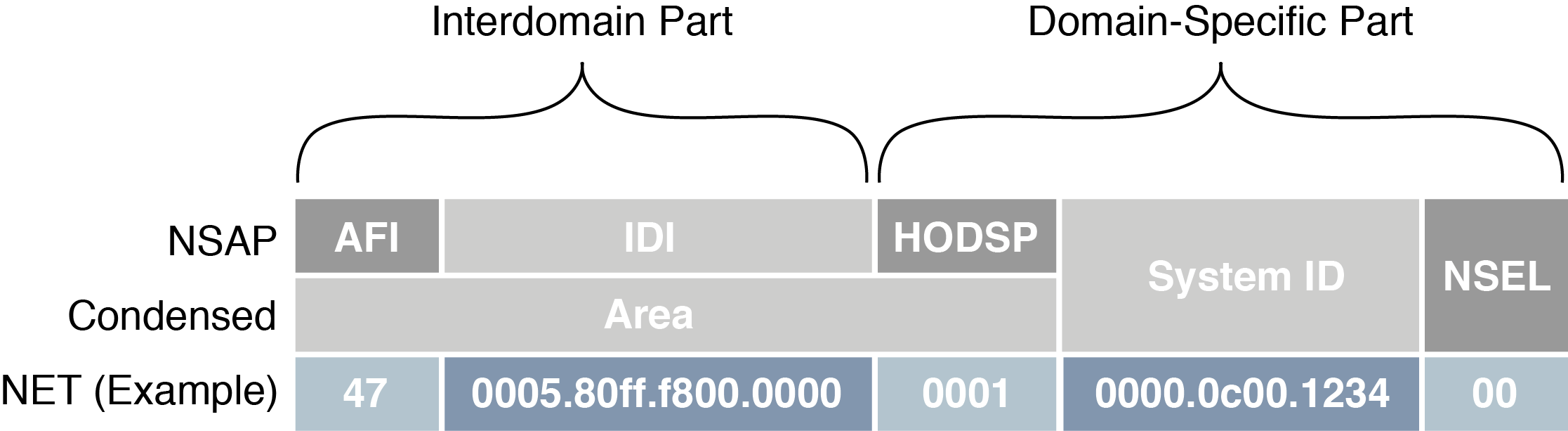
AFI — The Authority and Format Identifier (AFI) specifies the format of the addressing family used. IS-IS is designed to carry routing information for several different protocols. Each entry has an address family identifier that identifies the globally unique Interdomain Part (IDP). For example, 49 is the AFI for private addresses, whereas 47 is the AFI for international organizations.
IDI — The Initial Domain Identifier (IDI) identifies the routing domain within an interconnected network. The length of the IDI is typically determined by the AFI. If you are using an AFI of 49, you do not need to specify an IDI, since the network is private.
HODSP — The High Order Domain-Specific Part (HODSP) identifies the unique address within a specific routing domain. Together, the AFI, IDI, and HODSP define the area address. All of the nodes within an area must have the same area address.
System ID — The System ID represents the 6-8 byte router identifier. The ID could be Media Access Control (MAC) format, as in the example above, or a static length IP address expressed in binary-coded decimal (BCD) format.
NSEL — The n-selector (NSEL), as previously described, identifies the network layer transport service and must always be set to zero for IS-IS NETs.
Parts and terminology of IS-IS
Before you can understand how IS-IS functions, you need to understand some of the main concepts and parts of IS-IS.
This section includes:
DIS election and pseudonode LSP
In IS-IS routing protocol, a single router is chosen to be the designated intermediate system (DIS). The election of the DIS is determined automatically and dynamically on the LAN depending on highest interface priority and the subnetwork point of attachment (SNPA). The FortiGate is typically the DIS, and each router in its LAN is an intermediate system (IS).
Unlike OSPF, which elects a designated router (DR) and backup designated router (BDR), the DIS has no backup and determines the election of a new DIS whenever a router is added to the LAN or whenever the current DIS drops. A backup DIS is irrelevant since all of the routers on an IS-IS system are synchronized, and the short Hello interval used by the DIS quickly detects failures and the subsequent replacement of the DIS.
Synchronization of all the nodes in an IS-IS area could prove troublesome when updating the network infrastructure, and would demand ever-increasing resources each time a new router is added (at an exponential scale). For this purpose the DIS creates a pseudonode, which is essentially a virtual, logical node representing the LAN. The pseudonode requests adjacency status from all the routers in a multi-access network by sending IS-IS Hello (IIH) PDUs to Level 1 and Level 2 routers (where Level 1 routers share the same address as the DIS and Level 2 routers do not). Using a pseudonode to alter the representation of the LAN in the link-state database (LSD) greatly reduces the amount of adjacencies that area routers have to report. In essence, a pseudonode collapses a LAN topology, which allows a more linear scale to link-state advertising.
In order to maintain the database synchronization, the DIS periodically sends complete sequence number packets (CSNPs) to all participating routers.
Packet types
Four general packet types (PDUs) are communicated through IS-IS, appearing at both Level 1 and Level 2. They are described below.
Intermediate System-to-Intermediate System Hello (IIH) PDU — As mentioned previously, the IIH PDU, or Hello packet, detects neighboring routers and indicates to the pseudonode the area’s adjacency mesh. The Hello packet, flooded to the multicast address, contains the system ID of the sending router, the holding time, the circuit type of the interface on which the PDU was sent, the PDU length, the DIS identifier, and the interface priority (used in DIS election). The Hello packet also informs its area routers that it is the DIS.
Hello packets are padded to the maximum IS-IS PDU size of 1492 bytes (the full MTU size) to assist in the detection of transmission errors with large frames or with MTU mismatches between adjacencies.
The DIS typically floods Hello packets to the entire LAN every three seconds.
Link-state PDU (LSP) — The LSP contains information about each router in an area and its connected interfaces. LSPs are refreshed periodically and acknowledged on the network by way of sequence number PDUs. If new LSP information is found, based on the most recent complete sequence number PDU (CSNP), then out-of-date entries in the link-state database (LSDB) are removed and the LSDB is updated.
For a more detailed breakdown of the LSP, see LSP structure.
Complete sequence number PDU (CSNP) — CSNPs contain a list of all LSPs in the current LSDB. The CSNP informs other area routers of missing or outdated links in the adjacency mesh. The receiving routers then use this information to update their own database to ensure that all area routers converge.
In contrast to Hello packets, CSNPs are sent every ten seconds and only between neighbors. In other words, they are never flooded.
Partial sequence number PDU (PSNP) — PSNPs are used to request and acknowledge LSP information from an adjacency. When a router compares a CSNP with its local database and determines a discrepancy, the router requests an updated LSP using a PSNP. Once received, the router stores the LSP in its local database and responds to the DIS with acknowledgement.
Default routing
The default route is used if either there are no other routes in the routing table or if none of the other routes apply to a destination. Including the gateway in the default route gives all traffic a next-hop address to use when leaving the local network. The gateway address is normally another router on the edge of the local network.
FortiGate units come with a default static route with an IPv4 address of 0.0.0.0, an administration distance of 10, and a gateway IPv4 address. Beginner administrators can use the default route settings until a more advanced configuration is warranted.
By default, all routes are displayed in the Routing Monitor list. To display the routes in the routing table, go to Router > Monitor > Routing Monitor.
Route leaking
Route leaking is the term used to describe the bi-directional flow of information between internal and external routing interfaces. By default, IS-IS leaks routing information from a Level 1 area into a Level 2 area. In order to leak Level 2 routing information into a Level 1 area, you must configure an export policy. Whether or not a route is leaked is determined by the ATT bit, using TLV 128 (for internal IP reachability) and TLV 130 (for external IP address information). For more information on TLVs, see Troubleshooting IS-IS.
To configure IS-IS route leaking, use the following CLI commands.
- On a Level 1-2 router:
config router isis
set redistribute-l2 enable
end
- On a Level 1 router:
config router isis
get router info routing-table isis
get router info isis route
end
Default information originate option
Enabling default-information-originate generates and advertises a default route into the FortiGate unit’s IS-IS-enabled networks. The generated route may be based on routes learned through a dynamic routing protocol, routes in the routing table, or both. IS-IS does not create the default route unless you use the always option.
Select Disable if you experience any issues or if you wish to advertise your own static routes into IS-IS updates.
The CLI commands associated with default information originate include:
config router isis
set default-originate
end
Timer options
IS-IS uses various timers to regulate its performance including a garbage timer, update timer, and timeout timer. The FortiGate unit default timer settings (30, 180, and 120 seconds respectively) are effective in most configurations—if you change these settings, ensure that the new settings are compatible with local routers and access servers.
You can configure the three IS-IS timers in the CLI, using the following commands:
config router isis
set garbage-timer
set update-timer
set timeout-timer
end
You will find more information on each timer below.
Update timer
The update timer determines the interval between routing updates. Generally, this value is set to 30 seconds. There is some randomness added to help prevent network traffic congestion, which could result from all routers simultaneously attempting to update their neighbors. The update timer should be at least three times smaller than the timeout timer, otherwise you will experience an error.
If you are experiencing significant traffic on your network, you can increase this interval to send fewer updates per minute. However, ensure you increase the interval for all the routers on your network or you will experience timeouts that will degrade your network speed.
Timeout timer
The timeout timer is the maximum amount of time (in seconds) that a route is considered reachable while no updates are received for the route. This is the maximum time the DIS will keep a reachable route in the routing table while no updates for that route are received. If the DIS receives an update for the route before the timeout period expires, the timer is restarted. The timeout period should be at least three times longer than the update period, otherwise you will experience an error.
If you are experiencing problems with routers not responding in time to updates, increase this timer. However, remember that longer timeout intervals result in longer overall update periods — it may be considerable time before the DIS is done waiting for all the timers to expire on unresponsive routes.
Garbage timer
The garbage timer is the amount of time (in seconds) that the DIS will advertise a route as being unreachable before deleting the route from the routing table. If this timer is shorter, it will keep more up-to-date routes in the routing table and remove old ones faster. This results in a smaller routing table which is useful if you have a very large network, or if your network changes frequently.
Authentication
In routing protocols, it is typically desireable to establish authentication rules that prevent malicious and otherwise unwanted information from being injected into the routing table. IS-IS routing protocol utilizes TLV 10 to establish authentication. For more information on TLVs, see TLV.
Initially, IS-IS used plain Clear Text to navigate the authentication rules, but this was found to be insecure since the Clear Text packets were unencrypted and could be exposed to packet sniffers. As per RFC 3567, HMAC-MD5 and Enhanced Clear Text authentication features were introduced to IS-IS, both of which encrypt authentication data, making them considerably more secure than using plain Clear Text authentication.
HMAC-MD5 authentication
Hashed Message Authentication Codes - Message Digest 5 (HMAC-MD5) is a mechanism for applying a cryptographic hash function to the message authentication process. It is applied at both Level 1 and Level 2 routing. In IS-IS, an HMAC-MD5 can be applied to each type of LSP, on different interfaces, and with different passwords.
Authentication data is hashed using an AH (Authentication Header) key. From RFC 2085:
The “AH Key” is used as a shared secret between two communicating parties. The Key is not a “cryptographic key” as used in a traditional sense. Instead, the AH key (shared secret) is hashed with the transmitted data and thus, assures that an intervening party cannot duplicate the authentication data. [...] Implementation should, and as frequently as possible, change the AH key. Keys need to be chosen at random, or generated using a cryptographically strong pseudo-random generator seeded with a random seed.”
Clear Text authentication uses the configuration commands area-password and domain-password for authentication, but when migrating from Clear Text authentication to HMAC-MD5, these command settings are automatically overwritten.
By the year 2005, the MD5 hash function had been identified as vulnerable to collision search attacks and various weaknesses. While such vulnerabilities do not compromise the use of MD5 within HMAC, administrators need to be aware of potential developments in cryptanalysis and cryptographic hash functions in the likely event that the underlying hash function needs to be replaced.
Enhanced Clear Text authentication
Enhanced Clear Text authentication is an extension to Clear Text authentication that allows the encryption of passwords as they are displayed in the configuration. It includes a series of authentication mode commands and an authentican key chain, and allows for more simple password modification and password management. Enhanced Clear Text authentication also provides for smoother migration to and from changing authentication types. Intermediate systems continue to use the original authentication method until all the area routers are updated to use the new method.
Authentication key chain
A key chain is a list of one or more authentication keys including the send and receive lifetimes for each key. Keys are used for authenticating routing packets only during the specified lifetimes. A router migrates from one key to the next according to the scheduled send and receive lifetimes. If an active key is unavailable, then the PDU is automatically discarded.
From RFC 5310:
It should be noted that the cryptographic strength of the HMAC depends upon the cryptographic strength of the underlying hash function and on the size and quality of the key.
Troubleshooting IS-IS
This section includes:
Routing loops
Normally in routing, a path between two addresses is chosen and traffic is routed along that path from one address to the other. When there is a routing loop, that normal path doubles back on itself creating a loop. When there are loops, the network has problems.
A routing loop happens when a normally functioning network has an outage, and one or more routers are offline. When packets encounter this, an alternate route is attempted to maneuver around the outage. During this phase it is possible for a route to be attempted that involves going back a hop, and trying a different hop forward. If that hop forward is blocked by the outage as well, a hop back and possibly the original hop forward may be selected. You can see if this continues, how it can consume not only network bandwidth but also many resources on those routers affected. The worst part is this situation will continue until the network administrator changes the router settings, or the downed routers come back online.
Routing loop effect on the network
In addition to this “traffic jam” of routed packets, every time the routing table for a router changes that router sends an update out to all of the IS-IS routers connected to it. In a network loop, its possible for a router to change its routes very quickly as it tries and fails along these new routes. This can quickly result in a flood of updates being sent out, which can effectively grind the network to a halt until the problem is fixed.
How can you spot a routing loop
Any time network traffic slows down, you will be asking yourself if it is a network loop or not. Often slowdowns are normal, they are not a full stoppage, and normal traffic resumes in a short period of time.
If the slow down is a full halt of traffic or a major slowdown does not return to normal quickly, you need to do serious troubleshooting quickly.
Some methods to troubleshoot your outage include:
- Checking your logs
- Using SNMP network monitoring
- Using Link Health Monitor and e-mail alerts
- Looking at the packet flow
If you aren’t running SNMP, dead gateway detection, or you have non-Fortinet routers in your network, you can use networking tools such as ping and traceroute to define the outage on your network and begin to fix it.
Checking your logs
If your routers log events to a central location, it can be easy to check the logs for your network for any outages.
On your FortiGate unit, go to Log & Report > Log & Archive Access. You will want to look at both event logs and traffic logs. Events to look for will generally fall under CPU and memory usage, interfaces going offline (due to dead gateway detection), and other similar system events.
Once you have found and fixed your network problem, you can go back to the logs and create a report to better see how things developed during the problem. This type of forensics analysis can better help you prepare for next time.
Using SNMP network monitoring
If your network had no problems one minute and slows to a halt the next, chances are something changed to cause that problem. Most of the time an offline router is the cause, and once you find that router and bring it back online, things will return to normal.
If you can enable a hardware monitoring system such as SNMP or sFlow on your routers, you can be notified of the outage and where it is exactly as soon as it happens.
Ideally you can configure SNMP on all your FortiGate routers and be alerted to all outages as they occur.
To use SNMP to detect potential routing loops
- Go to System > Config > SNMP.
- Enable SNMP Agent.
- Optionally enter the Description, Location, and Contact information for this device for easier location of the problem report.
- In either SNMP v1/v2c section or SNMP v3 section, as appropriate, select Create New.
- Enter the Community Name that you want to use.
- In Hosts, select Add to add an IP address where you will be monitoring the FortiGate unit. You can add up to 8 different addresses.
- Ensure that ports 161 and 162 (SNMP queries and traps) are allowed through your security policies.
- In SNMP Event, select the events you want to be notified of. For routing loops this should include CPU Overusage, Memory Low, and possibly Log disk space low. If there are problems, the log will be filling up quickly, and the FortiGate unit’s resources will be overused.
- Select OK.
- Configure SNMP host (manager) software on your administration computer. This will monitor the SNMP information sent out by the FortiGate unit. Typically you can configure this software to alert you to outages or CPU spikes that may indicate a routing loop.
Using Link Health Monitor and e-mail alerts
Another tool available to you on FortiGate units is the Link Health Monitor, useful for dead gateway detection. This feature allows the FortiGate unit to ping a gateway at regular intervals to ensure it is online and working. When the gateway is not accessible, that interface is marked as down.
To detect possible routing loops with Link Health Monitor
- To configure dead gateway detection, go to Router > Static > Settings and select Create New.
- Set the Probe Interval (how often to send a ping), and Failure Threshold (how many lost pings is considered a failure). A smaller interval and smaller number of lost pings will result in faster detection, but will create more traffic on your network.
- You may also want to log CPU and Memory usage as a network outage will cause your CPU activity to spike.
|
|
If you have VDOMs configured, you will have to enter the basic SMTP server information in the Global section, and the rest of the configuration within the VDOM that includes this interface. |
After this configuration, when this interface on the FortiGate unit cannot connect to the next router, the FortiGate unit will bring down the interface and alert you with an email to the outage.
Looking at the packet flow
If you want to see what is happening on your network, look at the packets travelling on the network. In this situation, you are looking for routes that have metrics higher than 15 as that indicates they are unreachable. Ideally if you debug the flow of the packets, and record the routes that are unreachable, you can create an accurate picture of the network outage.
Action to take on discovering a routing loop
Once you have mapped the problem on your network, and determined it is in fact a routing loop there are a number of steps to take in correcting it.
- Get any offline routers back online. This may be a simple reboot, or you may have to replace hardware. Often this first step will restore your network to its normal operation, once the routing tables finish being updated.
- Change your routing configuration on the edges of the outage. Even if step 1 brought your network back online, you should consider making changes to improve your network before the next outage occurs. These changes can include configuring features like holddowns and triggers for updates, split horizon, and poison reverse updates.
Split horizon and Poison reverse updates
Split horizon is best explained with an example. You have three routers linked serially, let’s call them A, B, and C. A is only linked to B, C is only linked to B, and B is linked to both A and C. To get to C, A must go through B. If the link to C goes down, it is possible that B will try to use A’s route to get to C. This route is A-B-C, so it will not work. However, if B tries to use it this begins an endless loop.
This situation is called a split horizon because from B’s point of view the horizon stretches out in each direction, but in reality it only is on one side.
Poison reverse is the method used to prevent routes from running into split horizon problems. Poison reverse “poisons” routes away from the destination that use the current router in their route to the destination. This “poisoned” route is marked as unreachable for routers that cannot use it. In IS-IS this means that route is marked with a distance of 16.
Copyright © 2018 Fortinet, Inc. All Rights Reserved. | Terms of Service | Privacy Policy
