
VLANs
Virtual Local Area Networks (VLANs) multiply the capabilities of your FortiGate unit, and can also provide added network security. Virtual LANs (VLANs) use ID tags to logically separate devices on a network into smaller broadcast domains. These smaller domains forward packets only to devices that are part of that VLAN domain. This reduces traffic and increases network security.
A Local Area Network (LAN) is a group of connected computers and devices that are arranged into network broadcast domains. A LAN broadcast domain includes all the computers that receive a packet broadcast from any computer in that broadcast domain. A switch will automatically forward the packets to all of its ports; in contrast, routers do not automatically forward network broadcast packets. This means routers separate broadcast domains. If a network has only switches and no routers, that network is considered one broadcast domain, no matter how large or small it is. Smaller broadcast domains are more efficient because fewer devices receive unnecessary packets. They are more secure as well because a hacker reading traffic on the network will have access to only a small portion of the network instead of the entire network’s traffic.
Virtual LANs (VLANs) use ID tags to logically separate a LAN into smaller broadcast domains. Each VLAN is its own broadcast domain. Smaller broadcast domains reduce traffic and increase network security. The IEEE 802.1Q standard defines VLANs. All layer‑2 and layer-3 devices along a route must be 802.1Q-compliant to support VLANs along that route.
VLANs reduce the size of the broadcast domains by only forwarding packets to interfaces that are part of that VLAN or part of a VLAN trunk link. Trunk links form switch-to-switch or switch-to-router connections, and forward traffic for all VLANs. This enables a VLAN to include devices that are part of the same broadcast domain, but physically distant from each other.
VLAN ID tags consist of a 4-byte frame extension that switches and routers apply to every packet sent and received in the VLAN. Workstations and desktop computers, which are commonly originators or destinations of network traffic, are not an active part of the VLAN process. All the VLAN tagging and tag removal is done after the packet has left the computer.
Any FortiGate unit without VDOMs enabled can have a maximum of 255 interfaces in transparent operating mode. The same is true for any single VDOM. In NAT mode, the number can range from 255 to 8192 interfaces per VDOM, depending on the FortiGate model. These numbers include VLANs, other virtual interfaces, and physical interfaces. To have more than 255 interfaces configured in transparent operating mode, you need to configure multiple VDOMs that enable you to divide the total number of interfaces over all the VDOMs.
One example of an application of VLANs is a company’s accounting department. Accounting computers may be located at both main and branch offices. However, accounting computers need to communicate with each other frequently and require increased security. VLANs allow the accounting network traffic to be sent only to accounting computers and to connect accounting computers in different locations as if they were on the same physical subnet.
This guide uses the term “packet” to refer to both layer-2 frames and layer-3 packets.
VLAN ID rules
Layer-2 switches and layer-3 devices add VLAN ID tags to the traffic as it arrives and remove them before they deliver the traffic to its final destination. Devices such as PCs and servers on the network do not require any special configuration for VLANs. Twelve bits of the 4-byte VLAN tag are reserved for the VLAN ID number. Valid VLAN ID numbers are from 1 to 4094, while 0 is used for high priority frames, and 4095 is reserved.
On a layer-2 switch, you can have only one VLAN subinterface per physical interface, unless that interface is configured as a trunk link. Trunk links can transport traffic for multiple VLANs to other parts of the network.
On a FortiGate unit, you can add multiple VLANs to the same physical interface. However, VLAN subinterfaces added to the same physical interface cannot have the same VLAN ID or have IP addresses on the same subnet. You can add VLAN subinterfaces with the same VLAN ID to different physical interfaces.
Creating VLAN subinterfaces with the same VLAN ID does not create any internal connection between them. For example a VLAN ID of 300 on port1 and VLAN ID of 300 on port2 are allowed, but they are not connected. Their relationship is the same as between any two FortiGate network interfaces.
VLAN switching and routing
VLAN switching takes place on the OSI model layer-2, just like other network switching. VLAN routing takes place on the OSI model layer-3. The difference between them is that during VLAN switching, VLAN packets are simply forwarded to their destination. This is different from VLAN routing where devices can open the VLAN packets and change their VLAN ID tags to route the packets to a new destination.
VLAN layer-2 switching
Ethernet switches are layer-2 devices, and generally are 802.1Q compliant. Layer 2 refers to the second layer of the seven layer Open Systems Interconnect (OSI) basic networking model; the Data Link layer. FortiGate units act as layer-2 switches or bridges when they are in transparent mode. The units simply tag and forward the VLAN traffic or receive and remove the tags from the packets. A layer-2 device does not inspect incoming packets or change their contents; it only adds or removes tags and routes the packet.
A VLAN can have any number of physical interfaces assigned to it. Multiple VLANs can be assigned to the same physical interface. Typically two or more physical interfaces are assigned to a VLAN, one for incoming and one for outgoing traffic. Multiple VLANs can be configured on one FortiGate unit, including trunk links.
Layer-2 VLAN example
To better understand VLAN operation, this example shows what happens to a data frame on a network that uses VLANs.
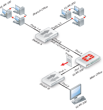
The network topology consists of two 8-port switches that are configured to support VLANs on a network. Both switches are connected through port 8 using an 802.1Q trunk link. Subnet 1 is connected to switch A, and subnet 2 is connected to switch B. The ports on the switches are configured as follows.
How ports and VLANs are used on Switch A and Switch B
| Switch | Ports | VLAN |
|---|---|---|
| A | 1 - 4 | 100 |
| A | 5 - 7 | 200 |
| A & B | 8 | Trunk link |
| B | 4 - 5 | 100 |
| B | 6 | 200 |
In this example, switch A is connected to the Branch Office and switch B to the Main Office.
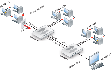
- A computer on port 1 of switch A sends a data frame over the network.
- Switch A tags the data frame with a VLAN 100 ID tag upon arrival because port 1 is part of VLAN 100.
- Switch A forwards the tagged data frame to the other VLAN 100 ports — ports 2 through 4. Switch A also forwards the data frame to the 802.1Q trunk link (port 8) so other parts of the network that may contain VLAN 100 groups will receive VLAN 100 traffic.
This data frame is not forwarded to the other ports on switch A because they are not part of VLAN 100. This increases security and decreases network traffic.
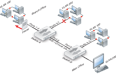
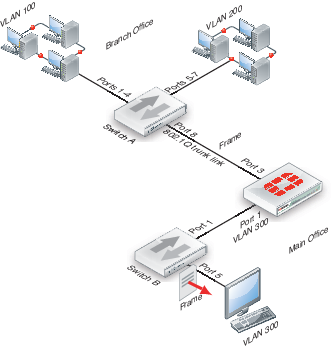
- Switch B receives the data frame over the trunk link (port 8).
- Because there are VLAN 100 ports on switch B (ports 4 and 5), the data frame is forwarded to those ports. As with switch A, the data frame is not delivered to VLAN 200.
If there were no VLAN 100 ports on switch B, the switch would not forward the data frame and it would stop there.

- The switch removes the VLAN 100 ID tag before it forwards the data frame to an end destination.
The sending and receiving computers are not aware of any VLAN tagging on the data frames that are being transmitted. When any computer receives that data frame, it appears as a normal data frame.
VLAN layer-3 routing
Routers are layer-3 devices. Layer 3 refers to the third layer of the OSI networking model, the Network layer. FortiGate units in NAT mode act as layer-3 devices. As with layer 2, FortiGate units acting as layer-3 devices are 802.1Q-compliant.
The main difference between layer-2 and layer-3 devices is how they process VLAN tags. Layer-2 switches just add, read and remove the tags. They do not alter the tags or do any other high-level actions. Layer-3 routers not only add, read and remove tags but also analyze the data frame and its contents. This analysis allows layer-3 routers to change the VLAN tag if it is appropriate and send the data frame out on a different VLAN.
In a layer-3 environment, the 802.1Q-compliant router receives the data frame and assigns a VLAN ID. The router then forwards the data frame to other members of the same VLAN broadcast domain. The broadcast domain can include local ports, layer-2 devices and layer-3 devices such as routers and firewalls. When a layer-3 device receives the data frame, the device removes the VLAN tag and examines its contents to decide what to do with the data frame. The layer-3 device considers:
- Source and destination addresses
- Protocol
- Port number
The data frame may be forwarded to another VLAN, sent to a regular non-VLAN-tagged network or just forwarded to the same VLAN as a layer-2 switch would do. Or, the data frame may be discarded if the proper security policy has been configured to do so.
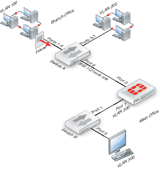
Layer-3 VLAN example
In this example, switch A is connected to the Branch Office subnet, the same as subnet 1 in the layer-2 example. In the Main Office subnet, VLAN 300 is on port 5 of switch B. The FortiGate unit is connected to switch B on port 1 and the trunk link connects the FortiGate unit’s port 3 to switch A. The other ports on switch B are unassigned.
This example explains how traffic can change VLANs originating on VLAN 100 and arriving at a destination on VLAN 300. Layer-2 switches alone cannot accomplish this, but a layer-3 router can.
- The VLAN 100 computer at the Branch Office sends the data frame to switch A, where the VLAN 100 tag is added.
- Switch A forwards the tagged data frame to the FortiGate unit over the 802.1Q trunk link, and to the VLAN 100 interfaces on Switch A.
Up to this point everything is the same as in the layer-2 example.
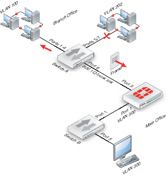
- The FortiGate unit removes the VLAN 100 tag, and inspects the content of the data frame. The FortiGate unit uses the content to select the correct security policy and routing options.
- The FortiGate unit’s security policy allows the data frame to go to VLAN 300 in this example. The data frame will be sent to all VLAN 300 interfaces, but in the example there is only port 1 on the FortiGate unit. Before the data frame leaves, the FortiGate unit adds the VLAN ID 300 tag to the data frame.
This is the step that layer 2 cannot do. Only layer 3 can retag a data frame as a different VLAN.
- Switch B receives the data frame, and removes the VLAN ID 300 tag, because this is the last hop, and forwards the data frame to the computer on port 5.
In this example, a data frame arrived at the FortiGate unit tagged as VLAN 100. After checking its content, the FortiGate unit retagged the data frame for VLAN 300. It is this change from VLAN 100 to VLAN 300 that requires a layer-3 routing device, in this case the FortiGate unit. Layer-2 switches cannot perform this change.
VLANs in NAT mode
In NAT mode the FortiGate unit functions as a layer-3 device. In this mode, the FortiGate unit controls the flow of packets between VLANs, but can also remove VLAN tags from incoming VLAN packets. The FortiGate unit can also forward untagged packets to other networks, such as the Internet.
In NAT mode, the FortiGate unit supports VLAN trunk links with IEEE 802.1Q‑compliant switches, or routers. The trunk link transports VLAN-tagged packets between physical subnets or networks. When you add VLAN sub-interfaces to the FortiGate unit physical interfaces, the VLANs have IDs that match the VLAN IDs of packets on the trunk link. The FortiGate unit directs packets with VLAN IDs to sub‑interfaces with matching IDs.
You can define VLAN sub-interfaces on all FortiGate physical interfaces. However, if multiple virtual domains are configured on the FortiGate unit, you will have access to only the physical interfaces on your virtual domain. The FortiGate unit can tag packets leaving on a VLAN subinterface. It can also remove VLAN tags from incoming packets and add a different VLAN tag to outgoing packets.
Normally in VLAN configurations, the FortiGate unit's internal interface is connected to a VLAN trunk, and the external interface connects to an Internet router that is not configured for VLANs. In this configuration the FortiGate unit can apply different policies for traffic on each VLAN interface connected to the internal interface, which results in less network traffic and better security.
Adding VLAN subinterfaces
A VLAN subinterface, also called a VLAN, is a virtual interface on a physical interface. The subinterface allows routing of VLAN tagged packets using that physical interface, but it is separate from any other traffic on the physical interface.
Adding a VLAN subinterface includes configuring:
- Physical interface
- IP address and netmask
- VLAN ID
- VDOM
Physical interface
The term VLAN subinterface correctly implies the VLAN interface is not a complete interface by itself. You add a VLAN subinterface to the physical interface that receives VLAN-tagged packets. The physical interface can belong to a different VDOM than the VLAN, but it must be connected to a network router that is configured for this VLAN. Without that router, the VLAN will not be connected to the network, and VLAN traffic will not be able to access this interface. The traffic on the VLAN is separate from any other traffic on the physical interface.
When you are working with interfaces on your FortiGate unit, use the Column Settings on the Interface display to make sure the information you need is displayed. When working with VLANs, it is useful to position the VLAN ID column close to the IP address. If you are working with VDOMs, including the Virtual Domain column as well will help you troubleshoot problems more quickly.
To view the Interface display, go to System > Network > Interface.
IP address and netmask
FortiGate unit interfaces cannot have overlapping IP addresses. The IP addresses of all interfaces must be on different subnets. This rule applies to both physical interfaces and to virtual interfaces such as VLAN subinterfaces. Each VLAN subinterface must be configured with its own IP address and netmask pair. This rule helps prevent a broadcast storm or other similar network problems.
|
|
If you are unable to change your existing configurations to prevent IP overlap, enter the CLI command config system settings and set allow-subnet-overlap enable to allow IP address overlap. If you enter this command, multiple VLAN interfaces can have an IP address that is part of a subnet used by another interface. This command is recommended for advanced users only. |
VLAN ID
The VLAN ID is part of the VLAN tag added to the packets by VLAN switches and routers. The VLAN ID is a number between 1 and 4094 that allow groups of IP addresses with the same VLAN ID to be associated together. VLAN ID 0 is used only for high priority frames, and 4095 is reserved.
All devices along a route must support the VLAN ID of the traffic along that route. Otherwise, the traffic will be discarded before reaching its destination. For example, if your computer is part of VLAN_100 and a co-worker on a different floor of your building is also on the same VLAN_100, you can communicate with each other over VLAN_100, only if all the switches and routers support VLANs and are configured to pass along VLAN_100 traffic properly. Otherwise, any traffic you send your co-worker will be blocked or not delivered.
VDOM
If VDOMs are enabled, each VLAN subinterface must belong to a VDOM. This rule also applies for physical interfaces.
|
|
Interface-related CLI commands require a VDOM to be specified, regardless of whether the FortiGate unit has VDOMs enabled. |
VLAN subinterfaces on separate VDOMs cannot communicate directly with each other. In this situation, the VLAN traffic must exit the FortiGate unit and re-enter the unit again, passing through firewalls in both directions. This situation is the same for physical interfaces.
A VLAN subinterface can belong to a different VDOM than the physical interface it is part of. This is because the traffic on the VLAN is handled separately from the other traffic on that interface. This is one of the main strengths of VLANs.
The following procedure will add a VLAN subinterface called VLAN_100 to the FortiGate internal interface with a VLAN ID of 100. It will have an IP address and netmask of 172.100.1.1/255.255.255.0, and allow HTTPS, PING, and Telnet administrative access. Note that in the CLI, you must enter “set type vlan” before setting the vlanid, and that the allowaccess protocols are lower case.
To add a VLAN subinterface in NAT mode - web-based manager
- If Current VDOM appears at the bottom left of the screen, select Global from the list of VDOMs.
- Go to System > Network > Interface.
- Select Create New to add a VLAN subinterface.
- Enter the following:
| VLAN Name | VLAN_100 |
| Type | VLAN |
| Interface | internal |
| VLAN ID | 100 |
| Addressing Mod | Manual |
| IP/Netmask | 172.100.1.1/255.255.255.0 |
| Administrative Access | HTTPS, PING, TELNET |
- Select OK.
To view the new VLAN subinterface, select the expand arrow next to the parent physical interface (the internal interface). This will expand the display to show all VLAN subinterfaces on this physical interface. If there is no expand arrow displayed, there are no subinterfaces configured on that physical interface.
For each VLAN, the list displays the name of the VLAN, and, depending on column settings, its IP address, the Administrative access you selected for it, the VLAN ID number, and which VDOM it belongs to if VDOMs are enabled.
To add a VLAN subinterface in NAT mode - CLI
config system interface
edit VLAN_100
set interface internal
set type vlan
set vlanid 100
set ip 172.100.1.1 255.255.255.0
set allowaccess https ping telnet
end
Configuring security policies and routing
Once you have created a VLAN subinterface on the FortiGate unit, you need to configure security policies and routing for that VLAN. Without these, the FortiGate unit will not pass VLAN traffic to its intended destination. Security policies direct traffic through the FortiGate unit between interfaces. Routing directs traffic across the network.
Configuring security policies
Security policies permit communication between the FortiGate unit’s network interfaces based on source and destination IP addresses. Interfaces that communicate with the VLAN interface need security policies to permit traffic to pass between them and the VLAN interface.
Each VLAN needs a security policy for each of the following connections the VLAN will be using:
- From this VLAN to an external network
- From an external network to this VLAN
- From this VLAN to another VLAN in the same virtual domain on the FortiGate unit
- From another VLAN to this VLAN in the same virtual domain on the FortiGate unit.
The packets on each VLAN are subject to antivirus scans and other UTM measures as they pass through the FortiGate unit.
Configuring routing
As a minimum, you need to configure a default static route to a gateway with access to an external network for outbound packets. In more complex cases, you will have to configure different static or dynamic routes based on packet source and destination addresses.
As with firewalls, you need to configure routes for VLAN traffic. VLANs need routing and a gateway configured to send and receive packets outside their local subnet just as physical interfaces do. The type of routing you configure, static or dynamic, will depend on the routing used by the subnet and interfaces you are connecting to. Dynamic routing can be routing information protocol (RIP), border gateway protocol (BGP), open shortest path first (OSPF), or multicast.
If you enable SSH, PING, Telnet, HTTPS and HTTP on the VLAN, you can use those protocols to troubleshoot your routing and test that it is properly configured. Enabling logging on the interfaces and using CLI diagnose commands such as diagnose sniff packet <interface_name> can also help locate any possible configuration or hardware issues.
Example VLAN configuration in NAT mode
In this example two different internal VLAN networks share one interface on the FortiGate unit, and share the connection to the Internet. This example shows that two networks can have separate traffic streams while sharing a single interface. This configuration could apply to two departments in a single company, or to different companies.
There are two different internal network VLANs in this example. VLAN_100 is on the 10.1.1.0/255.255.255.0 subnet, and VLAN_200 is on the 10.1.2.0/255.255.255.0 subnet. These VLANs are connected to the VLAN switch, such as a Cisco 2950 Catalyst switch.
The FortiGate internal interface connects to the VLAN switch through an 802.1Q trunk. The internal interface has an IP address of 192.168.110.126 and is configured with two VLAN subinterfaces (VLAN_100 and VLAN_200). The external interface has an IP address of 172.16.21.2 and connects to the Internet. The external interface has no VLAN subinterfaces.
FortiGate unit with VLANs in NAT mode
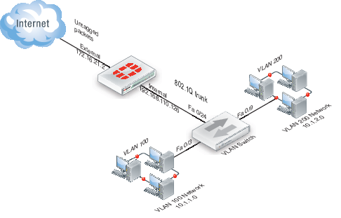
When the VLAN switch receives packets from VLAN_100 and VLAN_200, it applies VLAN ID tags and forwards the packets of each VLAN both to local ports and to the FortiGate unit across the trunk link. The FortiGate unit has policies that allow traffic to flow between the VLANs, and from the VLANs to the external network.
This section describes how to configure a FortiGate unit and a Cisco Catalyst 2950 switch for this example network topology. The Cisco configuration commands used in this section are IOS commands.
It is assumed that both the FortiGate unit and the Cisco 2950 switch are installed and connected and that basic configuration has been completed. On the switch, you will need to be able to access the CLI to enter commands. Refer to the manual for your FortiGate model as well as the manual for the switch you select for more information.
It is also assumed that no VDOMs are enabled.
General configuration steps
The following steps provide an overview of configuring and testing the hardware used in this example. For best results in this configuration, follow the procedures in the order given. Also, note that if you perform any additional actions between procedures, your configuration may have different results.
- Configure the FortiGate unit
- Configure the external interface
- Add two VLAN subinterfaces to the internal network interface
- Add firewall addresses and address ranges for the internal and external networks
- Add security policies to allow:
- the VLAN networks to access each other
- the VLAN networks to access the external network.
- Configure the VLAN switch
Configure the FortiGate unit
Configuring the FortiGate unit includes:
Configure the external interface
The FortiGate unit’s external interface will provide access to the Internet for all internal networks, including the two VLANs.
To configure the external interface - web-based manager
- Go to System > Network > Interface.
- Select Edit for the external interface.
- Enter the following information and select OK:
| Addressing mode | Manual |
| IP/Network Mask | 172.16.21.2/255.255.255.0 |
To configure the external interface - CLI
config system interface
edit external
set mode static
set ip 172.16.21.2 255.255.255.0
end
Add VLAN subinterfaces
This step creates the VLANs on the FortiGate unit internal physical interface. The IP address of the internal interface does not matter to us, as long as it does not overlap with the subnets of the VLAN subinterfaces we are configuring on it.
The rest of this example shows how to configure the VLAN behavior on the FortiGate unit, configure the switches to direct VLAN traffic the same as the FortiGate unit, and test that the configuration is correct.
Adding VLAN subinterfaces can be completed through the web-based manager, or the CLI.
To add VLAN subinterfaces - web-based manager
- Go to System > Network > Interface.
- Select Create New.
- Enter the following information and select OK:
| Name | VLAN_100 |
| Interface | internal |
| VLAN ID | 100 |
| Addressing mode | Manual |
| IP/Network Mask | 10.1.1.1/255.255.255.0 |
| Administrative Access | HTTPS, PING, TELNET |
- Select Create New.
- Enter the following information and select OK:
| Name | VLAN_200 |
| Interface | internal |
| VLAN ID | 200 |
| Addressing mode | Manual |
| IP/Network Mask | 10.1.2.1/255.255.255.0 |
| Administrative Access | HTTPS, PING, TELNET |
To add VLAN subinterfaces - CLI
config system interface
edit VLAN_100
set vdom root
set interface internal
set type vlan
set vlanid 100
set mode static
set ip 10.1.1.1 255.255.255.0
set allowaccess https ping telnet
next
edit VLAN_200
set vdom root
set interface internal
set type vlan
set vlanid 200
set mode static
set ip 10.1.2.1 255.255.255.0
set allowaccess https ping telnet
end
Add the firewall addresses
You need to define the addresses of the VLAN subnets for use in security policies. The FortiGate unit provides one default address, “all”, that you can use when a security policy applies to all addresses as a source or destination of a packet. However, using “all” is less secure and should be avoided when possible.
In this example, the “_Net” part of the address name indicates a range of addresses instead of a unique address. When choosing firewall address names, use informative and unique names.
To add the firewall addresses - web-based manager
- Go to Firewall Objects > Address > Addresses.
- Select Create New.
- Enter the following information and select OK:
| Name | VLAN_100_Net |
| Type | Subnet |
| Subnet / IP Range | 10.1.1.0/255.255.255.0 |
- Select Create New.
- Enter the following information and select OK:
| Name | VLAN_200_Net |
| Type | Subnet |
| Subnet / IP Range | 10.1.2.0/255.255.255.0 |
To add the firewall addresses - CLI
config firewall address
edit VLAN_100_Net
set type ipmask
set subnet 10.1.1.0 255.255.255.0
next
edit VLAN_200_Net
set type ipmask
set subnet 10.1.2.0 255.255.255.0
end
Add the security policies
Once you have assigned addresses to the VLANs, you need to configure security policies for them to allow valid packets to pass from one VLAN to another and to the Internet.
|
|
You can customize the Security Policy display by including some or all columns, and customize the column order onscreen. Due to this feature, security policy screenshots may not appear the same as on your screen. |
If you do not want to allow all services on a VLAN, you can create a security policy for each service you want to allow. This example allows all services.
To add the security policies - web-based manager
- Go to Policy & Objects > Policy > IPv4 or Policy & Objects > Policy > IPv6 and select Create New.
- Leave the Policy Type as Firewall and the Policy Subtype as Address.
- Enter the following information and select OK:
| Incoming Interface | VLAN_100 |
| Source Address | VLAN_100_Net |
| Outgoing Interface | VLAN_200 |
| Destination Address | VLAN_200_Net |
| Schedule | Always |
| Service | ALL |
| Action | ACCEPT |
| Enable NAT | Enable |
- Select Create New.
- Leave the Policy Type as Firewall and the Policy Subtype as Address.
- Enter the following information and select OK:
| Incoming Interface | VLAN_200 |
| Source Address | VLAN_200_Net |
| Outgoing Interface | VLAN_100 |
| Destination Address | VLAN_100_Net |
| Schedule | Always |
| Service | ALL |
| Action | ACCEPT |
| Enable NAT | Enable |
- Select Create New.
- Leave the Policy Type as Firewall and the Policy Subtype as Address.
- Enter the following information and select OK:
| Incoming Interface | VLAN_100 |
| Source Address | VLAN_100_Net |
| Outgoing Interface | external |
| Destination Address | all |
| Schedule | Always |
| Service | ALL |
| Action | ACCEPT |
| Enable NAT | Enable |
- Select Create New.
- Verify that the Policy Type is Firewall and the Policy Subtype is Address.
- Enter the following information and select OK:
| Incoming Interface | VLAN_200 |
| Source Address | VLAN_200_Net |
| Outgoing Interface | external |
| Destination Address | all |
| Schedule | Always |
| Service | ALL |
| Action | ACCEPT |
| Enable NAT | Enable |
To add the security policies - CLI
config firewall policy or Config firewall policy6
edit 1
set srcintf VLAN_100
set srcaddr VLAN_100_Net
set dstintf VLAN_200
set dstaddr VLAN_200_Net
set schedule always
set service ALL
set action accept
set nat enable
set status enable
next
edit 2
set srcintf VLAN_200
set srcaddr VLAN_200_Net
set dstintf VLAN_100
set dstaddr VLAN_100_Net
set schedule always
set service ALL
set action accept
set nat enable
set status enable
next
edit 3
set srcintf VLAN_100
set srcaddr VLAN_100_Net
set dstintf external
set dstaddr all
set schedule always
set service ALL
set action accept
set nat enable
set status enable
next
edit 4
set srcintf VLAN_200
set srcaddr VLAN_200_Net
set dstintf external
set dstaddr all
set schedule always
set service ALL
set action accept
set nat enable
set status enable
end
Configure the VLAN switch
On the Cisco Catalyst 2950 Catalyst VLAN switch, you need to define VLANs 100 and 200 in the VLAN database, and then add a configuration file to define the VLAN subinterfaces and the 802.1Q trunk interface.
One method to configure a Cisco switch is to connect over a serial connection to the console port on the switch, and enter the commands at the CLI. Another method is to designate one interface on the switch as the management interface and use a web browser to connect to the switch’s graphical interface. For details on connecting and configuring your Cisco switch, refer to the installation and configuration manuals for the switch.
The switch used in this example is a Cisco Catalyst 2950 switch. The commands used are IOS commands. Refer to the switch manual for help with these commands.
To configure the VLAN subinterfaces and the trunk interfaces
Add this file to the Cisco switch:
!
interface FastEthernet0/3
switchport access vlan 100
!
interface FastEthernet0/9
switchport access vlan 200
!
interface FastEthernet0/24
switchport trunk encapsulation dot1q
switchport mode trunk
!
The switch has the configuration:
| Port 0/3 | VLAN ID 100 |
| Port 0/9 | VLAN ID 200 |
| Port 0/24 | 802.1Q trunk |
|
|
To complete the setup, configure devices on VLAN_100 and VLAN_200 with default gateways. The default gateway for VLAN_100 is the FortiGate VLAN_100 subinterface. The default gateway for VLAN_200 is the FortiGate VLAN_200 subinterface. |
Test the configuration
Use diagnostic commands, such as tracert, to test traffic routed through the FortiGate unit and the Cisco switch.
Testing traffic from VLAN_100 to VLAN_200
In this example, a route is traced between the two internal networks. The route target is a host on VLAN_200.
Access a command prompt on a Windows computer on the VLAN_100 network, and enter the following command:
C:\>tracert 10.1.2.2
Tracing route to 10.1.2.2 over a maximum of 30 hops:
1 <10 ms <10 ms <10 ms 10.1.1.1
2 <10 ms <10 ms <10 ms 10.1.2.2
Trace complete.
Testing traffic from VLAN_200 to the external network
In this example, a route is traced from an internal network to the external network. The route target is the external network interface of the FortiGate-800 unit.
From VLAN_200, access a command prompt and enter this command:
C:\>tracert 172.16.21.2
Tracing route to 172.16.21.2 over a maximum of 30 hops:
1 <10 ms <10 ms <10 ms 10.1.2.1
2 <10 ms <10 ms <10 ms 172.16.21.2
Trace complete.
VLANs in transparent mode
In transparent mode, the FortiGate unit behaves like a layer-2 bridge but can still provide services such as antivirus scanning, web filtering, spam filtering and intrusion protection to traffic. There are some limitations in transparent mode in that you cannot use SSL VPN, PPTP/L2TP VPN, DHCP server, or easily perform NAT on traffic. The limits in transparent mode apply to IEEE 802.1Q VLAN trunks passing through the unit.
VLANs and transparent mode
You can insert the FortiGate unit operating in transparent mode into the VLAN trunk without making changes to your network. In a typical configuration, the FortiGate unit internal interface accepts VLAN packets on a VLAN trunk from a VLAN switch or router connected to internal network VLANs. The FortiGate external interface forwards VLAN‑tagged packets through another VLAN trunk to an external VLAN switch or router and on to external networks such as the Internet. You can configure the unit to apply different policies for traffic on each VLAN in the trunk.
To pass VLAN traffic through the FortiGate unit, you add two VLAN subinterfaces with the same VLAN ID, one to the internal interface and the other to the external interface. You then create a security policy to permit packets to flow from the internal VLAN interface to the external VLAN interface. If required, you create another security policy to permit packets to flow from the external VLAN interface to the internal VLAN interface. Typically in transparent mode, you do not permit packets to move between different VLANs. Network protection features, such as spam filtering, web filtering and anti-virus scanning, are applied through the UTM profiles specified in each security policy, enabling very detailed control over traffic.
When the FortiGate unit receives a VLAN-tagged packet at a physical interface, it directs the packet to the VLAN subinterface with the matching VLAN ID. The VLAN tag is removed from the packet, and the FortiGate unit then applies security policies using the same method it uses for non-VLAN packets. If the packet exits the FortiGate unit through a VLAN subinterface, the VLAN ID for that subinterface is added to the packet and the packet is sent to the corresponding physical interface.
There are two essential steps to configure your FortiGate unit to work with VLANs in transparent mode:
You can also configure the protection profiles that manage antivirus scanning, web filtering and spam filtering. For more information on UTM profiles, see the UTM Guide.
Add VLAN subinterfaces
The VLAN ID of each VLAN subinterface must match the VLAN ID added by the IEEE 802.1Q-compliant router or switch. The VLAN ID can be any number between 1 and 4094, with 0 being used only for high priority frames and 4095 being reserved. You add VLAN subinterfaces to the physical interface that receives VLAN-tagged packets.
For this example, we are creating a VLAN called internal_v225 on the internal interface, with a VLAN ID of 225. Administrative access is enabled for HTTPS and SSH. VDOMs are not enabled.
To add VLAN subinterfaces in transparent mode - web-based manager
- Go to System > Network > Interface.
- Select Create New.
- Enter the following information and select OK.
| Name | internal_v225 |
| Type | VLAN |
| Interface | internal |
| VLAN ID | 225 |
| Administrative Access | Enable HTTPS, and SSH. These are very secure access methods. |
| Comments | VLAN 225 on internal interface |
The FortiGate unit adds the new subinterface to the interface that you selected.
Repeat steps 2 and 3 to add additional VLANs. You will need to change the VLAN ID, Name, and possibly Interface when adding additional VLANs.
To add VLAN subinterfaces in transparent mode - CLI
config system interface
edit internal_v225
set interface internal
set vlanid 225
set allowaccess HTTPS SSH
set description “VLAN 225 on internal interface”
set vdom root
end
Create security policies
In transparent mode, the FortiGate unit performs antivirus and antispam scanning on each VLAN’s packets as they pass through the unit. You need security policies to permit packets to pass from the VLAN interface where they enter the unit to the VLAN interface where they exit the unit. If there are no security policies configured, no packets will be allowed to pass from one interface to another.
To add security policies for VLAN subinterfaces - web based manager
- Go to Policy & Objects > Objects > Addresses.
- Select Create New to add firewall addresses that match the source and destination IP addresses of VLAN packets.
- Go to Policy & Objects > Policy > IPv4 or Policy & Objects > Policy > IPv6 and select Create New.
- From the Incoming Interface/Zone list, select the VLAN interface where packets enter the unit.
- From the Outgoing Interface/Zone list, select the VLAN interface where packets exit the unit.
- Select the Source and Destination Address names that you added in step 2.
- Select OK.
To add security policies for VLAN subinterfaces - CLI
config firewall address
edit incoming_VLAN_address
set associated-interface <incoming_VLAN_interface>
set type ipmask
set subnet <IPv4_address_mask)
next
edit outgoing_VLAN_address
set associated-interface <outgoing_VLAN_interface>
set type ipmask
set subnet <IPv4_address_mask>
next
end
config firewall policy or config firewall policy6
edit <unused_policy_number>
set srcintf <incoming_VLAN_interface>
set srcaddr incoming_VLAN_address
set destintf <outgoing_VLAN_interface>
set destaddr outgoing_VLAN_address
set schedule always
set service <protocol_to_allow_on VLAN>
set action ACCEPT
next
end
Example of VLANs in transparent mode
In this example, the FortiGate unit is operating in transparent mode and is configured with two VLANs: one with an ID of 100 and the other with ID 200. The internal and external physical interfaces each have two VLAN subinterfaces, one for VLAN_100 and one for VLAN_200.
The IP range for the internal VLAN_100 network is 10.100.0.0/255.255.0.0, and for the internal VLAN_200 network is 10.200.0.0/255.255.0.0.
The internal networks are connected to a Cisco 2950 VLAN switch, which combines traffic from the two VLANs onto one in the FortiGate unit internal interface. The VLAN traffic leaves the FortiGate unit on the external network interface, goes on to the VLAN switch, and on to the Internet. When the FortiGate units receives a tagged packet, it directs it from the incoming VLAN subinterface to the outgoing VLAN subinterface for that VLAN.
This section describes how to configure a FortiGate-800 unit, Cisco switch, and Cisco router in the network topology shown below.
VLAN transparent network topology
![]()
General configuration steps
The following steps summarize the configuration for this example. For best results, follow the procedures in the order given. Also, note that if you perform any additional actions between procedures, your configuration may have different results.
- Configure the FortiGate unit which includes
- Adding VLAN subinterfaces
- Adding the security policies
- Configure the Cisco switch and router
Configure the FortiGate unit
The FortiGate unit must be configured with the VLAN subinterfaces and the proper security policies to enable traffic to flow through the FortiGate unit.
Add VLAN subinterfaces
For each VLAN, you need to create a VLAN subinterface on the internal interface and another one on the external interface, both with the same VLAN ID.
To add VLAN subinterfaces - web-based manager
- Go to System > Network > Interface.
- Select Create New.
- Enter the following information and select OK:
| Name | VLAN_100_int |
| Interface | internal |
| VLAN ID | 100 |
- Select Create New.
- Enter the following information and select OK:
| Name | VLAN_100_ext |
| Interface | external |
| VLAN ID | 100 |
- Select Create New.
- Enter the following information and select OK:
| Name | VLAN_200_int |
| Interface | internal |
| VLAN ID | 200 |
- Select Create New.
- Enter the following information and select OK:
| Name | VLAN_200_ext |
| Interface | external |
| VLAN ID | 200 |
To add VLAN subinterfaces - CLI
config system interface
edit VLAN_100_int
set status down
set type vlan
set interface internal
set vlanid 100
next
edit VLAN_100_ext
set status down
set type vlan
set interface external
set vlanid 100
next
edit VLAN_200_int
set status down
set type vlan
set interface internal
set vlanid 200
next
edit VLAN_200_ext
set status down
set type vlan
set interface external
set vlanid 200
end
Add the security policies
Security policies allow packets to travel between the VLAN_100_int interface and the VLAN_100_ext interface. Two policies are required; one for each direction of traffic. The same is required between the VLAN_200_int interface and the VLAN_200_ext interface, for a total of four required security policies.
To add the security policies - web-based manager
- Go to Policy & Objects > Policy > IPv4 or Policy & Objects > Policy > IPv6 and select Create New.
- Enter the following information and select OK:
| Incoming Interface | VLAN_100_int |
| Source Address | all |
| Outgoing Interface | VLAN_100_ext |
| Destination Address | all |
| Schedule | Always |
| Service | ALL |
| Action | ACCEPT |
- Select Create New.
- Enter the following information and select OK:
| Incoming Interface | VLAN_100_ext |
| Source Address | all |
| Outgoing Interface | VLAN_100_int |
| Destination Address | all |
| Schedule | Always |
| Service | ALL |
| Action | ACCEPT |
- Go to Policy & Objects > Policy > IPv4 or Policy & Objects > Policy > IPv6 and select Create New.
- Enter the following information and select OK:
| Incoming Interface | VLAN_200_int |
| Source Address | all |
| Outgoing Interface | VLAN_200_ext |
| Destination Address | all |
| Schedule | Always |
| Service | ALL |
| Action | ACCEPT |
| Enable NAT | Enable |
- Select Create New.
- Enter the following information and select OK:
| Incoming Interface | VLAN_200_ext |
| Source Address | all |
| Outgoing Interface | VLAN_200_int |
| Destination Address | all |
| Schedule | Always |
| Service | ALL |
| Action | ACCEPT |
To add the security policies - CLI
config firewall policy or config firewall policy6
edit 1
set srcintf VLAN_100_int
set srcaddr all
set dstintf VLAN_100_ext
set dstaddr all
set action accept
set schedule always
set service ALL
next
edit 2
set srcintf VLAN_100_ext
set srcaddr all
set dstintf VLAN_100_int
set dstaddr all
set action accept
set schedule always
set service ALL
next
edit 3
set srcintf VLAN_200_int
set srcaddr all
set dstintf VLAN_200_ext
set dstaddr all
set action accept
set schedule always
set service ALL
next
edit 4
set srcintf VLAN_200_ext
set srcaddr all
set dstintf VLAN_200_int
set dstaddr all
set action accept
set schedule always
set service ALL
end
Configure the Cisco switch and router
This example includes configuration for the Cisco Catalyst 2900 ethernet switch, and for the Cisco Multiservice 2620 ethernet router. If you have access to a different VLAN enabled switch or VLAN router you can use them instead, however their configuration is not included in this document.
Configure the Cisco switch
On the VLAN switch, you need to define VLAN_100 and VLAN_200 in the VLAN database and then add a configuration file to define the VLAN subinterfaces and the 802.1Q trunk interface.
Add this file to the Cisco switch:
interface FastEthernet0/3
switchport access vlan 100
!
interface FastEthernet0/9
switchport access vlan 200
!
interface FastEthernet0/24
switchport trunk encapsulation dot1q
switchport mode trunk
!
The switch has the following configuration:
| Port 0/3 | VLAN ID 100 |
| Port 0/9 | VLAN ID 200 |
| Port 0/24 | 802.1Q trunk |
Configure the Cisco router
You need to add a configuration file to the Cisco Multiservice 2620 ethernet router. The file defines the VLAN subinterfaces and the 802.1Q trunk interface on the router. The 802.1Q trunk is the physical interface on the router.
The IP address for each VLAN on the router is the gateway for that VLAN. For example, all devices on the internal VLAN_100 network will have 10.100.0.1 as their gateway.
Add this file to the Cisco router:
!
interface FastEthernet0/0
!
interface FastEthernet0/0.1
encapsulation dot1Q 100
ip address 10.100.0.1 255.255.255.0
!
interface FastEthernet0/0.2
encapsulation dot1Q 200
ip address 10.200.0.1 255.255.255.0
!
The router has the following configuration:
| Port 0/0.1 | VLAN ID 100 |
| Port 0/0.2 | VLAN ID 200 |
| Port 0/0 | 802.1Q trunk |
Test the configuration
Use diagnostic network commands such as traceroute (tracert) and ping to test traffic routed through the network.
Testing traffic from VLAN_100 to VLAN_200
In this example, a route is traced between the two internal networks. The route target is a host on VLAN_200. The Windows traceroute command tracert is used.
From VLAN_100, access a Windows command prompt and enter this command:
C:\>tracert 10.1.2.2
Tracing route to 10.1.2.2 over a maximum of 30 hops:
1 <10 ms <10 ms <10 ms 10.1.1.1
2 <10 ms <10 ms <10 ms 10.1.2.2
Trace complete.
Troubleshooting VLAN issues
Several problems can occur with your VLANs. Since VLANs are interfaces with IP addresses, they behave as interfaces and can have similar problems that you can diagnose with tools such as ping, traceroute, packet sniffing, and diag debug.
Asymmetric routing
You might discover unexpectedly that hosts on some networks are unable to reach certain other networks. This occurs when request and response packets follow different paths. If the FortiGate unit recognizes the response packets, but not the requests, it blocks the packets as invalid. Also, if the FortiGate unit recognizes the same packets repeated on multiple interfaces, it blocks the session as a potential attack.
This is asymmetric routing. By default, the FortiGate unit blocks packets or drops the session when this happens. You can configure the FortiGate unit to permit asymmetric routing by using the following CLI commands:
config system settings
set asymroute enable
end
If VDOMs are enabled, this command is per VDOM. You must set it for each VDOM that has the problem as following:
config vdom
edit <vdom_name>
config system settings
set asymroute enable
end
end
If this solves your blocked traffic issue, you know that asymmetric routing is the cause. But allowing asymmetric routing is not the best solution, because it reduces the security of your network.
For a long-term solution, it is better to change your routing configuration or change how your FortiGate unit connects to your network.
|
|
If you enable asymmetric routing, antivirus and intrusion prevention systems will not be effective. Your FortiGate unit will be unaware of connections and treat each packet individually. It will become a stateless firewall. |
Layer-2 and Arp traffic
By default, FortiGate units do not pass layer-2 traffic. If there are layer-2 protocols such as IPX, PPTP or L2TP in use on your network, you need to configure your FortiGate unit interfaces to pass these protocols without blocking. Another type of layer-2 traffic is ARP traffic.
You can allow these layer-2 protocols using the CLI command:
config system interface
edit <name_str>
set l2forward enable
end
where <name_str> is the name of an interface.
If VDOMs are enabled, this command is per VDOM. You must set it for each VDOM that has the problem as following:
config vdom
edit <vdom_name>
config system interface
edit <name_str>
set l2forward enable
end
end
If you enable layer-2 traffic, you may experience a problem if packets are allowed to repeatedly loop through the network. This repeated looping, very similar to a broadcast storm, occurs when you have more than one layer-2 path to a destination. Traffic may overflow and bring your network to a halt. You can break the loop by enabling Spanning Tree Protocol (STP) on your network’s switches and routers. For more information, see “STP forwarding”.
ARP traffic
Address Resolution Protocol (ARP) packets are vital to communication on a network, and ARP support is enabled on FortiGate unit interfaces by default. Normally you want ARP packets to pass through the FortiGate unit, especially if it is sitting between a client and a server or between a client and a router.
ARP traffic can cause problems, especially in transparent mode where ARP packets arriving on one interface are sent to all other interfaces including VLAN subinterfaces. Some layer-2 switches become unstable when they detect the same MAC address originating on more than one switch interface or from more than one VLAN. This instability can occur if the layer-2 switch does not maintain separate MAC address tables for each VLAN. Unstable switches may reset and cause network traffic to slow down considerably.
The default ARP timeout value is 5 minutes (300 seconds). So usually ARP entries are removed after 5 minutes. However, some conditions can cause arp entries to remain on the list for a longer time. This is not a configurable value. Enter the get system arp CLI command to view the ARP list.
Multiple VDOMs solution
By default, physical interfaces are in the root domain. If you do not configure any of your VLANs in the root VDOM, it will not matter how many interfaces are in the root VDOM.
The multiple VDOMs solution is to configure multiple VDOMs on the FortiGate unit, one for each VLAN. In this solution, you configure one inbound and one outbound VLAN interface in each VDOM. ARP packets are not forwarded between VDOMs. This configuration limits the VLANs in a VDOM and correspondingly reduces the administration needed per VDOM.
As a result of this configuration, the switches do not receive multiple ARP packets with duplicate MACs. Instead, the switches receive ARP packets with different VLAN IDs and different MACs. Your switches are stable.
However, you should not use the multiple VDOMs solution under any of the following conditions:
- You have more VLANs than licensed VDOMs
- You do not have enough physical interfaces
Instead, use one of two possible solutions, depending on which operation mode you are using:
- In NAT mode, you can use the
vlan forwardCLI command. - In transparent mode, you can use the
forward-domainCLI command. But you still need to be careful in some rare configurations.
Vlanforward solution
If you are using NAT mode, the solution is to use the vlanforward CLI command for the interface in question. By default, this command is enabled and will forward VLAN traffic to all VLANs on this interface. When disabled, each VLAN on this physical interface can send traffic only to the same VLAN. There is no cross-talk between VLANs, and ARP packets are forced to take one path along the network which prevents the multiple paths problem.
In the following example, vlanforward is disabled on port1. All VLANs configured on port1 will be separate and will not forward any traffic to each other.
config system interface
edit port1
set vlanforward disable
end
Forward-domain solution
If you are using transparent mode, the solution is to use the forward-domain CLI command. This command tags VLAN traffic as belonging to a particular collision group, and only VLANs tagged as part of that collision group receive that traffic. It is like an additional set of VLANs. By default, all interfaces and VLANs are part of forward-domain collision group 0. The many benefits of this solution include reduced administration, the need for fewer physical interfaces, and the availability of more flexible network solutions.
In the following example, forward-domain collision group 340 includes VLAN 340 traffic on port1 and untagged traffic on port 2. Forward-domain collision group 341 includes VLAN 341 traffic on port 1 and untagged traffic on port 3. All other interfaces are part of forward‑domain collision group 0 by default. This configuration separates VLANs 340 and 341 from each other on port 1, and prevents the ARP packet problems from before.
Use these CLI commands:
config system interface
edit port1
next
edit port2
set forward_domain 340
next
edit port3
set forward_domain 341
next
edit port1-340
set forward_domain 340
set interface port1
set vlanid 340
next
edit port1-341
set forward_domain 341
set interface port1
set vlanid 341
end
You may experience connection issues with layer-2 traffic, such as ping, if your network configuration has:
- Packets going through the FortiGate unit in transparent mode more than once
- More than one forwarding domain (such as incoming on one forwarding domain and outgoing on another)
- IPS and AV enabled.
Now IPS and AV is applied the first time packets go through the FortiGate unit, but not on subsequent passes. Only applying IPS and AV to this first pass fixes the network layer-2 related connection issues.
NetBIOS
Computers running Microsoft Windows operating systems that are connected through a network rely on a WINS server to resolve host names to IP addresses. The hosts communicate with the WINS server by using the NetBIOS protocol.
To support this type of network, you need to enable the forwarding of NetBIOS requests to a WINS server. The following example will forward NetBIOS requests on the internal interface for the WINS server located at an IP address of 192.168.111.222.
config system interface
edit internal
set netbios_forward enable
set wins-ip 192.168.111.222
end
These commands apply only in NAT mode. If VDOMs are enabled, these commands are per VDOM. You must set them for each VDOM that has the problem.
STP forwarding
The FortiGate unit does not participate in the Spanning Tree Protocol (STP). STP is an IEEE 802.1 protocol that ensures there are no layer-2 loops on the network. Loops are created when there is more than one route for traffic to take and that traffic is broadcast back to the original switch. This loop floods the network with traffic, reducing available bandwidth to nothing.
If you use your FortiGate unit in a network topology that relies on STP for network loop protection, you need to make changes to your FortiGate configuration. Otherwise, STP recognizes your FortiGate unit as a blocked link and forwards the data to another path. By default, your FortiGate unit blocks STP as well as other non-IP protocol traffic.
Using the CLI, you can enable forwarding of STP and other layer-2 protocols through the interface. In this example, layer-2 forwarding is enabled on the external interface:
config system interface
edit external
set l2forward enable
set stpforward enable
end
By substituting different commands for stpforward enable, you can also allow layer-2 protocols such as IPX, PPTP or L2TP to be used on the network.
Too many VLAN interfaces
Any virtual domain can have a maximum of 255 interfaces in transparent mode. This includes VLANs, other virtual interfaces, and physical interfaces. NAT mode supports from 255 to 8192 depending on the FortiGate model. This total number of interfaces includes VLANs, other virtual interfaces, and physical interfaces.
Your FortiGate unit may allow you to configure more interfaces than this. However, if you configure more than 255 interfaces, your system will become unstable and, over time, will not work properly. As all interfaces are used, they will overflow the routing table that stores the interface information, and connections will fail. When you try to add more interfaces, an error message will state that the maximum limit has already been reached.
If you see this error message, chances are you already have too many VLANs on your system and your routing has become unstable. To verify, delete a VLAN and try to add it back. If you have too many, you will not be able to add it back on to the system. In this case, you will need to remove enough interfaces (including VLANs) so that the total number of interfaces drops to 255 or less. After doing this, you should also reboot your FortiGate unit to clean up its memory and buffers, or you will continue to experience unstable behavior.
To configure more than 255 interfaces on your FortiGate unit in transparent mode, you have to configure multiple VDOMs, each with many VLANs. However, if you want to create more than the default 10 VDOMs (or a maximum of 2550 interfaces), you must buy a license for additional VDOMs.
With these extra licenses, you can configure up to 500 VDOMs, with each VDOM containing up to 255 VLANs in transparent mode. This is a theoretical maximum of over 127 500 interfaces. However, system resources will quickly get used up before reaching that theoretical maximum. To achieve the maximum number of VDOMs, you need to have top-end hardware with the most resources possible.
In NAT mode, if you have a top-end model, the maximum interfaces per VDOM can be as high as 8192, enough for all the VLANs in your configuration.
|
|
Your FortiGate unit has limited resources, such as CPU load and memory, that are divided between all configured VDOMs. When running 250 or more VDOMs, you may need to monitor the system resources to ensure there is enough to support the configured traffic processing. |
Copyright © 2018 Fortinet, Inc. All Rights Reserved. | Terms of Service | Privacy Policy
