
Simple RIP example
This is an example of a typical medium sized network configuration using RIP routing.
Your company has 3 small local networks, one for each department. These networks are connected by RIP, and then connected to the Internet. Each subnet has more than one route, for redundancy. There are two central routers that are both connected to the Internet, and to the other networks. If one of those routers goes down, the whole network can continue to function normally.
The ISP is running RIP, so no importing or exporting routes is required on the side of the network. However, since the internal networks have static networking running those will need to be redistributed through the RIP network.
To keep the example simple, there will be no authentication of router traffic.
With RIP properly configured, if the device fails or temporarily goes offline, the routes will change and traffic will continue to flow. RIP is good for a smaller network due to its lack of complex configurations.
This section includes the following topics:
- Network layout and assumptions
- General configuration steps
- Configuring the FortiGate units system information
- Configuring other networking devices
- Testing network configuration
Network layout and assumptions
Basic network layout
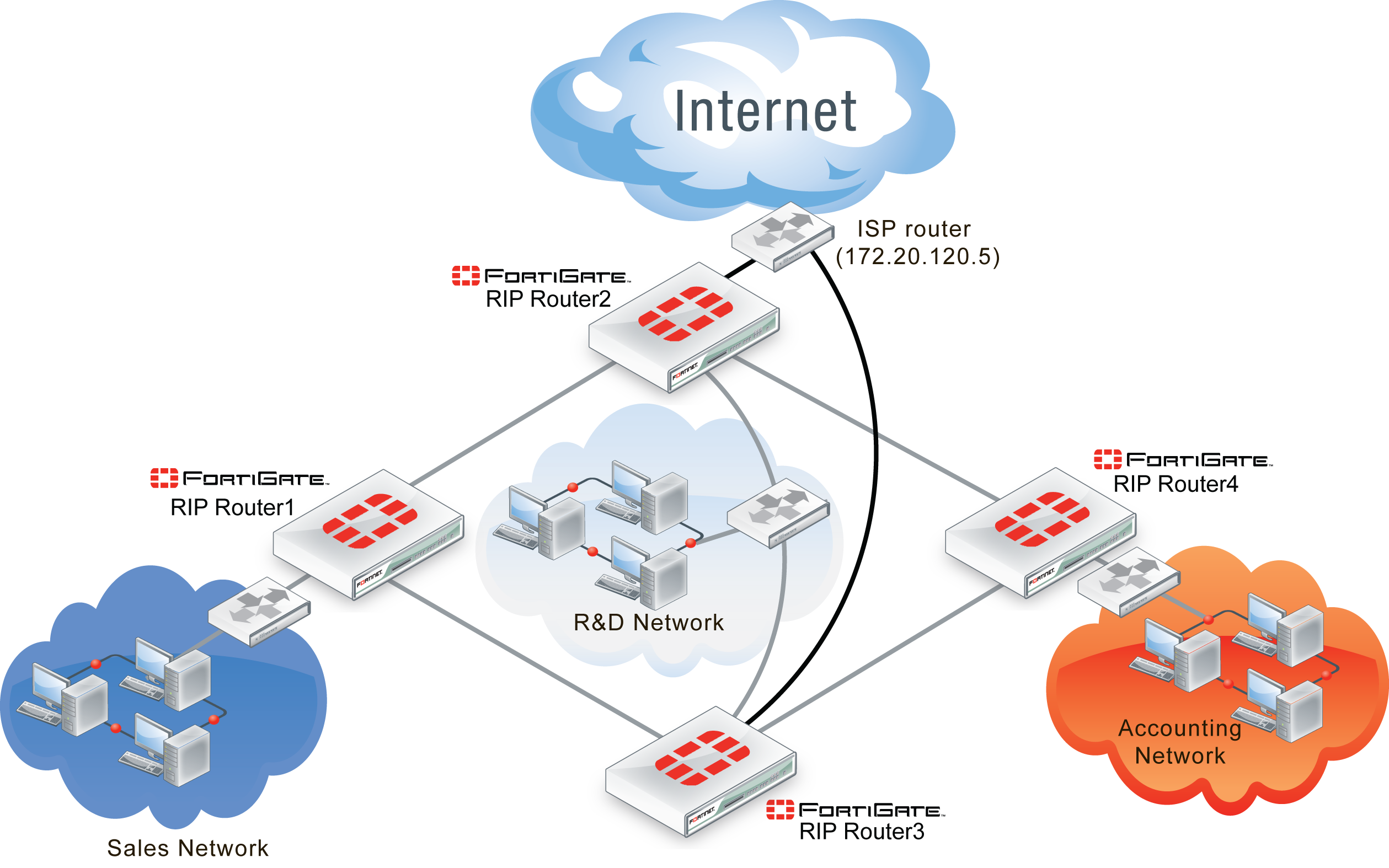
Your company has 3 departments each with their own network — Sales, R&D, and Accounting. Each network has routers that are not running RIP as well as FortiGate units running RIP.
The R&D network has two RIP routers, and each is connected to both other departments as well as being connected to the Internet through the ISP router. The links to the Internet are indicated in black.
The three internal networks do not run RIP. They use static routing because they are small networks. This means the FortiGate units have to redistribute any static routes they learn so that the internal networks can communicate with each other.
Where possible in this example, the default values will be used or the most general settings. This is intended to provide an easier configuration that will require less troubleshooting.
In this example the routers, networks, interfaces used, and IP addresses are as follows. Note that the Interfaces that connect Router2 and Router3 also connect to the R&D network.
RIP example network topology
| Network | Router | Interface & Alias | IP address |
|---|---|---|---|
| Sales | Router1 | port1 (internal) | 10.11.101.101 |
| port2 (router2) | 10.11.201.101 | ||
| port3 (router3) | 10.11.202.101 | ||
| R&D | Router2 | port1 (internal) | 10.12.101.102 |
| port2 (router1) | 10.11.201.102 | ||
| port3 (router4) | 10.14.201.102 | ||
| port4 (ISP) | 172.20.120.102 | ||
| Router3 | port1 (internal) | 10.12.101.103 | |
| port2 (router1) | 10.11.201.103 | ||
| port3 (router4) | 10.14.202.103 | ||
| port4 (ISP) | 172.20.120.103 | ||
| Accounting | Router4 | port1 (internal) | 10.14.101.104 |
| port2 (router2) | 10.14.201.104 | ||
| port3 (router3) | 10.14.202.104 |
Network topology for the simple RIP example
Assumptions
The following assumptions have been made concerning this example.
- All FortiGate units have 5.0 firmware, and are running factory default settings.
- All CLI and web-based manager navigation assumes the unit is running in NAT/Route operating mode, with VDOMs disabled.
- All FortiGate units have interfaces labelled port1 through port4 as required.
- All firewalls have been configured for each FortiGate unit to allow the required traffic to flow across interfaces.
- Only FortiGate units are running RIP on the internal networks.
- Router2 and Router3 are connected through the internal network for R&D.
- Router2 and Router3 each have their own connection to the Internet, indicated in black in the diagram above.
General configuration steps
This example is very straight forward. The only steps involved are:
- Configuring the FortiGate units system information
- Configuring FortiGate unit RIP router information
- Configuring other networking devices
- Testing network configuration
Configuring the FortiGate units system information
Each FortiGate unit needs their hostname, and interfaces configured.
For IP numbering, Router2 and Router3 use the other routers numbering where needed.
Router2 and Router3 have dead gateway detection enabled on the ISP interfaces using Ping. Remember to contact the ISP and confirm their server has ping enabled.
Configure the hostname, interfaces, and default route
To configure Router1 system information - web-based manager
- Go to System > Dashboard > Status > System Information.
- Next to Host Name select Change, and enter “Router1”.
- Go to Router > Static > Static Routes.
- Edit the default route and enter the following information:
| Destination IP/Mask | 0.0.0.0/0.0.0.0 |
| Device | port2 (router2) |
| Gateway | 172.20.120.5/255.255.255.0 |
| Distance | 40 |
- Enter a second default route and enter the following information:
| Destination IP/Mask | 0.0.0.0/0.0.0.0 |
| Device | port3 (router3) |
| Gateway | 172.20.120.5/255.255.255.0 |
| Distance | 40 |
- Go to System > Network > Interfaces.
- Edit port1 (internal) interface.
- Set the following information, and select OK.
| Alias | internal |
| IP/Network Mask | 10.11.101.101/255.255.255.0 |
| Administrative Access | HTTPS SSH PING |
| Description | Internal sales network |
| Administrative Status | Up |
- Edit port2 (router2) interface.
- Set the following information, and select OK.
| Alias | router2 |
| IP/Network Mask | 10.11.201.101/255.255.255.0 |
| Administrative Access | HTTPS SSH PING |
| Description | Link to R&D network & Internet through Router2 |
| Administrative Status | Up |
- Edit port3 (router3) interface.
- Set the following information, and select OK.
| Alias | router3 |
| IP/Network Mask | 10.11.202.101/255.255.255.0 |
| Administrative Access | HTTPS SSH PING |
| Description | Link to R&D network and Internet through Router3 |
| Administrative Status | Up |
To configure Router1 system information - CLI
config system global
set hostname Router1
end
config router static
edit 1
set device "port2"
set distance 45
set gateway 10.11.201.102
next
edit 2
set device “port3”
set distance 45
set gateway 10.11.202.103
end
end
config system interface
edit port1
set alias internal
set ip 10.11.101.101/255.255.255.0
set allowaccess https ssh ping
set description “Internal sales network”
next
edit port2
set alias ISP
set allowaccess https ssh ping
set ip 10.11.201.101/255.255.255.0
set description “Link to R&D network & Internet through Router2”
next
edit port3
set alias router3
set ip 10.11.202.101/255.255.255.0
set allowaccess https ssh ping
set description “Link to R&D network & Internet through Router2”
end
end
To configure Router2 system information - web-based manager
- Go to System > Dashboard > Status > System Information.
- Next to Host Name select Change, and enter “Router2”.
- Go to Router > Static > Static Routes.
- Edit the default route and enter the following information:
| Destination IP/Mask | 0.0.0.0/0.0.0.0 |
| Device | port4 (ISP) |
| Gateway | 172.20.120.5/255.255.255.0 |
| Distance | 5 |
- Go to System > Network > Interfaces.
- Edit port1 (internal) interface.
- Set the following information, and select OK.
| Alias | internal |
| IP/Network Mask | 10.12.101.102/255.255.255.0 |
| Administrative Access | HTTPS SSH PING |
| Description | R&D internal network and Router3 |
| Administrative Status | Up |
- Edit port2 (router1) interface.
- Set the following information, and select OK.
| Alias | router1 |
| IP/Network Mask | 10.12.201.102/255.255.255.0 |
| Administrative Access | HTTPS SSH PING |
| Description | Link to Router1 and the Sales network |
| Administrative Status | Up |
- Edit port3 (router4) interface.
- Set the following information, and select OK.
| Alias | router4 |
| IP/Network Mask | 10.12.301.102/255.255.255.0 |
| Administrative Access | HTTPS SSH PING |
| Description | Link to Router4 and the accounting network |
| Administrative Status | Up |
- Edit port4 (ISP) interface.
- Set the following information, and select OK.
| Alias | ISP |
| IP/Network Mask | 172.20.120.102/255.255.255.0 |
| Administrative Access | HTTPS SSH PING |
| Detect and Identify Devices | enable |
| Description | Internet through ISP |
| Administrative Status | Up |
To configure Router2 system information - CLI
config system global
set hostname Router2
end
config router static
edit 1
set device "port4"
set distance 5
set gateway 172.20.130.5
end
end
config system interface
edit port1
set alias internal
set ip 10.11.101.102/255.255.255.0
set allowaccess https ssh ping
set description “Internal RnD network and Router3”
next
edit port2
set alias router1
set allowaccess https ssh ping
set ip 10.11.201.102/255.255.255.0
set description “Link to Router1”
next
edit port3
set alias router3
set ip 10.14.202.102/255.255.255.0
set allowaccess https ssh ping
set description “Link to Router4”
next
edit port4
set alias ISP
set ip 172.20.120.102/255.255.255.0
set allowaccess https ssh ping
set description “ISP and Internet”
end
end
To configure Router3 system information - web-based manager
- Go to System > Dashboard > Status > System Information.
- Next to Host Name select Change, and enter “Router3”.
- Go to Router > Static > Static Routes.
- Edit the default route and enter the following information:
| Destination IP/Mask | 0.0.0.0/0.0.0.0 |
| Device | port4 (ISP) |
| Gateway | 172.20.120.5/255.255.255.0 |
| Distance | 5 |
- Go to System > Network > Interfaces.
- Edit port1 (internal) interface.
- Set the following information, and select OK.
| Alias | internal |
| IP/Network Mask | 10.12.101.103/255.255.255.0 |
| Administrative Access | HTTPS SSH PING |
| Description | R&D internal network and Router2 |
| Administrative Status | Up |
- Edit port2 (router1) interface.
- Set the following information, and select OK.
| Alias | router1 |
| IP/Network Mask | 10.13.201.103/255.255.255.0 |
| Administrative Access | HTTPS SSH PING |
| Description | Link to Router1 and Sales network |
| Administrative Status | Up |
- Edit port3 (router4) interface.
- Set the following information, and select OK.
| Alias | router4 |
| IP/Network Mask | 10.13.301.103/255.255.255.0 |
| Administrative Access | HTTPS SSH PING |
| Description | Link to Router4 and accounting network |
| Administrative Status | Up |
- Edit port4 (ISP) interface.
- Set the following information, and select OK.
| Alias | ISP |
| IP/Network Mask | 172.20.120.103/255.255.255.0 |
| Administrative Access | HTTPS SSH PING |
| Detect and Identify Devices | enable |
| Description | Internet and ISP |
| Administrative Status | Up |
To configure Router3 system information - CLI
config system global
set hostname Router3
end
config router static
edit 1
set device "port4"
set distance 5
set gateway 172.20.130.5
end
end
config system interface
edit port1
set alias internal
set ip 10.12.101.103/255.255.255.0
set allowaccess https ssh ping
set description “Internal RnD network and Router2”
next
edit port2
set alias ISP
set allowaccess https ssh ping
set ip 10.11.201.103/255.255.255.0
set description “Link to Router1”
next
edit port3
set alias router3
set ip 10.14.202.103/255.255.255.0
set allowaccess https ssh ping
set description “Link to Router4”
next
edit port4
set alias ISP
set ip 172.20.120.103/255.255.255.0
set allowaccess https ssh ping
set description “ISP and Internet”
end
end
To configure Router4 system information - web-based manager
- Go to System > Dashboard > Status > System Information.
- Next to Host Name select Change, and enter “Router4”.
- Go to Router > Static > Static Routes.
- Edit the default route and enter the following information:
| Destination IP/Mask | 0.0.0.0/0.0.0.0 |
| Device | port2 (router2) |
| Gateway | 172.20.120.5/255.255.255.0 |
| Distance | 40 |
- Enter a second default route and enter the following information:
| Destination IP/Mask | 0.0.0.0/0.0.0.0 |
| Device | port3 (router3) |
| Gateway | 172.20.120.5/255.255.255.0 |
| Distance | 40 |
- Go to System > Network > Interfaces.
- Edit port 1 (internal) interface.
- Set the following information, and select OK.
| Alias | internal |
| IP/Network Mask | 10.14.101.104/255.255.255.0 |
| Administrative Access | HTTPS SSH PING |
| Description | Internal accounting network |
| Administrative Status | Up |
- Edit port 2 (router2) interface.
- Set the following information, and select OK.
| Alias | router2 |
| IP/Network Mask | 10.14.201.104/255.255.255.0 |
| Administrative Access | HTTPS SSH PING |
| Description | Link to R&D network & Internet through Router2 |
| Administrative Status | Up |
- Edit port 3 (router3) interface.
- Set the following information, and select OK.
| Alias | router3 |
| IP/Network Mask | 10.14.301.104/255.255.255.0 |
| Administrative Access | HTTPS SSH PING |
| Description | Link to R&D network and Internet through Router3 |
| Administrative Status | Up |
To configure Router4 system information - CLI
config system global
set hostname Router4
end
config router static
edit 1
set device "port2"
set distance 45
set gateway 10.14.201.102
next
edit 2
set device “port3”
set distance 45
set gateway 10.14.202.103
end
end
config system interface
edit port1
set alias internal
set ip 10.14.101.104/255.255.255.0
set allowaccess https ssh ping
set description “Internal sales network”
next
edit port2
set alias router2
set allowaccess https ssh ping
set ip 10.14.201.104/255.255.255.0
set description “Link to R&D network & Internet through Router2”
next
edit port3
set alias router3
set ip 10.14.202.104/255.255.255.0
set allowaccess https ssh ping
set description “Link to R&D network & Internet through Router2”
end
end
Configuring FortiGate unit RIP router information
With the interfaces configured, RIP can now be configured on the FortiGate units.
For each FortiGate unit the following steps will be taken:
- Configure RIP version used
- Redistribute static networks
- Add networks serviced by RIP
- Add interfaces that support RIP on the FortiGate unit
Router1 and Router4 are configured the same. Router2 and Router3 are configured the same. These routers will be grouped accordingly for the following procedures — repeat the procedures once for each FortiGate unit.
Configure RIP settings on Router1 and Router4 - web-based manager
- Go to Router > Dynamic > RIP.
- Select 2 for RIP Version.
- In Advanced Options, under Redistribute enable Static.
- Leave the other Advanced Options at default values.
- Enter the following networks, and select Add after each:
- 10.11.0.0/255.255.0.0
- 10.12.0.0/255.255.0.0
- 10.14.0.0/255.255.0.0
- 172.20.120.0/255.255.255.0
- For interface, select Create and set the following information.
| Interface | port1 (internal) |
| Send Version | Both |
| Receive Version | Both |
| Authentication | None |
| Passive Interface | disabled |
- For interface, select Create and set the following information.
| Interface | port2 (router2) |
| Send Version | Both |
| Receive Version | Both |
| Authentication | None |
| Passive Interface | disabled |
- For interface, select Create and set the following information.
| Interface | port3 (router3) |
| Send Version | Both |
| Receive Version | Both |
| Authentication | None |
| Passive Interface | disabled |
Configure RIP settings on Router1 and Router4 - CLI
config router rip
set version 2
config interface
edit "port1"
set receive-version 1 2
set send-version 1 2
next
edit "port2"
set receive-version 1 2
set send-version 1 2
next
edit "port3"
set receive-version 1 2
set send-version 1 2
end
config network
edit 1
set prefix 10.11.0.0 255.255.0.0
next
edit 2
set prefix 10.12.0.0 255.255.0.0
next
edit 3
set prefix 10.14.0.0 255.255.0.0
next
edit 4
set prefix 172.20.120.0 255.255.255.0
end
config redistribute "static"
set status enable
end
end
Configure RIP settings on Router2 and Router3- web-based manager
- Go to Router > Dynamic > RIP.
- Select 2 for RIP Version.
- In Advanced Options, under Redistribute enable Static.
- Leave the other Advanced Options at default values.
- Enter the following networks, and select Add after each:
- 10.11.0.0/255.255.0.0
- 10.12.0.0/255.255.0.0
- 10.14.0.0/255.255.0.0
- 172.20.120.0/255.255.255.0
- For interface, select Create and set the following information.
| Interface | port1 (internal) |
| Send Version | Both |
| Receive Version | Both |
| Authentication | None |
| Passive Interface | disabled |
- For interface, select Create and set the following information.
| Interface | port2 (router1) |
| Send Version | Both |
| Receive Version | Both |
| Authentication | None |
| Passive Interface | disabled |
- For interface, select Create and set the following information.
| Interface | port3 (router4) |
| Send Version | Both |
| Receive Version | Both |
| Authentication | None |
| Passive Interface | disabled |
- For interface, select Create and set the following information.
| Interface | port4 (ISP) |
| Send Version | Both |
| Receive Version | Both |
| Authentication | None |
| Passive Interface | disabled |
Configure RIP settings on Router2 and Router3- web-based manager
config router rip
set version 2
config interface
edit "port1"
set receive-version 1 2
set send-version 1 2
next
edit "port2"
set receive-version 1 2
set send-version 1 2
next
edit "port3"
set receive-version 1 2
set send-version 1 2
end
edit "port4"
set receive-version 1 2
set send-version 1 2
end
config network
edit 1
set prefix 10.11.0.0 255.255.0.0
next
edit 2
set prefix 10.12.0.0 255.255.0.0
next
edit 3
set prefix 10.14.0.0 255.255.0.0
next
edit 4
set prefix 172.20.120.0 255.255.255.0
end
config redistribute "static"
set status enable
end
end
Configuring other networking devices
In this example there are two groups of other devices on the the network — internal devices, and the ISP.
The first is the internal network devices on the Sales, R&D, and Accounting networks. This includes simple static routers, computers, printers and other network devices. Once the FortiGate units are configured, the internal static routers need to be configured using the internal network IP addresses. Otherwise there should be no configuration required.
The second group of devices is the ISP. This consists of the RIP router the FortiGate routers 2 and 3 connect to. You need to contact your ISP and ensure they have your information for your network such as the IP addresses of the connecting RIP routers, what version of RIP your network supports, and what authentication (if any) is used.
Testing network configuration
Once the network has been configured, you need to test that it works as expected.
The two series of tests you need to run are to test the internal networks can communicate with each other, and that the internal networks can reach the Internet.
Use ping, traceroute, and other networking tools to run these tests.
If you encounter problems, for troubleshooting help consult Simple RIP example.
Copyright © 2018 Fortinet, Inc. All Rights Reserved. | Terms of Service | Privacy Policy
