
Full mesh HA
This chapter provides an introduction to full mesh HA and also contains general procedures and configuration examples that describe how to configure FortiGate full mesh HA.
The examples in this chapter include example values only. In most cases you will substitute your own values. The examples in this chapter also do not contain detailed descriptions of configuration parameters.
Full mesh HA overview
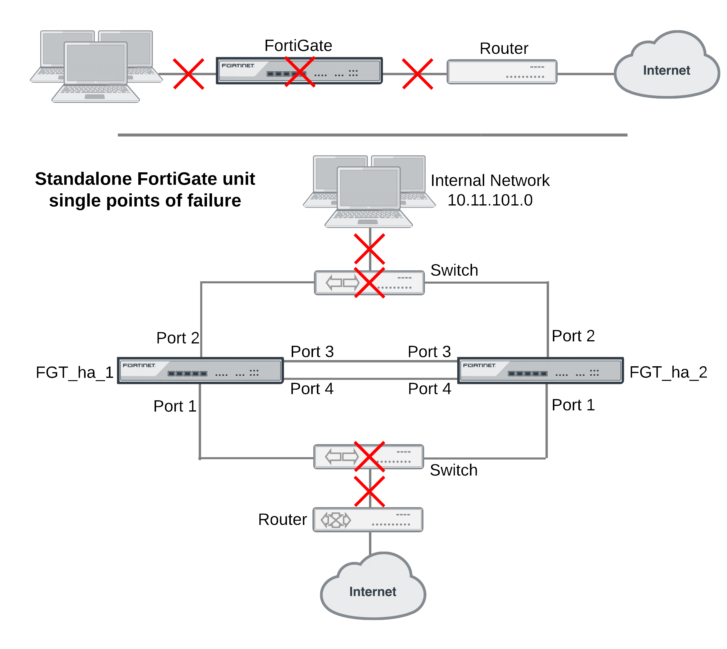
When two or more FortiGate units are connected to a network in an HA cluster the reliability of the network is improved because the HA cluster replaces a single FortiGate unit as a single point of failure. With a cluster, a single FortiGate unit is replaced by a cluster of two or more FortiGate units.
However, even with a cluster, potential single points of failure remain. The interfaces of each cluster unit connect to a single switch and that switch provides a single connection to the network. If the switch fails or if the connection between the switch and the network fails service is interrupted to that network.
The HA cluster does improve the reliability of the network because switches are not as complex components as FortiGate units, so are less likely to fail. However, for even greater reliability, a configuration is required that includes redundant connections between the cluster the networks that it is connected to.
FortiGate models that support 802.3ad Aggregate or Redundant interfaces can be used to create a cluster configuration called full mesh HA. Full mesh HA is a method of reducing the number of single points of failure on a network that includes an HA cluster.
This redundant configuration can be achieved using FortiGate 802.3ad Aggregate or Redundant interfaces and a full mesh HA configuration. In a full mesh HA configuration, you connect an HA cluster consisting of two or more FortiGate units to the network using 802.3ad Aggregate or Redundant interfaces and redundant switches. Each 802.3ad Aggregate or Redundant interface is connected to two switches and both of these switches are connected to the network. In addition you must set up an IEEE 802.1Q (also called Dot1Q) or ISL link between the redundant switches connected to the Aggregate or Redundant interfaces.
The resulting full mesh configuration, an example is shown below, includes redundant connections between all network components. If any single component or any single connection fails, traffic automatically switches to the redundant component and connection and traffic flow resumes.
Single points of failure in a standalone and HA network configuration
Full mesh HA and redundant heartbeat interfaces
A full mesh HA configuration also includes redundant HA heartbeat interfaces. At least two heartbeat interfaces should be selected in the HA configuration and both sets of HA heartbeat interfaces should be connected. The HA heartbeat interfaces do not have to be configured as redundant interfaces because the FGCP handles failover between heartbeat interfaces.
Full mesh HA, redundant interfaces and 802.3ad aggregate interfaces
Full mesh HA is supported for both redundant interfaces and 802.3ad aggregate interfaces. In most cases you would simply use redundant interfaces. However, if your switches support 802.3ad aggregate interfaces and split multi-trunking you can use aggregate interfaces in place of redundant interfaces for full mesh HA. One advantage of using aggregate interfaces is that all of the physical interfaces in the aggregate interface can send and receive packets. As a result, using aggregate interfaces may increase the bandwidth capacity of the cluster.
Usually redundant and aggregate interfaces consist of two physical interfaces. However, you can add more than two physical interfaces to a redundant or aggregate interface. Adding more interfaces can increase redundancy protection. Adding more interfaces can also increase bandwidth capacity if you are using 802.3ad aggregate interfaces.
Example full mesh HA configuration
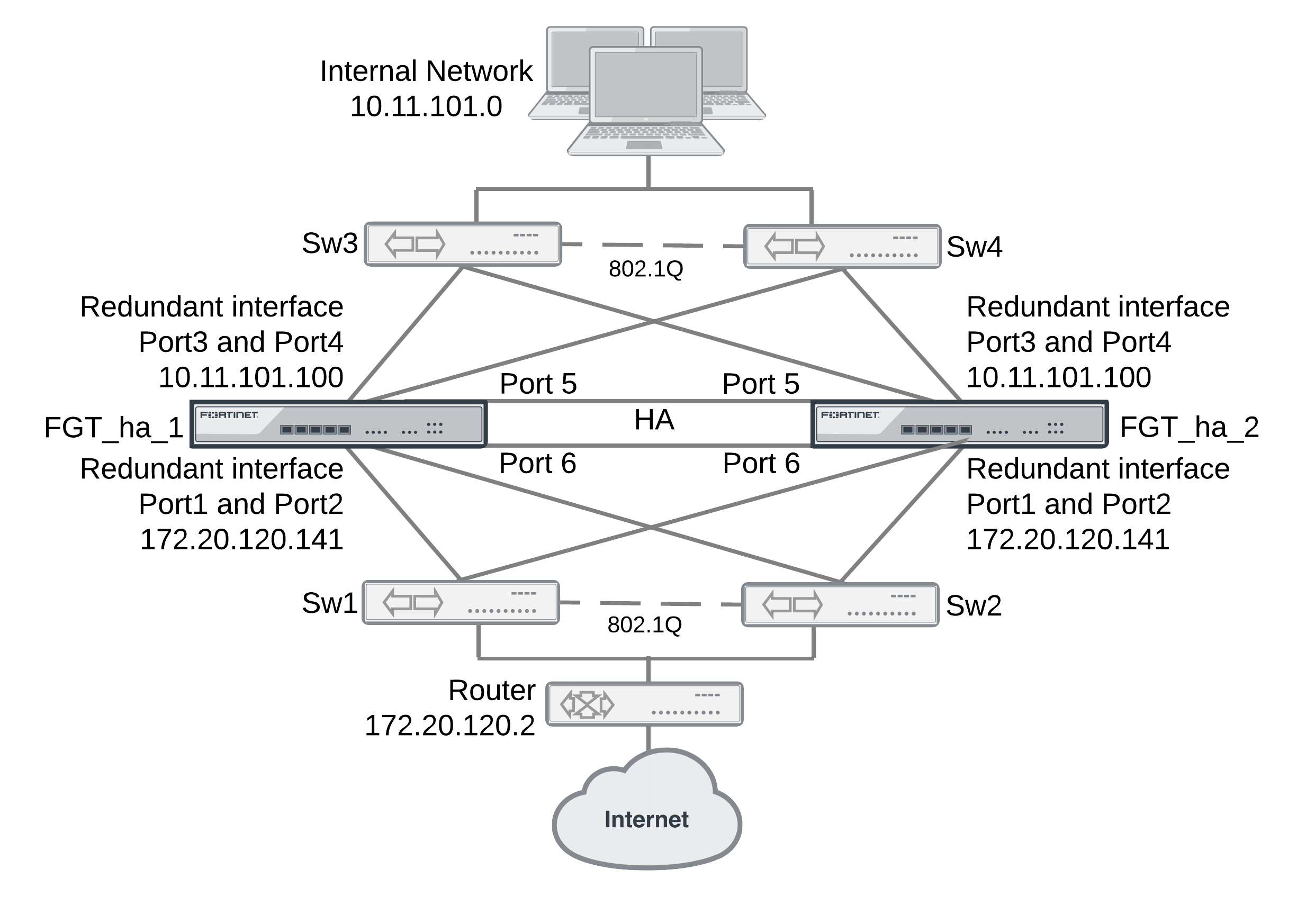
The following figure shows a full mesh HA configuration with a cluster of two FortiGate units. This section describes the FortiGate configuration settings and network components required for a full mesh HA configuration. This section also contains example steps for setting up this full mesh HA configuration. The procedures in this section describe one of many possible sequences of steps for configuring full mesh HA. As you become more experienced with FortiOS, HA, and full mesh HA you may choose to use a different sequence of configuration steps.
Full Mesh HA configuration
For simplicity these procedures assume that you are starting with two new FortiGate units set to the factory default configuration. However, starting from the default configuration is not a requirement for a successful HA deployment. FortiGate HA is flexible enough to support a successful configuration from many different starting points.
These procedures describe how to configure a cluster operating in NAT/Route mode because NAT/Route is the default FortiGate operating mode. However, the steps are the same if the cluster operates in Transparent mode. You can either switch the cluster units to operate in Transparent mode before beginning these procedures, or you can switch the cluster to operate in Transparent mode after HA is configured and the cluster is connected and operating.
Full mesh HA configuration
The two FortiGate units (FGT_ha_1 and FGT_ha_2) can be operating in NAT/Route or Transparent mode. Aside from the standard HA settings, the FortiGate configuration includes the following:
- The port5 and port6 interfaces configured as heartbeat interfaces. A full mesh HA configuration also includes redundant HA heartbeat interfaces.
- The port1 and port2 interfaces added to a redundant interface. Port1 is the active physical interface in this redundant interface. To make the port1 interface the active physical interface it should appear above the port2 interface in the redundant interface configuration.
- The port3 and port4 interfaces added to a redundant interface. Port3 is the active physical interface in this redundant interface. To make the port3 interface the active physical interface it should appear above the port4 interface in the redundant interface configuration.
Full mesh switch configuration
The following redundant switch configuration is required:
- Two redundant switches (Sw3 and Sw4) connected to the internal network. Establish an 802.1Q (Dot1Q) or interswitch-link (ISL) connection between them.
- Two redundant switches (Sw1 and Sw2) connected to the Internet. Establish an 802.1Q (Dot1Q) or interswitch-link (ISL) connection between them.
Full mesh network connections
Make the following physical network connections for FGT_ha_1:
- Port1 to Sw1 (active)
- Port2 to Sw2 (inactive)
- Port3 to Sw3 (active)
- Port4 to Sw4 (inactive)
Make the following physical network connections for FGT_ha_2:
- Port1 to Sw2 (active)
- Port2 to Sw1 (inactive)
- Port3 to Sw4 (active)
- Port4 to Sw3 (inactive)
How packets travel from the internal network through the full mesh cluster and to the Internet
If the cluster is operating in active-passive mode and FGT_ha_2 is the primary unit, all packets take the following path from the internal network to the internet:
- From the internal network to Sw4. Sw4 is the active connection to FGT_ha_2; which is the primary unit. The primary unit receives all packets.
- From Sw4 to the FGT_ha_2 port3 interface. Active connection between Sw4 and FGT_ha_2. Port3 is the active member of the redundant interface.
- From FGT_ha_2 port3 to FGT_ha_2 port1. Active connection between FGT_ha_2 and Sw2. Port1 is the active member of the redundant interface.
- From Sw2 to the external router and the Internet.
Configuring full-mesh HA - web-based manager
Each cluster unit must have the same HA configuration.
To configure the FortiGate units for HA operation
- Register and apply licenses to the FortiGate unit. This includes FortiCloud activation, and FortiClient licensing licensing, and entering a license key if you purchased more than 10 Virtual Domains (VDOMS).

- You can also install any third-party certificates on the primary FortiGate before forming the cluster. Once the cluster is formed third-party certificates are synchronized to the backup FortiGate.
FortiToken licenses can be added at any time because they are synchronized to all cluster members. - On the System Information dashboard widget, beside Host Name select Change.
- Enter a new Host Name for this FortiGate unit.
| New Name | FGT_ha_1 |
- Go to System > Config > HA and change the following settings.
| Mode | Active-Active | |
| Group Name | Rexample1.com | |
| Password | RHA_pass_1 | |
| Heartbeat Interface | ||
| Enable | Priority | |
| port5 | Select | 50 |
| port6 | Select | 50 |
- Select OK.
The FortiGate unit negotiates to establish an HA cluster. When you select OK you may temporarily lose connectivity with the FortiGate unit as the HA cluster negotiates and the FGCP changes the MAC address of the FortiGate unit interfaces. The MAC addresses of the FortiGate interfaces change to the following virtual MAC addresses:
- port1 interface virtual MAC:
00-09-0f-09-00-00 - port10 interface virtual MAC:
00-09-0f-09-00-01 - port11 interface virtual MAC:
00-09-0f-09-00-02 - port12 interface virtual MAC:
00-09-0f-09-00-03 - port13 interface virtual MAC:
00-09-0f-09-00-04 - port14 interface virtual MAC:
00-09-0f-09-00-05 - port15 interface virtual MAC:
00-09-0f-09-00-06 - port16 interface virtual MAC:
00-09-0f-09-00-07 - port17 interface virtual MAC:
00-09-0f-09-00-08 - port18 interface virtual MAC:
00-09-0f-09-00-09 - port19 interface virtual MAC:
00-09-0f-09-00-0a - port2 interface virtual MAC:
00-09-0f-09-00-0b - port20 interface virtual MAC:
00-09-0f-09-00-0c - port3 interface virtual MAC:
00-09-0f-09-00-0d - port4 interface virtual MAC:
00-09-0f-09-00-0e - port5 interface virtual MAC:
00-09-0f-09-00-0f - port6 interface virtual MAC:
00-09-0f-09-00-10 - port7 interface virtual MAC:
00-09-0f-09-00-11 - port8 interface virtual MAC:
00-09-0f-09-00-12 - port9 interface virtual MAC:
00-09-0f-09-00-13
To be able to reconnect sooner, you can update the ARP table of your management PC by deleting the ARP table entry for the FortiGate unit (or just deleting all arp table entries). You may be able to delete the arp table of your management PC from a command prompt using a command similar to
arp -d.
You can use the
get hardware nic(ordiagnose hardware deviceinfo nic) CLI command to view the virtual MAC address of any FortiGate unit interface. For example, use the following command to view the port1 interface virtual MAC address (Current_HWaddr) and the port1 permanent MAC address (Permanent_HWaddr):
get hardware nic port1
.
.
.
MAC: 00:09:0f:09:00:00
Permanent_HWaddr: 02:09:0f:78:18:c9
.
.
.
- Power off the first FortiGate unit.
- Repeat these steps for the second FortiGate unit.
Set the second FortiGate unit host name to:
| New Name | FGT_ha_2 |
To connect the cluster to your network
- Make the following physical network connections for FGT_ha_1:
- Port1 to Sw1 (active)
- Port2 to Sw2 (inactive)
- Port3 to Sw3 (active)
- Port4 to Sw4 (inactive)
- Make the following physical network connections for FGT_ha_2:
- Port1 to Sw2 (active)
- Port2 to Sw1 (inactive)
- Port3 to Sw4 (active)
- Port4 to Sw3 (inactive)
- Connect Sw3 and Sw4 to the internal network.
- Connect Sw1 and Sw2 to the external router.
- Enable 802.1Q (Dot1Q) or ISL communication between Sw1 and Sw2 and between Sw3 and Sw4.
- Power on the cluster units.
The units start and negotiate to choose the primary unit and the subordinate unit. This negotiation occurs with no user intervention.
When negotiation is complete the cluster is ready to be configured for your network.
To view cluster status
Use the following steps to view the cluster dashboard and cluster members list to confirm that the cluster units are operating as a cluster.
- View the system dashboard.
The System Information dashboard widget shows the Cluster Name (Rexample1.com) and the host names and serial numbers of the Cluster Members. The Unit Operation widget shows multiple cluster units.
- Go to System > Config > HA to view the cluster members list.
The list shows two cluster units, their host names, their roles in the cluster, and their priorities. You can use this list to confirm that the cluster is operating normally.
To troubleshoot the cluster configuration
If the cluster members list and the dashboard does not display information for both cluster units the FortiGate units are not functioning as a cluster. See Troubleshooting full mesh HA to troubleshoot the cluster.
To add basic configuration settings and the redundant interfaces
Use the following steps to add a few basic configuration settings.
- Log into the cluster web-based manager.
- Go to System > Admin > Administrators.
- Edit admin and select Change Password.
- Enter and confirm a new password.
- Select OK.
- Go to Router > Static > Static Routes and temporarily delete the default route.
You cannot add an interface to a redundant interface if any settings (such as the default route) are configured for it.
- Go to System > Network > Interfaces and select Create New and configure the redundant interface to connect to the Internet.
| Name | Port1_Port2 |
| Type | Redundant |
| Physical Interface Members | |
| Selected Interfaces | port1, port2 |
| IP/Netmask | 172.20.120.141/24 |
- Select OK.
- Select Create New and configure the redundant interface to connect to the internal network.
| Name | Port3_Port4 |
| Type | Redundant |
| Physical Interface Members | |
| Selected Interfaces | port3, port4 |
| IP/Netmask | 10.11.101.100/24 |
| Administrative Access | HTTPS, PING, SSH |
- Select OK.
The virtual MAC addresses of the FortiGate interfaces change to the following. Notice that port1 and port2 both have the port1 virtual MAC address and port3 and port4 both have the port3 virtual MAC address:
- port1 interface virtual MAC:
00-09-0f-09-00-00 - port10 interface virtual MAC:
00-09-0f-09-00-01 - port11 interface virtual MAC:
00-09-0f-09-00-02 - port12 interface virtual MAC:
00-09-0f-09-00-03 - port13 interface virtual MAC:
00-09-0f-09-00-04 - port14 interface virtual MAC:
00-09-0f-09-00-05 - port15 interface virtual MAC:
00-09-0f-09-00-06 - port16 interface virtual MAC:
00-09-0f-09-00-07 - port17 interface virtual MAC:
00-09-0f-09-00-08 - port18 interface virtual MAC:
00-09-0f-09-00-09 - port19 interface virtual MAC:
00-09-0f-09-00-0a - port2 interface virtual MAC:
00-09-0f-09-00-00(same as port1) - port20 interface virtual MAC:
00-09-0f-09-00-0c - port3 interface virtual MAC:
00-09-0f-09-00-0d - port4 interface virtual MAC:
00-09-0f-09-00-0d(same as port3) - port5 interface virtual MAC:
00-09-0f-09-00-0f - port6 interface virtual MAC:
00-09-0f-09-00-10 - port7 interface virtual MAC:
00-09-0f-09-00-11 - port8 interface virtual MAC:
00-09-0f-09-00-12 - port9 interface virtual MAC:
00-09-0f-09-00-13
- Go to Router > Static > Static Routes.
- Add the default route.
| Destination IP/Mask | 0.0.0.0/0.0.0.0 |
| Gateway | 172.20.120.2 |
| Device | Port1_Port2 |
| Distance | 10 |
- Select OK.
To configure HA port monitoring for the redundant interfaces
- Go to System > Config > HA.
- In the cluster members list, edit the primary unit.
- Configure the following port monitoring for the redundant interfaces:
| Port Monitor | |
| Port1_Port2 | Select |
| Port3_Port4 | Select |
- Select OK.
Configuring Full Mesh HA - CLI
Each cluster must have the same HA configuration. Use the following procedure to configure the FortiGate units for HA operation.
To configure the FortiGate units for HA operation
- Register and apply licenses to the FortiGate unit. This includes FortiCloud activation, and FortiClient licensing, and entering a license key if you purchased more than 10 Virtual Domains (VDOMS).
- You can also install any third-party certificates on the primary FortiGate before forming the cluster. Once the cluster is formed third-party certificates are synchronized to the backup FortiGate.
FortiToken licenses can be added at any time because they are synchronized to all cluster members. - Enter a new Host Name for this FortiGate unit.
config system global
set hostname FGT_ha_1
end
- Configure HA settings.
config system ha
set mode a-a
set group-name Rexample1.com
set password RHA_pass_1
set hbdev port5 50 port6 50
end
The FortiGate unit negotiates to establish an HA cluster. When you select OK you may temporarily lose connectivity with the FortiGate unit as the HA cluster negotiates and the FGCP changes the MAC address of the FortiGate unit interfaces. The MAC addresses of the FortiGate interfaces change to the following virtual MAC addresses:
- port1 interface virtual MAC:
00-09-0f-09-00-00 - port10 interface virtual MAC:
00-09-0f-09-00-01 - port11 interface virtual MAC:
00-09-0f-09-00-02 - port12 interface virtual MAC:
00-09-0f-09-00-03 - port13 interface virtual MAC:
00-09-0f-09-00-04 - port14 interface virtual MAC:
00-09-0f-09-00-05 - port15 interface virtual MAC:
00-09-0f-09-00-06 - port16 interface virtual MAC:
00-09-0f-09-00-07 - port17 interface virtual MAC:
00-09-0f-09-00-08 - port18 interface virtual MAC:
00-09-0f-09-00-09 - port19 interface virtual MAC:
00-09-0f-09-00-0a - port2 interface virtual MAC:
00-09-0f-09-00-0b - port20 interface virtual MAC:
00-09-0f-09-00-0c - port3 interface virtual MAC:
00-09-0f-09-00-0d - port4 interface virtual MAC:
00-09-0f-09-00-0e - port5 interface virtual MAC:
00-09-0f-09-00-0f - port6 interface virtual MAC:
00-09-0f-09-00-10 - port7 interface virtual MAC:
00-09-0f-09-00-11 - port8 interface virtual MAC:
00-09-0f-09-00-12 - port9 interface virtual MAC:
00-09-0f-09-00-13
To be able to reconnect sooner, you can update the ARP table of your management PC by deleting the ARP table entry for the FortiGate unit (or just deleting all arp table entries). You may be able to delete the arp table of your management PC from a command prompt using a command similar to
arp -d.You can use the
get hardware nic(ordiagnose hardware deviceinfo nic) CLI command to view the virtual MAC address of any FortiGate unit interface. For example, use the following command to view the port1 interface virtual MAC address (Current_HWaddr) and the port1 permanent MAC address (Permanent_HWaddr):
get hardware nic port1
.
.
.
MAC: 00:09:0f:09:00:00
Permanent_HWaddr: 02:09:0f:78:18:c9
.
.
.
- Power off the first FortiGate unit.
- Repeat these steps for the second FortiGate unit.
Set the other FortiGate unit host name to:
config system global
set hostname FGT_ha_2
end
To connect the cluster to your network
- Make the following physical network connections for FGT_ha_1:
- Port1 to Sw1 (active)
- Port2 to Sw2 (inactive)
- Port3 to Sw3 (active)
- Port4 to Sw4 (inactive)
- Make the following physical network connections for FGT_ha_2:
- Port1 to Sw2 (active)
- Port2 to Sw1 (inactive)
- Port3 to Sw4 (active)
- Port4 to Sw3 (inactive)
- Connect Sw3 and Sw4 to the internal network.
- Connect Sw1 and Sw2 to the external router.
- Enable 802.1Q (Dot1Q) or ISL communication between Sw1 and Sw2 and between Sw3 and Sw4.
- Power on the cluster units.
The units start and negotiate to choose the primary unit and the subordinate unit. This negotiation occurs with no user intervention.
When negotiation is complete the cluster is ready to be configured for your network.
To view cluster status
Use the following steps to view cluster status from the CLI.
- Log into the CLI.
- Enter
get system statusto verify the HA status of the cluster unit that you logged into.
If the command output includes
Current HA mode: a-a, master, the cluster units are operating as a cluster and you have connected to the primary unit.If the command output includes
Current HA mode: a-a, backup, you have connected to a subordinate unit.If the command output includes
Current HA mode: standalonethe cluster unit is not operating in HA mode.
- Enter the following command to confirm the HA configuration of the cluster:
get system ha status
Model: XXXX
Mode: a-a
Group: 0
Debug: 0
ses_pickup: disable
Master:128 FGT_ha_2 FG600B3908600825 0
Slave :128 FGT_ha_1 FG600B3908600705 1
number of vcluster: 1
vcluster 1: work 169.254.0.1
Master:0 FG600B3908600825
Slave :1 FG600B3908600705
The command output shows both cluster units, their host names, their roles in the cluster, and their priorities. You can use this command to confirm that the cluster is operating normally. For example, if the command shows only one cluster unit then the other unit has left the cluster for some reason.
- Use the
execute ha managecommand to connect to the other cluster unit’s CLI and use these commands to verify cluster status.
To troubleshoot the cluster configuration
If the cluster members list and the dashboard does not display information for both cluster units the FortiGate units are not functioning as a cluster. See Troubleshooting full mesh HA to troubleshoot the cluster.
To add basic configuration settings and the redundant interfaces
Use the following steps to add a few basic configuration settings. Some steps use the CLI and some the web-based manager.
- Log into the cluster CLI.
- Add a password for the admin administrative account.
config system admin
edit admin
set password <password_str>
end
- Temporarily delete the default route.
You cannot add an interface to a redundant interface if any settings (such as the default route) are configured for it.
config router static
delete 1
end
- Go to System > Network > Interface and select Create New to add the redundant interface to connect to the Internet.
- Add the redundant interface to connect to the Internet.
config system interface
edit Port1_Port2
set type redundant
set member port1 port2
end
- Add the redundant interface to connect to the internal network.
config system interface
edit Port3_Port4
set type redundant
set member port3 port4
end
The virtual MAC addresses of the FortiGate interfaces change to the following. Note that port1 and port2 both have the port1 virtual MAC address and port3 and port4 both have the port3 virtual MAC address:
- port1 interface virtual MAC:
00-09-0f-09-00-00 - port10 interface virtual MAC:
00-09-0f-09-00-01 - port11 interface virtual MAC:
00-09-0f-09-00-02 - port12 interface virtual MAC:
00-09-0f-09-00-03 - port13 interface virtual MAC:
00-09-0f-09-00-04 - port14 interface virtual MAC:
00-09-0f-09-00-05 - port15 interface virtual MAC:
00-09-0f-09-00-06 - port16 interface virtual MAC:
00-09-0f-09-00-07 - port17 interface virtual MAC:
00-09-0f-09-00-08 - port18 interface virtual MAC:
00-09-0f-09-00-09 - port19 interface virtual MAC:
00-09-0f-09-00-0a - port2 interface virtual MAC:
00-09-0f-09-00-00(same as port1) - port20 interface virtual MAC:
00-09-0f-09-00-0c - port3 interface virtual MAC:
00-09-0f-09-00-0d - port4 interface virtual MAC:
00-09-0f-09-00-0d(same as port3) - port5 interface virtual MAC:
00-09-0f-09-00-0f - port6 interface virtual MAC:
00-09-0f-09-00-10 - port7 interface virtual MAC:
00-09-0f-09-00-11 - port8 interface virtual MAC:
00-09-0f-09-00-12 - port9 interface virtual MAC:
00-09-0f-09-00-13
- Go to Router > Static > Static Routes.
- Add the default route.
config router static
edit 1
set dst 0.0.0.0 0.0.0.0
set gateway 172.20.120.2
set device Port1_Port2
end
To configure HA port monitoring for the redundant interfaces
- Enter the following command to configure port monitoring for the redundant interfaces:
config system ha
set monitor Port1_Port2 Port3_Port4
end
Troubleshooting full mesh HA
Troubleshooting full mesh HA clusters is similar to troubleshooting any cluster (see FGCP configuration examples and troubleshooting or Troubleshooting virtual clustering). The configuration and operation of a full mesh HA cluster is very similar to the configuration and operation of a standard cluster. The only differences relate to the configuration, connection, and operation of the redundant interfaces and redundant switches.
- Make sure the redundant interfaces and switches are connected correctly. With so many connections it is possible to make mistakes or for cables to become disconnected.
- Confirm that the configuration of the cluster unit 802.3ad Aggregate or Redundant interfaces is correct according to the configuration procedures in this chapter.
- In some configurations with some switch hardware, MAC-learning delays on the inter-switch links on the surrounding topologies may occur. The delays occur if the gratuitous ARP packets sent by the cluster after a failover are delayed by the switches before being sent across the inter-switch link. If this happens the surrounding topologies may be delayed in recognizing the failover and will keep sending packets to the MAC address of the failed primary unit resulting in lost traffic. Resolving this problem may require changing the configuration of the switch or replacing them with switch hardware that does not delay the gratuitous ARP packets.
Copyright © 2018 Fortinet, Inc. All Rights Reserved. | Terms of Service | Privacy Policy
