
Setting up two new FortiGates as an FGCP cluster
This section describes a simple HA network topology that includes an HA cluster of two FortiGate units in NAT/Route mode installed between an internal network and the Internet. The example uses a generic FortiGate unit with four interfaces named port1, port2, port3 and port4.
Example NAT/Route mode HA network topology
The figure below shows a typical FortiGate HA cluster consisting of two FortiGate units (FGT_ha_1 and FGT_ha_2) connected to the same internal (port2) and external (port1) networks.
Example NAT/Route mode HA network topology
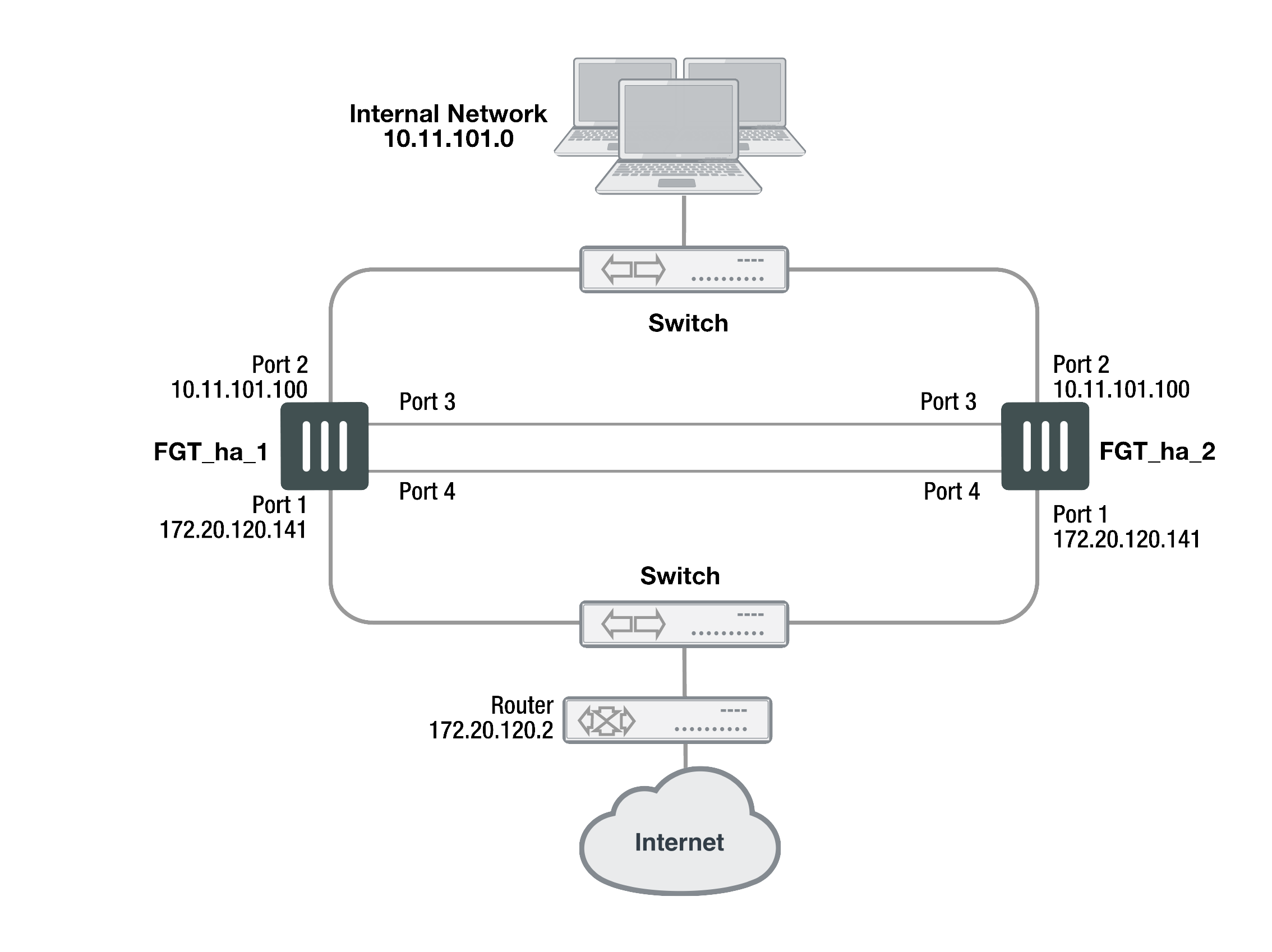
Port3 and port4 are used as the heartbeat interfaces. Because the cluster consists of two FortiGate units, you can make the connections between the heartbeat interfaces using crossover cables. You could also use switches and regular ethernet cables.
General configuration steps
The section includes web-based manager and CLI procedures. These procedures assume that the FortiGate units are running the same FortiOS firmware build and are set to the factory default configuration.
General configuration steps
- Apply licenses to the FortiGate units to become the cluster.
- Configure the FortiGate units for HA operation.
- Optionally change each unit’s host name.
- Configure HA.
- Connect the cluster to the network.
- Confirm that the cluster units are operating as a cluster and add basic configuration settings to the cluster.
- View cluster status from the web-based manager or CLI.
- Add a password for the admin administrative account.
- Change the IP addresses and netmasks of the internal and external interfaces.
- Add a default route.
Configuring a NAT/Route mode active-passive cluster of two FortiGate units - web-based manager
Use the following procedures to configure two FortiGate units for NAT/Route HA operation using the web-based manager. These procedures assume you are starting with two FortiGate units with factory default settings.
|
|
Give each cluster unit a unique host name to make the individual units easier to identify when they are part of a functioning cluster. The default host name is the FortiGate serial number. You may want to change this host name to something more meaningful for your network. |
To configure the first FortiGate unit (host name FGT_ha_1)
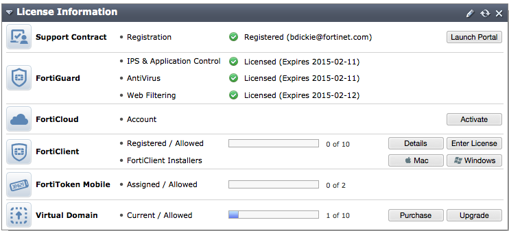
- Register and apply licenses to the FortiGate unit. This includes FortiCloud activation and FortiClient licensing and entering a license key if you purchased more than 10 Virtual Domains (VDOMS).
- You can also install any third-party certificates on the primary FortiGate before forming the cluster. Once the cluster is formed third-party certificates are synchronized to the backup FortiGate.
FortiToken licenses can be added at any time because they are synchronized to all cluster members. - On the System Information dashboard widget beside Host Name, select Change.
- Enter a new Host Name for this FortiGate unit.
| New Name | FGT_ha_1 |
- Select OK.
- Go to System > Config > HA and change the following settings:
| Mode | Active-Passive |
| Group Name | example1.com |
| Password | HA_pass_1 |
|
|
This is the minimum recommended configuration for an active-passive HA cluster. You can also configure other HA options, but if you wait until after the cluster is operating you will only have to configure these options once for the cluster instead of separately for each unit in the cluster. |
- Select OK.
The FortiGate unit negotiates to establish an HA cluster. When you select OK you may temporarily lose connectivity with the FortiGate unit as the HA cluster negotiates and the FGCP changes the MAC address of the FortiGate unit interfaces. The MAC addresses of the FortiGate interfaces change to the following virtual MAC addresses:
- port1 interface virtual MAC:
00-09-0f-09-00-00 - port2 interface virtual MAC:
00-09-0f-09-00-01 - port3 interface virtual MAC:
00-09-0f-09-00-02 - port4 interface virtual MAC:
00-09-0f-09-00-03
To reconnect sooner, you can update the ARP table of your management PC by deleting the ARP table entry for the FortiGate unit (or just deleting all arp table entries). You may be able to delete the arp table of your management PC from a command prompt using a command similar to
arp -d.To confirm these MAC address changes, you can use the
get hardware nic(ordiagnose hardware deviceinfo nic) CLI command to view the virtual MAC address of any FortiGate unit interface. For example, use the following command to view the port1 interface virtual MAC address (MAC) and the port1 permanent MAC address (Permanent_HWaddr):
get hardware nic port1
.
.
.
Current_HWaddr: 00:09:0f:09:00:00
Permanent_HWaddr 02:09:0f:78:18:c9
.
.
.
- Power off the first FortiGate unit (FGT_ha_1).
|
|
Note the details and format of the output of the get hardware nic command are specific to the interface hardware. Different FortiGate models and even different interfaces in the same FortiGate unit may have different output. |
To configure the second FortiGate unit (host name FGT_ha_2)
- Register and apply licenses to the FortiGate unit. This includes FortiCloud activation and FortiClient licensing, and entering a license key if you purchased more than 10 Virtual Domains (VDOMS).
- On the System Information dashboard widget, beside Host Name select Change.
- Enter a new Host Name for this FortiGate unit.
| New Name | FGT_ha_2 |
- Select OK.
- Go to System > Config > HA and change the following settings:
| Mode | Active-Passive |
| Group Name | example1.com |
| Password | HA_pass_1 |
- Select OK.
The FortiGate unit negotiates to establish an HA cluster. When you select OK you may temporarily lose connectivity with the FortiGate unit as the HA cluster negotiates and because the FGCP changes the MAC address of the FortiGate unit interfaces.
To reconnect sooner, you can update the ARP table of your management PC by deleting the ARP table entry for the FortiGate unit (or just deleting all arp table entries). You may be able to delete the arp table of your management PC from a command prompt using a command similar to
arp -d.
- Power off the second FortiGate unit.
To connect the cluster to the network
- Connect the port1 interfaces of FGT_ha_1 and FGT_ha_2 to a switch connected to the Internet.
- Connect the port2 interfaces of FGT_ha_1 and FGT_ha_2 to a switch connected to the internal network.
- Connect the port3 interfaces of FGT_ha_1 and FGT_ha_2 together. You can use a crossover Ethernet cable or regular Ethernet cables and a switch.
- Connect the port4 interfaces of the cluster units together. You can use a crossover Ethernet cable or regular Ethernet cables and a switch.
- Power on the cluster units.
The units start and negotiate to choose the primary unit and the subordinate unit. This negotiation occurs with no user intervention and normally takes less than a minute.
When negotiation is complete the cluster is ready to be configured for your network.
To view cluster status
Use the following steps to view the cluster dashboard and cluster members list to confirm that the cluster units are operating as a cluster.
|
|
Once the cluster is operating, because configuration changes are synchronized to all cluster units, configuring the cluster is the same as configuring an individual FortiGate unit. You could have performed the following configuration steps separately on each FortiGate unit before you connected them to form a cluster. |
- Start Internet Explorer and browse to the address https://192.168.1.99 (remember to include the “s” in https://).
The FortiGate Login is displayed. - Type
adminin the Name field and select Login.
The FortiGate dashboard is displayed.
The System Information dashboard widget shows the Cluster Name (example1.com) and the host names and serial numbers of the Cluster Members. The Unit Operation widget shows multiple cluster units.
- Go to System > Config > HA to view the cluster members list.
The list shows both cluster units, their host names, their roles in the cluster, and their device priorities. You can use this list to confirm that the cluster is operating normally. For example, if the list shows only one cluster unit then the other unit has left the cluster for some reason.
To troubleshoot the cluster configuration
If the cluster members list and the dashboard do not display information for both cluster units, the FortiGate units are not functioning as a cluster. See Setting up two new FortiGates as an FGCP cluster to troubleshoot the cluster.
To add basic configuration settings to the cluster
Use the following steps to configure the cluster to connect to its network. The following are example configuration steps only and do not represent all of the steps required to configure the cluster for a given network.
- Log into the cluster web-based manager.
- Go to System > Admin > Administrators.
- Edit admin and select Change Password.
- Enter and confirm a new password.
- Select OK.
- Go to System > Network > Interfaces.
- Edit the port2 interface and change IP/Netmask to 10.11.101.100/24.
- Select OK.
|
|
After changing the IP address of the port1 interface you may have to change the IP address of your management computer and then reconnect to the port1 interface using the 172.20.120.141 IP address. |
- Edit the port1 interface and change IP/Netmask to 172.20.120.141/24.
- Select OK.
- Go to Router > Static > Static Routes.
- Change the default route.
| Destination IP/Mask | 0.0.0.0/0.0.0.0 |
| Gateway | 172.20.120.2 |
| Device | port1 |
| Distance | 10 |
- Select OK.
Configuring a NAT/Route mode active-passive cluster of two FortiGate units - CLI
Use the following procedures to configure two FortiGate units for NAT/Route HA operation using the FortiGate CLI. These procedures assume you are starting with two FortiGate units with factory default settings.
To configure the first FortiGate unit (host name FGT_ha_1)
- Power on the FortiGate unit.
- Connect a null modem cable to the communications port of the management computer and to the FortiGate Console port.
- Start HyperTerminal (or any terminal emulation program), enter a name for the connection, and select OK.
- Configure HyperTerminal to connect directly to the communications port on the computer to which you have connected the null modem cable and select OK.
- Select the following port settings and select OK.
| Bits per second | 9600 |
| Data bits | 8 |
| Parity | None |
| Stop bits | 1 |
| Flow control | None |
- Press Enter to connect to the FortiGate CLI.
The FortiGate unit CLI login prompt appears.
If the prompt does not appear, press Enter. If it still does not appear, power off your FortiGate unit and power it back on. If you are connected, at this stage you will see startup messages that will confirm you are connected. The login prompt will appear after the startup has completed.
- Type
adminand press Enter twice. - Register and apply licenses to the FortiGate unit. This includes FortiCloud activation and FortiClient licensing, and entering a license key if you purchased more than 10 Virtual Domains (VDOMS).
- You can also install any third-party certificates on the primary FortiGate before forming the cluster. Once the cluster is formed third-party certificates are synchronized to the backup FortiGate.
FortiToken licenses can be added at any time because they are synchronized to all cluster members. - Change the host name for this FortiGate unit.
config system global
set hostname FGT_ha_1
end
- Configure HA settings.
config system ha
set mode a-p
set group-name example1.com
set password HA_pass_1
end
The FortiGate unit negotiates to establish an HA cluster. You may temporarily lose network connectivity with the FortiGate unit as the HA cluster negotiates and the FGCP changes the MAC address of the FortiGate unit interfaces. The MAC addresses of the FortiGate interfaces change to the following virtual MAC addresses:
- port1 interface virtual MAC:
00-09-0f-09-00-00 - port2 interface virtual MAC:
00-09-0f-09-00-01 - port3 interface virtual MAC:
00-09-0f-09-00-02 - port4 interface virtual MAC:
00-09-0f-09-00-03
To reconnect sooner, you can update the ARP table of your management PC by deleting the ARP table entry for the FortiGate unit (or just deleting all arp table entries). You may be able to delete the arp table of your management PC from a command prompt using a command similar to
arp -d.To confirm these MAC address changes, you can use the
get hardware nic(ordiagnose hardware deviceinfo nic) CLI command to view the virtual MAC address of any FortiGate unit interface. For example, use the following command to view the port1 interface virtual MAC address (MAC) and the port1 permanent MAC address (Permanent_HWaddr):
get hardware nic port1
.
.
.
Current_HAaddr 00:09:0f:09:00:00
Permanent_HWaddr 02:09:0f:78:18:c9
.
.
.
- Display the HA configuration (optional).
get system ha
group-id : 0
group-name : example1.com
mode : a-p
password : *
hbdev : "port3" 50 "port4" 50
session-sync-dev :
route-ttl : 10
route-wait : 0
route-hold : 10
sync-config : enable
encryption : disable
authentication : disable
hb-interval : 2
hb-lost-threshold : 20
helo-holddown : 20
arps : 5
arps-interval : 8
session-pickup : disable
update-all-session-timer: disable
session-sync-daemon-number: 1
link-failed-signal : disable
uninterruptible-upgrade: enable
ha-mgmt-status : disable
ha-eth-type : 8890
hc-eth-type : 8891
l2ep-eth-type : 8893
ha-uptime-diff-margin: 300
vcluster2 : disable
vcluster-id : 1
override : disable
priority : 128
slave-switch-standby: disable
minimum-worker-threshold: 1
monitor :
pingserver-monitor-interface:
pingserver-failover-threshold: 0
pingserver-slave-force-reset: enable
pingserver-flip-timeout: 60
vdom : "root"
- Power off the FortiGate unit.
To configure the second FortiGate unit (host name FGT_ha_2)
- Power on the FortiGate unit.
- Connect a null modem cable to the communications port of the management computer and to the FortiGate Console port.
- Start HyperTerminal, enter a name for the connection, and select OK.
- Configure HyperTerminal to connect directly to the communications port on the computer to which you have connected the null modem cable and select OK.
- Select the following port settings and select OK.
| Bits per second | 9600 |
| Data bits | 8 |
| Parity | None |
| Stop bits | 1 |
| Flow control | None |
- Press Enter to connect to the FortiGate CLI.
The FortiGate unit CLI login prompt appears. - Type
adminand press Enter twice. - Register and apply licenses to the FortiGate unit. This includes FortiCloud activationand FortiClient licensing, and entering a license key if you purchased more than 10 Virtual Domains (VDOMS).
- You can also install any third-party certificates on the primary FortiGate before forming the cluster. Once the cluster is formed third-party certificates are synchronized to the backup FortiGate.
FortiToken licenses can be added at any time because they are synchronized to all cluster members. - Change the host name for this FortiGate unit.
config system global
set hostname FGT_ha_2
end
- Configure HA settings.
config system ha
set mode a-p
set group-name example1.com
set password HA_pass_1
end
The FortiGate unit negotiates to establish an HA cluster. You may temporarily lose network connectivity with the FortiGate unit as the HA cluster negotiates and because the FGCP changes the MAC address of the FortiGate unit interfaces.
To reconnect sooner, you can update the ARP table of your management PC by deleting the ARP table entry for the FortiGate unit (or just deleting all arp table entries). You may be able to delete the arp table of your management PC from a command prompt using a command similar to
arp -d.
- Display the HA configuration (optional).
get system ha
group-id : 0
group-name : example1.com
mode : a-p
password : *
hbdev : "port3" 50 "port4" 50
session-sync-dev :
route-ttl : 10
route-wait : 0
route-hold : 10
sync-config : enable
encryption : disable
authentication : disable
hb-interval : 2
hb-lost-threshold : 20
helo-holddown : 20
arps : 5
arps-interval : 8
session-pickup : disable
update-all-session-timer: disable
session-sync-daemon-number: 1
link-failed-signal : disable
uninterruptible-upgrade: enable
ha-mgmt-status : disable
ha-eth-type : 8890
hc-eth-type : 8891
l2ep-eth-type : 8893
ha-uptime-diff-margin: 300
vcluster2 : disable
vcluster-id : 1
override : disable
priority : 128
slave-switch-standby: disable
minimum-worker-threshold: 1
monitor :
pingserver-monitor-interface:
pingserver-failover-threshold: 0
pingserver-slave-force-reset: enable
pingserver-flip-timeout: 60
vdom : "root"
- Power off the FortiGate unit.
To connect the cluster to the network
- Connect the port1 interfaces of FGT_ha_1 and FGT_ha_2 to a switch connected to the Internet.
- Connect the port2 interfaces of FGT_ha_1 and FGT_ha_2 to a switch connected to the internal network.
- Connect the port3 interfaces of FGT_ha_1 and FGT_ha_2 together. You can use a crossover Ethernet cable or regular Ethernet cables and a switch.
- Connect the port4 interfaces of the cluster units together. You can use a crossover Ethernet cable or regular Ethernet cables and a switch.
- Power on the cluster units.
The units start and negotiate to choose the primary unit and the subordinate unit. This negotiation occurs with no user intervention and normally takes less than a minute.
When negotiation is complete the cluster is ready to be configured for your network.
To view cluster status
Use the following steps to view cluster status from the CLI.
- Determine which cluster unit is the primary unit.
- Use the null-modem cable and serial connection to re-connect to the CLI of one of the cluster units.
- Enter the command
get system status. - If the command output includes
Current HA mode: a-p, master, the cluster units are operating as a cluster and you have connected to the primary unit. Continue with Step Setting up two new FortiGates as an FGCP cluster. - If the command output includes
Current HA mode: a-p, backup, you have connected to a subordinate unit. Connect the null-modem cable to the other cluster unit, which should be the primary unit and continue with Step 2.
|
|
If the command output includes Current HA mode: standalone, the cluster unit is not operating in HA mode and you should review your HA configuration. |
- Enter the following command to confirm the HA configuration of the cluster:
get system ha status
Model: XXXXX
Mode: a-p
Group: 0
Debug: 0
ses_pickup: disable
Master:128 FGT_ha_2 FG600B3908600825 0
Slave :128 FGT_ha_1 FG600B3908600705 1
number of vcluster: 1
vcluster 1: work 169.254.0.1
Master:0 FG600B3908600825
Slave :1 FG600B3908600705
The command output shows both cluster units, their host names, their roles in the cluster, and their priorities. You can use this command to confirm that the cluster is operating normally. For example, if the command shows only one cluster unit then the other unit has left the cluster for some reason.
- Check the cluster synchronization status to make sure the primary and backup units have the same configuration. Log into the primary unit CLI and enter this command:
diag sys ha cluster-csum
The CLI lists all members' checksums. If both cluster units have identical checksums you can be sure that their configurations are synchronized. If the checksums are different wait a short while and enter the command again. Repeat until the checksums are identical. It may take a while for some parts of the configuration to be synchronized. If the checksums never become identical contact Fortinet support to help troubleshoot the problem.
To troubleshoot the cluster configuration
If the cluster members list and the dashboard do not display information for both cluster units the FortiGate units are not functioning as a cluster. See Setting up two new FortiGates as an FGCP cluster to troubleshoot the cluster.
To add basic configuration settings to the cluster
Use the following steps to add some basic settings to the cluster so that it can connect to the network.
- Log into the primary unit CLI.
- Add a password for the admin administrative account.
config system admin
edit admin
set password <password_str>
end
- Configure the port1 and port2 interfaces.
config system interface
edit port1
set ip 172.20.120.141/24
next
edit port2
set ip 10.11.101.100/24
end
- Add a default route.
config router static
edit 1
set dst 0.0.0.0 0.0.0.0
set gateway 172.20.120.2
set device port1
end
Copyright © 2018 Fortinet, Inc. All Rights Reserved. | Terms of Service | Privacy Policy
