Configuring cameras
After you have connected the cameras to FortiRecorder, you can start to configure the discovered cameras. Because most of the camera information has been retrieved from the camera, you do not have to change the settings. But if you are adding a remote camera or adding a new camera before connecting it to FortiRecorder, you must specify all the camera settings.
1. Go to Camera > Configuration > Camera. For each discovered camera, click its row to select it, click Configure, then configure these settings:
Setting name | Description |
Enable | Mark this check box to enable the FortiRecorder NVR to communicate with this IP address. Communications are required to trigger scheduled recordings and other camera commands. |
Name | Type a name (such as front-door1) that can be referenced by other parts of the configuration. Do not use spaces or special characters. The maximum length is 35 characters. |
Location | Optional. Type a description of the camera’s physical location that can be used if the camera is hidden, in case it is forgotten or lost. |
Vendor/Camera | FortiRecorder supports Fortinet cameras (FortiCam series) and third-party, ONVIF-compliant cameras. If you are configuring a discovered camera, most of the camera information has been retrieved and displayed. You can also click the Camera detail button to refresh the camera information. If you are adding a remote camera, or adding a new camera before it is connected, you must specify all the settings. For the Fortinet FortiCam cameras, you must specify the models; for the non-Fortinet cameras, you must specify the camera’s login credentials (user name and password) for FortiRecorder to access it. |
Model | Select the name of the camera model, such as FCM-20A for a FortiCam 20A. |
Address mode | Select either: • Wired — Select this option if you want to keep the camera connected with the Ethernet cable on the same subnet. • Wireless — Select this option if you want to change the camera connection from wired to wireless. Also configure the WiFi settings on the WiFi tab. • VIP — Allow the camera to continue using DHCP to determine its IP address, but the camera will be on a remote network, and therefore the FortiRecorder NVR will not connect to the camera’s DHCP address. Instead, the NVR will connect through the static external, usually public network IP address and port numbers (called a virtual IP or VIP on FortiGate firewalls) specified in Address, (HTTPS) Port, and (RTSP) Port. The router or firewall will translate and forward connections to the camera’s private network address. Likewise, communications in the other direction — from the camera to the FortiRecorder NVR — are also affected: the camera will use the public IP setting as its destination (see “Configuring system timeout, ports, and public access”), not the private network address of port1, for example, which it would use if you select DHCP or Static. Tip: Use this option if the camera is not located on the same private network as the FortiRecorder NVR due to NAT/ port forwarding, especially if the camera and NVR are separated by the Internet. |
Address | If you want to deploy the camera to a different subnet, you can specify its new IP address or the VIP that it will be using. |
(HTTPS) Port | Type the port number of configuration communications from the FortiRecorder that the firewall or router will forward to the camera. If using only a WAN/virtual IP without port forwarding/translation, leave this setting at its default value, 443. This setting is available only when Address mode is set to VIP. |
(RTSP) Port | Type the port number of video streaming commands (RTSP) from the FortiRecorder that the firewall or router will forward to the camera, such as when beginning a continuous recording schedule. If using only a WAN/virtual IP without port forwarding/translation, leave this setting at its default value, 554. This setting is available only when Address mode is set to VIP. |
Transport Type | Normally RTSP is used for video streaming, which is UDP. If you want to use TCP, you can use HTTP tunnelling. If you want the communication to be secure/encrypted, you can use HTTPS tunnelling. The tunnel is between the camera and the NVR. |
Profile | Select the camera profile that indicates the recording schedule, video quality, and other settings that will be used by this camera (see “Connecting FortiRecorder to the cameras”). Or click New to create a new camera profile. |
2. Click the Preview button to retrieve a single still image from the camera. Then click Use As Icon to use the captured image as the icon for the camera in the camera list. When you select the camera from the list, the icon will pop up.
3. Depending on the camera model you are configuring, different tabs appear.
4. If the address mode is wired or wireless, under the network tab, configure the following:
Setting name | Description |
Wired settings | Select DHCP if you want the camera to continue using DHCP to dynamically determine its IP address. The FortiRecorder NVR will attempt to keep track of any DHCP-related IP address changes automatically using periodic mDNS probes. This requires that the camera remain on the same subnet as the NVR. Select Static to re-configure the camera with a static private network IP address that you specify in Address. It will no longer use DHCP. This option requires that the camera and NVR not be separated by NAT. Caution: It is strongly recommended to either: • configure your cameras with a static IP, or Without reservations, the IP address provided by the DHCP server may appear to work initially, but later, in some cases, the DHCP server could change the IP address lease. If this happens, the DHCP server will not update the list of known cameras with the camera’s new dynamic IP. Until the appliance discovers that the IP address has changed, FortiRecorder will still be trying to control the camera’s old address, which no longer works. Connections with that camera will be broken and all video from that camera will be lost during that interruption. |
Wireless settings | This area displays the wireless DHCP settings for the camera. You can change the camera to use a static IP address. For more information about wireless connection, see the following WiFi section. |
5. If the camera has wireless function and you want it to connect to FortiRecorder through a wireless router, you can specify the WiFi settings on the WiFi tab. After you configure the WiFi settings, you can disconnect the discovered camera and connect it to the router.
Setting name | Description |
Enable | Select to Enable the WiFi function of the camera. |
SSID | Specify the wireless router’s SSID that the camera will connect to. |
Security | Specify the security settings. |
6. If the camera supports infra red recording or LED lighting, configure the settings on the Light or Infrared tab.
Setting name | Description |
Mode | Either off or auto. Auto means to turn on infra red mode at the threshold. |
LED | Either off or auto. Auto means to turn on the LED lights when the infra red mode is turned on. |
Enable threshold | Enter the light level when infra red mode should turn on. |
Disable threshold | Enter the light level when infra red mode should turn off. |
Threshold time | Enter the time interval (in seconds) when the camera should wait to turn on or off the infra red mode after the threshold is reached. |
Current light level | Display the current light level that the camera detects. |
Refresh | Click to get instant light level reading. |
7. Configure the video and audio settings on the Video/Audio tab. Available setting vary on different camera models. If the setting is greyed out, the setting is not supported on the selected model.
Setting name | Description |
Horizontal flip | Enable if the camera is positioned looking at a mirror or on a ceiling, and the preview image appears to be reversed left to right. |
Vertical flip | Enable if the camera is positioned on a ceiling, and the preview image appears to be upside down. |
WDR | If the camera supports WDR (wide dynamic range), enable it if there is intense backlight in the camera view. |
Environment | Select if the camera is installed indoor or outdoor. |
View angle | Select the view angle if the camera support it. |
Get feed/Stop feed | Click to view or stop the live video feed. |
(Other settings) | Configure the brightness, contrast, saturation, sharpness, zoom level, and audio input level as required. |
8. In some cases, you may want to mask an area and do not want to show a certain portion of the image. For example, for privacy reason, you may want to mask the area where an employee sits. To do this, on the Privacy Mask tab, click the plus sign beside Mask Window and tweak the window size. To add another mask window, click the plus sign again.
9. All FortiCam cameras are capable of detecting motion. Some camera models also supports audio surveillance and digital input and output (DIDO).
By default, while using motion detection, cameras will be triggered to record if any motion occurs within their entire field of vision. If some parts of the view, such as a fan, traffic, or strobe light, would inadvertently trigger motion detection, in the Motion detection windows area on the Detection tab, click the plus sign. A rectangle with a thick, white border will appear over the preview image, indicating the area that will be monitored for movement. To resize it to your intended area, click and drag the edges of the rectangle. To move it, hold down the Shift key while you click and drag it. To add another motion detection area, click the plus sign again.
For audio detection and DIDO, configure the following settings:
Setting name | Description |
Audio Sensitivity | If the camera supports audio surveillance, specify the sensitivity level that the camera recording will be triggered. You may need to tweak the sensitivity level, for example, when there are some background noises. |
PIR Sensitivity | |
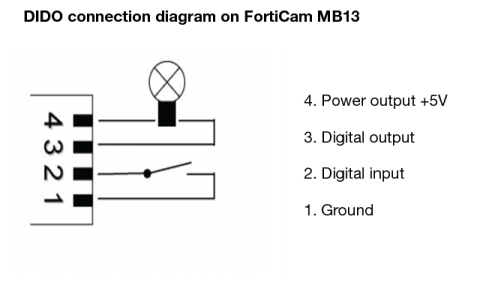
Digital input/output | Some cameras come with DIDO terminals and support digital input and output. For example, on the FortiCam MB13 camera, according to your configuration, power signal from the digital input can trigger the camera to record a video clip. You can also optionally connect other devices to the digital output, such as a relay to turn on/off another device. The digital input (DI) can be configured to trigger when the signal is: • LOW (ground) • HIGH (+5V) • Rising (transitioning from LOW to HIGH) • or Falling (transitioning from HIGH to LOW) If not connected, the camera will see the digital input as HIGH. The digital output (DO) can be configured to either be grounded or open when in the triggered state. When not triggered it will be in the opposite state. For example, if opening a door causes a sensor switch to open, then the switch could be wired between DI and ground. DI will be grounded (LOW) while the door is closed and will go HIGH when the door opens. DI could then be configured to trigger on the rising edge. When the door opens, DO would be set to its triggered state and a video clip will also be recorded. Triggering on the rising or falling edge can be useful if the DI might be held in the triggered state for a long period. In the example above, if DI were set to trigger on HIGH and the door is left open for a long period then the camera would trigger repeatedly. |
10. On the Miscellaneous tab, configure the following settings:
Setting name | Description |
Privacy button | FortiCam MB13 has a privacy button on it. If enabled, you can press the privacy button on the camera to stop and resume video and audio monitoring. To enable the functionality of the privacy button on the camera, select the Privacy button checkbox. To disable the functionality of the privacy button on the camera, clear the Privacy button checkbox. |
Status LEDs | Most cameras come with LED indicators (for details, see the LED description section in the camera’s QuickStart Guides). You can enable or disable the LEDs by selecting or deselecting the Status LEDS checkbox. |
11. Click OK.
If you kept the Enabled check box marked, at this time, FortiRecorder connects to the camera’s discovered IP address. FortiRecorder configures the camera with:
Afterwards, in order to control the camera according to your selected schedules, FortiRecorder will periodically connect to the camera’s configured IP address. It will also keep video recordings sent by that camera from its new IP address.
12. To confirm that FortiRecorder can receive video from the camera at its new IP address, go to Monitor > Video Monitor.
If no video is available from that camera, verify that:
• Other video software such as Windows Media Player or VLC has not stolen the RTSP file type association from QuickTime (Installing other video software after QuickTime is a common cause of changes to media file type associations.)
• A route exists to the camera’s new IP address and, if applicable, its virtual IP/port forward
To confirm, go to Monitor > System Status > Console and enter the command:
execute ping <camera_ipv4>
where <camera_ipv4> is the camera’s IP address or virtual IP/port forward. If you receive messages such as Timeout..., to locate the point of failure on the network, enter the command:
execute traceroute <camera_ipv4>
• Firewalls and routers, if any, allow both
RTSP and RTCP components of the RTP streaming video protocol between FortiRecorder and the camera
and between your computer and FortiRecorder (see
“Appendix A: Port numbers”)
• Web proxies or firewalls, if any, support streaming video
If you did not discover the camera but instead manually configured FortiRecorder with the camera’s IP address, confirm that the camera is actually located at that address.
13. If desired, you can specify different camera settings, such as brightness and contrast, for the camera to use as different times. For details, see
“Configuring schedules” on page 28.
See also