Configuring a bridge (V-zone)
You can configure a bridge either via the web UI or the CLI.
Bridges allow network connections to travel through the FortiWeb appliance’s physical network ports without explicitly connecting to one of its IP addresses. Due to this nature, bridges are configured only when FortiWeb is operating in either true transparent proxy or transparent inspection mode.
Bridges on the FortiWeb appliance support
IEEE 802.1d spanning tree protocol (STP) by forwarding bridge protocol data unit (BPDU) packets, but do
not generate BPDU packets of their own. Therefore, in some cases, you might need to manually test the bridged network for Layer 2 loops. Also, you may prefer to manually design a tree that uses the minimum cost path to the root switch for design and performance reasons.
True bridges typically have no IP address of their own. They use only media access control (MAC) addresses to describe the location of physical ports within the scope of their network and do network switching at Layer 2 of the OSI model.
To configure a bridge via the web UI
1. If you have installed a physical FortiWeb appliance, plug in network cables to connect one of the physical ports in the bridge to your protected web servers, and the other port to the Internet or your internal network.
Because port1 is reserved for connections with your management computer, for physical appliances, this means that you must plug cables into at least 3 physical ports:
• port1 to your management computer
• one port to your web servers
• one port to the Internet or your internal network
If you have installed a
virtual FortiWeb appliance (FortiWeb-VM), the number and topology of connections of your physical ports depend on your vNIC mappings. For details, see the
FortiWeb-VM Install Guide.
2. If you have installed FortiWeb-VM, configure the virtual switch (vSwitch). For details, see the
FortiWeb-VM Install Guide.
3. Go to System > Network > V-zone.
This option is not displayed if the current operating mode does not support bridges.
To access this part of the web UI, your administrator's account access profile must have
Read and
Write permission to items in the
Network Configuration category. For details, see
“Permissions”.
4. Click Create New.
A dialog appears.
| When you configure VLANs for a FortiWeb operating in true transparent proxy mode, ensure that you configure one V-zone for each VLAN. |
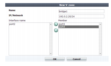
5. Configure these settings:
Setting name | Description |
Name | Type a unique name that can be referenced in other parts of the configuration. Do not use spaces or special characters. The maximum length is 15 characters. The name cannot be changed once you save the entry. See “Renaming entries”. |
IP/Netmask | Specify an IP address and subnet mask for the virtual network interface. Like non-bridge network interfaces, this IP address generates ARP traffic that notifies the network during an HA failover. For more information on HA failover, see “Configuring a high availability (HA) FortiWeb cluster”. Note: Failure to change the IP/Netmask will result in an Invalid IP Address error message. |
Interface name | Displays a list of network interfaces that currently have no IP address of their own, nor are members of another bridge, and therefore could be members of this bridge. To add one or more network interfaces to the bridge, select their names, then click the right arrow. Note: Only network interfaces with no IP address can belong to a bridge. port1 is reserved for your management computer, and cannot be bridged. To remove any other network interface’s IP address so that it can be included in the bridge, set its IP/Netmask to 0.0.0.0/0.0.0.0. |
Member | | Displays a list of network interfaces that belong to this bridge. To remove a network interface from the bridge, select its name, then click the left arrow. Tip: If you will be configuring bypass/fail-to-wire, the pair of bridge ports that you select should be ones that are wired together to support it. See “Fail-to-wire for power loss/reboots”. |
6. Click OK.
The bridge appears in System > Network > V-zone.
To configure an IPv4 bridge in the CLI
1. If you have installed a physical FortiWeb appliance, connect one of the physical ports in the bridge to your protected web servers, and the other port to the Internet or your internal network.
Because port1 is reserved for connections with your management computer, for physical appliances, this means that you must connect at least 3 ports:
• port1 to your management computer
• one port to your web servers
• one port to the Internet or your internal network
If you have installed a virtual FortiWeb appliance, the number and topology of connections of your physical ports depend on your vNIC mappings. For details, see the
FortiWeb-VM Install Guide.
2. If you have installed FortiWeb as a virtual appliance (FortiWeb-VM), configure the virtual switch. For details, see the
FortiWeb-VM Install Guide.
3. Enter the following commands:
config system v-zone
edit <v-zone_name>
set ip <address_ipv4> <netmask_ipv4>
set interfaces {<port_name> ...}
end
where:
• <v-zone_name> is the name of the bridge
• {<port_name> ...} is a space-delimited list of one or more network ports that will be members of this bridge. Eligible network ports must not yet belong to a bridge, and have no assigned IP address. For a list of eligible ports, enter:
set interfaces ?
• <address_ipv4> <netmask_ipv4> is an IP address for the bridge ports
See also