Partially-redundant route-based VPN example
This example demonstrates how to set up a partially redundant IPsec VPN between a local FortiGate unit and a remote VPN peer that receives a dynamic IP address from an ISP before it connects to the FortiGate unit. For more information about FortiGate dialup-client configurations, see
“FortiGate dialup-client configurations”.
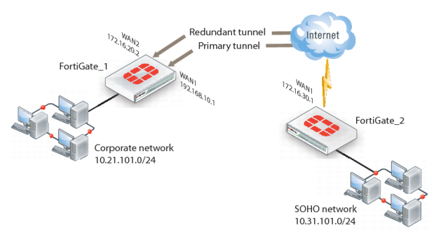
When a FortiGate unit has more than one interface to the Internet (see FortiGate_1 in
Figure 196), you can configure redundant routes. If the primary connection fails, the FortiGate unit can establish a VPN using the redundant connection.
In this case, FortiGate_2 has only one connection to the Internet. If the link to the ISP were to go down, the connection to FortiGate_1 would be lost, and the tunnel would be taken down. The tunnel is said to be partially redundant because FortiGate_2 does not support a redundant connection.
In the configuration example:
• Both FortiGate units operate in NAT mode.
• Two separate interfaces to the Internet (192.168.10.2 and 172.16.20.2) are available on FortiGate_1. Each interface has a static public IP address.
• FortiGate_2 has a single connection to the Internet and obtains a dynamic public IP address (for example, 172.16.30.1) when it connects to the Internet.
• FortiGate_2 forwards IP packets from the SOHO network (10.31.101.0/24) to the corporate network (10.21.101.0/24) behind FortiGate_1 through a partially redundant IPsec VPN. Encrypted packets from FortiGate_2 are addressed to the public interface of FortiGate_1. Encrypted packets from FortiGate_1 are addressed to the public IP address of FortiGate_2.
There are two possible paths for communication between the two units. In this example, these paths, listed in descending priority, are:
• FortiGate_1 WAN 1 to FortiGate_2 WAN 1
• FortiGate_1 WAN 2 to FortiGate_2 WAN 1
For each path, VPN configuration, security policies and routing are defined. By specifying a different routing distance for each path, the paths are prioritized. A VPN tunnel is established on each path, but only the highest priority one is used. If the highest priority path goes down, the traffic is automatically routed over the next highest priority path. You could use dynamic routing, but to keep this example simple, static routing is used.