Basic load balancing configuration example
This section describes the steps required to configure the load balancing configuration shown in
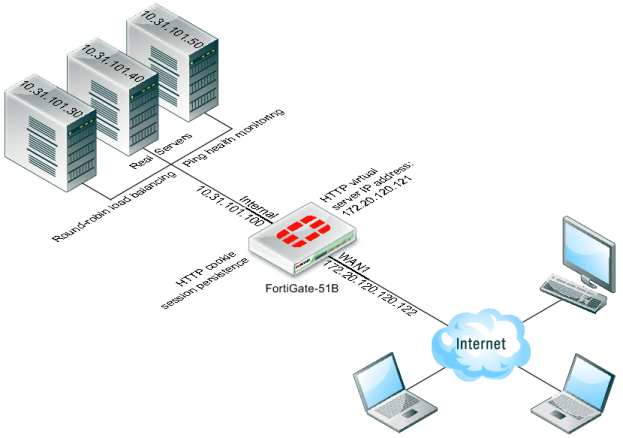
Figure 214. In this configuration a FortiGate-51B unit is load balancing HTTP traffic from the Internet to three HTTP servers on the Internal network. HTTP sessions are accepted at the wan1 interface with destination IP address 172.20.120.121 on TCP port 8080 and forwarded from the internal interface to the web servers. When forwarded the destination address of the sessions is translated to the IP address of one of the web servers.
The load balancing configuration also includes session persistence using HTTP cookies, round-robin load balancing, and TCP health monitoring for the real servers. Ping health monitoring consists of the FortiGate unit using ICMP ping to make sure the web servers can respond to network traffic.
Figure 214: Virtual server and real servers setup
To configure the example load balancing configuration - general configuration steps
1 Add a load balance ping health check monitor
A ping health check monitor causes the FortiGate unit to ping the real servers every 10 seconds. If one of the servers does not respond within 2 seconds, the FortiGate unit will retry the ping 3 times before assuming that the HTTP server is not responding.
2 Add a load balance virtual server.
3 Add the three load balance real servers. Include the virtual server in each real server configuration.
4 Add a security policy that includes the load balance virtual server as the destination address.
To configure the example load balancing configuration - web‑based manager
1 Go to go to Policy & Objects > Load Balance > Health Check and add the following health check monitor.
Name | Ping-mon-1 |
Type | Ping |
Interval | 10 seconds |
Timeout | 2 seconds |
Retry | 3 |
2 Go to Policy & Objects > Load Balance > Virtual Servers and add virtual server that accepts the traffic to be load balanced.
Name | Vserver-HTTP-1 |
Type | HTTP |
Interface | wan1 |
Virtual Server IP | 172.20.120.121 |
Virtual Server Port | 8080 |
Load Balance Method | Round Robin |
Persistence | HTTP Cookie |
HTTP Multiplexing | Do not select |
Health Check | Move Ping-mon-1 to the Selected list. |
3 Go to go to Policy & Objects > Load Balance > Real Servers and add the real servers.
Virtual Server | Vserver-HTTP-1 |
IP Address | 10.31.101.30 |
Port | 80 |
Weight | n/a |
Max Connections | 0 |
Mode | Active |
Virtual Server | Vserver-HTTP-1 |
IP Address | 10.31.101.40 |
Port | 80 |
Weight | n/a |
Max Connections | 0 |
Mode | Active |
Virtual Server | Vserver-HTTP-1 |
IP Address | 10.31.101.50 |
Port | 80 |
Weight | n/a |
Max Connections | 0 |
Mode | Active |
4 Go to Policy & Objects > Policy > IPv4 and add a wan1 to internal security policy that includes the virtual server. This policy also applies an Antivirus profile to the load balanced sessions.
Incoming Interface | wan1 |
Source Address | all |
Outgoing Interface | internal |
Destination Address | Vserver-HTTP-1 |
Schedule | always |
Service | ALL |
Action | ACCEPT |
NAT | Turn on NAT and select Use Destination Interface Address. |
Antivirus | Turn ON and select an Antivirus profile. |
5. Select OK.
To configure the example load balancing configuration- CLI
1 Use the following command to add a Ping health check monitor.
config firewall ldb-monitor
edit ping-mon-l
set type ping
set interval 10
set timeout 2
set retry 3
end
2 Use the following command to add the virtual server that accepts HTTP sessions on port 8080 at the wan1 interface and load balances the traffic to three real servers.
config firewall vip
edit Vserver-HTTP-1
set type server-load-balance
set server-type http
set ldb-method round-robin
set extip 172.20.120.30
set extintf wan1
set extport 8080
set persistence http-cookie
set monitor tcp-mon-1
config realservers
edit 1
set ip 10.31.101.30
set port 80
next
edit 2
set ip 10.31.101.40
set port 80
end
end
3 Use the following command to add a security policy that includes the load balance virtual server as the destination address.
config firewall policy
edit 0
set srcintf wan1
set srcaddr all
set dstintf internal
set dstaddr Vserver-HTTP-1
set action accept
set schedule always
set service ALL
set nat enable
set utm-status enable
set profile-protocol-options default
set av-profile scan
end