Example network topology
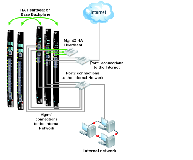
Figure 150 shows an HA cluster consisting of three FortiGate‑5001C cluster units (host names slot-3, slot-4, and slot-5) installed in a FortiGate-5000 series chassis with two FortiSwitch-5003B units for heartbeat communication between the cluster units. The cluster applies security features including FortiClient profiles to data traffic passing through it.
The cluster is managed from the internal network using the FortiGate-5001C mgmt1 interfaces configured as HA reserved management interfaces. Using these reserved management interfaces the overall cluster can be managed and cluster units can be managed individually. Individual management access to each cluster unit makes some operations, such as installing FortiClient licenses, easier and also allows you to view status of each cluster unit.
The reserved management interface of each cluster unit has a different IP address and retains its own MAC address. The cluster does not change the reserved management interface MAC address.
By default base1 and base2 are used for heartbeat communication between the FortiGate units. To use the base1 and base2 interfaces for the HA heartbeat, the example describes how to display the backplane interfaces on the web‑based manager before turning on HA.
This example also includes using the mgmt2 interface for heartbeat communication for additional heartbeat redundancy.
To connect the cluster
1. Connect the FortiGate-5001C port1 interfaces to a switch and connect that switch to the Internet.
2. Connect the FortiGate-5001C port2 interfaces to a switch and connect that switch to the internal network.
3. Connect the FortiGate-5001C mgmt1 interfaces to a switch that connects to the engineering network.
4. Connect the FortiGate-5001C mgmt2 interfaces to a switch for heartbeat communication between them.