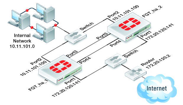
Figure 148 shows a typical FortiGate HA cluster consisting of two FortiGate units (FGT_ha_1 and FGT_ha_2) connected to the same internal (port2) and external (port1) networks.
Port3 and port4 are used as the heartbeat interfaces. Because the cluster consists of two FortiGate units, you can make the connections between the heartbeat interfaces using crossover cables. You could also use switches and regular ethernet cables.