SIP with a FortiGate unit
Depending on your security requirements and network configuration FortiGate units may be in many different places in a SIP configuration. This section shows a few examples.
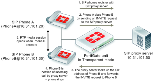
Figure 284 shows a FortiGate unit installed between a SIP proxy server and SIP phones on the same network. The FortiGate unit is operating in Transparent mode so both the proxy server and the phones are on the same subnet. In this configuration, called SIP inspection without address translation, the FortiGate unit could be protecting the SIP proxy server on the private network by implementing SIP security features for SIP sessions between the SIP phones and the SIP proxy server.
The phones and server use the same SIP dialogs as they would if the FortiGate unit was not present. However, the FortiGate unit can be configured to control which devices on the network can connect to the SIP proxy server and can also protect the SIP proxy server from SIP vulnerabilities.
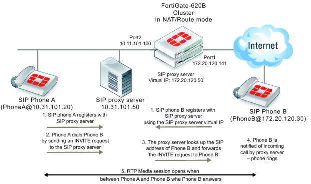
Figure 285 shows a FortiGate unit operating in NAT/Route mode and installed between a private network and the Internet. Some SIP phones and the SIP proxy server are connected to the private network and some SIP phones are connected to the Internet. The SIP phones on the Internet can connect to the SIP proxy server through the FortiGate unit and communication between SIP phones on the private network and SIP phones on the Internet must pass through the FortiGate unit.
The phones and server use the same SIP dialog as they would if the FortiGate unit was not present. However, the FortiGate unit can be configured to control which devices on the network can connect to the SIP proxy server and can also protect the SIP proxy server from SIP vulnerabilities. In addition, the FortiGate unit has a firewall virtual IP that forwards packets sent to the SIP proxy server Internet IP address (172.20.120.50) to the SIP proxy server internal network IP address (10.31.101.30).
Since the FortiGate unit is operating in NAT/Route mode it must translate packet source and destination IP addresses (and optionally ports) as the sessions pass through the FortiGate unit. Also, the FortiGate unit must translate the addresses contained in the SIP headers and SDP body of the SIP messages. As well the FortiGate unit must open SIP and RTP pinholes through the FortiGate unit. SIP pinholes allow SIP signalling sessions to pass through the FortiGate between phones and between phones and SIP servers. RTP pinholes allow direct RTP communication between the SIP phones once the SIP dialog has established the SIP call. Pinholes are opened automatically by the FortiGate unit. Administrators do not add security policies for pinholes or for RTP sessions. All that is required is a security policy that accepts SIP traffic.
Opening an RTP pinhole means opening a port on a FortiGate interface to allow RTP traffic to use that port to pass through the FortiGate unit between the SIP phones on the Internet and SIP phones on the internal network. A pinhole only accepts packets from one RTP session. Since a SIP call involves at least two media streams (one from Phone A to Phone B and one from Phone B to Phone A) the FortiGate unit opens two RTP pinholes. Phone A sends RTP packets through a pinhole in port2 and Phone B sends RTP packets through a pinhole in port1. The FortiGate unit opens the pinholes when required by the SIP dialog and closes the pinholes when the SIP call is completed. The FortiGate unit opens new pinholes for each SIP call.
Each RTP pinhole actually includes two port numbers. The RTP port number as defined in the SIP message and an RTCP port number, which is the RTP port number plus 1. For example, if the SIP call used RTP port 3346 the FortiGate unit would create a pinhole for ports 3346 and 3347.