Example of VLANs in transparent mode
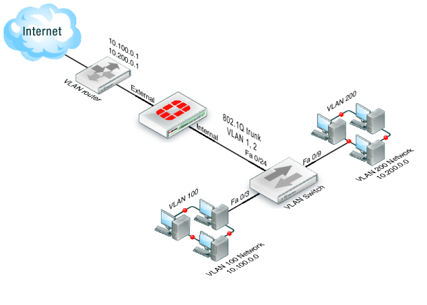
In this example, the FortiGate unit is operating in transparent mode and is configured with two VLANs: one with an ID of 100 and the other with ID 200. The internal and external physical interfaces each have two VLAN subinterfaces, one for VLAN_100 and one for VLAN_200.
The IP range for the internal VLAN_100 network is 10.100.0.0/255.255.0.0, and for the internal VLAN_200 network is 10.200.0.0/255.255.0.0.
The internal networks are connected to a Cisco 2950 VLAN switch, which combines traffic from the two VLANs onto one the FortiGate unit internal interface. The VLAN traffic leaves the FortiGate unit on the external network interface, goes on to the VLAN switch, and on to the Internet. When the FortiGate units receives a tagged packet, it directs it from the incoming VLAN subinterface to the outgoing VLAN subinterface for that VLAN.
This section describes how to configure a FortiGate-800 unit, Cisco switch, and Cisco router in the network topology shown in Figure 180.
See Also