External bypass
FortiDDoS can be deployed with an external bypass mechanism, such as a bypass switch. When both the FortiDDoS appliance and the failover switch share the same power supply, external connectivity is maintained during a power failure.
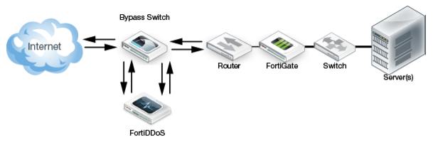
Figure 137 shows a bypass deployment when bypass is not active. The inline traffic flows through the FortiDDoS appliance.
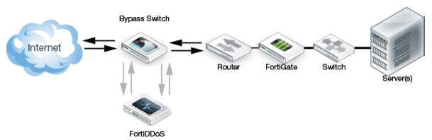
Figure 138 shows a bypass deployment when bypass is active. All inline traffic is routed through the switch until FortiDDoS is back online.
Either the automatic bypass mechanism or a bypass switch can maintain data traffic when there is a power or appliance failure. However, it is recommended that you automate failover behavior using a bypass switch with heartbeat. A bypass switch with heartbeat detects the failure of the FortiDDoS appliance (and the failure of traffic monitoring and mitigation) even when the appliance maintains the copper-based data link.
Using an optical bypass switch
Fortinet recommends FortiBridge optical bypass switches. Contact your Sales Engineer for recommendations on the models and features that best fit your FortiDDoS deployment.
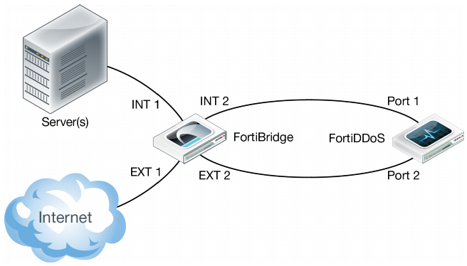
Figure 139 shows a deployment with an optical bypass switch that monitors the link to the attached FortiDDoS appliance by sending a heartbeat packet to the appliance once every second. If the optical bypass switch does not receive the heartbeat back, it automatically switches network traffic to bypass the unresponsive FortiDDoS appliance, even if the appliance is still receiving power. The optical bypass continues to send the heartbeat and restores the traffic through the FortiDDoS appliance as soon as the link is restored.
Configuring the optical bypass switch
• Input timeout period
• Input retry count
Connecting the optical bypass switch to the network and FortiDDoS
1. Connect the INT 1 port to the Ethernet segment.
2. Connect the EXT 1 port to the Internet side.
3. Connect the INT 2 port to the FortiDDoS server port (for example, Port 1).
4. Connect the EXT 2 port to the FortiDDoS Internet port (for example, Port 2).
Configuring MAC addresses for bypass switch heartbeat packets
When a FortiDDoS appliance is used in conjunction with a bypass switch such as FortiBridge, ensure that FortiDDoS allows heartbeat packets from the bypass switch in all possible cases.
Typical bypass switches use heartbeat packets to check if the data path is connected. If the data path is broken for some critical reason, the bypass switch switches to bypass mode from normal mode.
To ensure that it passes on the heartbeat packets, FortiDDoS allows you to specify the MAC addresses that the bypass switch uses for the packets.
You can view these MAC addresses in the FortiBridge status page.
Every FortiDDoS link pair can be connected via a FortiBridge link pair. For example, you can use a FortiBridge link to bridge the Port 1/Port 2 link pair and another FortiBridge link to bridge the Port 3/Port 4 link pair. Each link pair is associated with a pair of MAC addresses. Therefore, if you are using two links, you configure four MAC addresses. If you are using one link, specify two MAC addresses.
You can program up to 16 MAC addresses.
If the bypass switches are from the same vendor, the most significant 24-bits of their MAC addresses are the same.
To configure bypass MAC addresses:
1. Go to Global Settings > Bypass MAC > Bypass MAC.
2. Click Add, and then enter a name for the MAC address and the address.
3. Save the configuration.