Using source pools
This topic includes a procedure for configuring the source IP address pools used in NAT, and examples of NAT deployments. It includes the following sections:
Configuring source pools
You use the Source Pool page to create configuration objects for source IP addresses used for NAT in Layer 4 virtual server configurations.
In a Layer 4 virtual server configuration, you select a “packet forwarding method” that includes the following network address translation (NAT) options:
• Direct Routing—Does not rewrite source or destination IP addresses.
• DNAT—Rewrites the destination IP address for packets before it forwards them.
• Full NAT—Rewrites both the source and destination IP addresses. Use for standard NAT, when client and server IP addresses are all IPv4 or all IPv6.
• NAT46—Rewrites both the source and destination IP addresses. Use for NAT 46, when client IP addresses are IPv4 and server IP addresses are IPv6.
• NAT64—Rewrites both the source and destination IP addresses. Use for NAT 64, when client IP addresses are IPv6 and server IP addresses are IPv4.
In a Layer 7 virtual server configuration, you do not select a packet forwarding option. Layer 7 virtual servers use NAT46 and NAT64 to support those traffic flows, but they do not use the Source Pool configuration.
See the examples that follow the procedure for illustrated usage.
Before you begin:
• You must have a good understanding of NAT. You must know the address ranges your network has provisioned for NAT.
• Be sure to configure the backend servers to use the FortiADC address as the default gateway so that server responses are also rewritten by the NAT module.
• You must have Read-Write permission for Load Balance settings.
After you have configured a source pool IP address range configuration object, you can select it in the virtual server configuration.
To configure a source pool:
1. Go to Server Load Balance > Virtual Server.
2. Click the Source Pool tab.
3. Click Add to display the configuration editor.
4. Complete the configuration as described in
Table 18.
5. Save the configuration.
Table 18: Source pool configuration
Settings | Guidelines |
Name | Configuration name. Valid characters are A-Z, a-z, 0-9, _, and -. No spaces. You reference this name in the virtual server configuration. Note: After you initially save the configuration, you cannot edit the name. |
Interface | Interface to receive responses from the backend server. The interface used for the initial client traffic is determined by the virtual server configuration. |
Address Type | • IPv4 • IPv6 |
Address Range | The first address in the address pool. |
To | The last address in the address pool. |
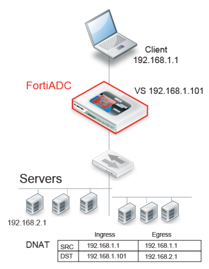
Example: DNAT
Figure 34 illustrates destination NAT (DNAT). The NAT module rewrites only the destination IP address. Therefore, if you configure destination NAT, you do not need to configure a source pool. In this DNAT example, the destination IP address in the packets it receives from the client request is the IP address of the virtual server—192.168.1.101. The NAT module translates this address to the address of the real server selected by the load balancer—in this example, 192.168.2.1. The system maintains this NAT table and performs the inverse translation when it receives the server-to-client traffic.
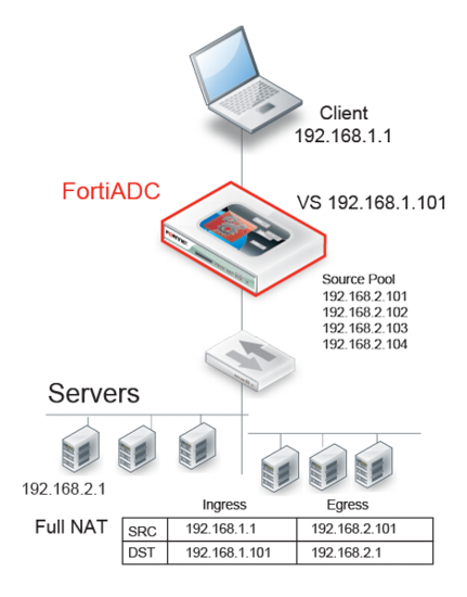
Example: full NAT
Figure 35 illustrates full NAT. The source IP / destination IP pair in the packets received is SRC 192.168.1.1 / DST 192.168.1.101. The NAT module translates the source IP address to the next available address in the source pool—in this example, 192.168.2.101. It translates the destination IP address to the address of the real server selected by the load balancer—in this example, 192.168.2.1.
The system maintains this NAT table and performs the inverse translation when it receives the server-to-client traffic.
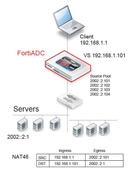
Example: NAT46 (Layer 4 virtual servers)
Figure 36 illustrates full NAT with NAT46. The IPv6 client connects to the virtual server IPv4 address. The source IP / destination IP pair in the packets received is SRC 192.168.1.1 / DST 192.168.1.101. The NAT module translates the source IP address to the next available IPv6 address in the source pool—in this example, 2002::2:1001. It translates the destination IP address to the IPv6 address of the real server selected by the load balancer—in this example, 2002::2:1.
The system maintains this NAT table and performs the inverse translation when it receives the server-to-client traffic.
Table 19: Limitations: NAT46 (Layer 4 virtual servers)
Features | Notes |
Profile | Not Supported: FTP |
ICMP | ICMP traffic is dropped. |
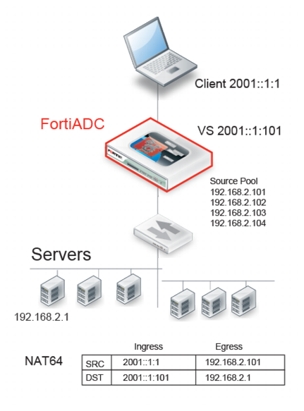
Example: NAT64 (Layer 4 virtual servers)
Figure 37 illustrates full NAT with NAT64. The IPv6 client connects to the virtual server IPv6 address. The source IP / destination IP pair in the packets received is SRC 2001::1:1 / DST 2001::1:101. The NAT module translates the source IP address to the next available IPv4 address in the source pool—in this example, 192.168.2.101. It translates the destination IP address to the IPv4 address of the real server selected by the load balancer—in this example, 192.168.2.1.
The system maintains this NAT table and performs the inverse translation when it receives the server-to-client traffic.
Table 20: Limitations: NAT64 (Layer 4 virtual servers)
Features | Notes |
Profiles | Not Supported: FTP |
ICMP | ICMP traffic is dropped. |
Security | Not Supported: IP Reputation, DoS protection, Security logs and reports |
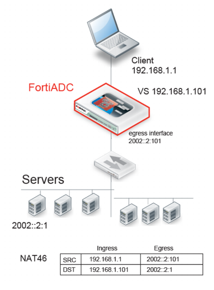
Example: NAT46 (Layer 7 virtual servers)
Figure 38 illustrates full NAT with NAT46. The IPv4 client connects to the virtual server IPv4 address. The source IP / destination IP pair in the packets received is SRC 192.168.1.1 / DST 192.168.1.101. The NAT module translates the source IP address to the IPv6 address of the egress interface that has IPv6 connectivity with the real server—in this example, 2002::2:1001. It translates the destination IP address to the IPv6 address of the real server selected by the load balancer—in this example, 2002::2:1.
The system maintains this NAT table and performs the inverse translation when it receives the server-to-client traffic.
Table 21: Limitations: NAT46 (Layer 7 virtual servers)
Feature | Note |
Profiles | Not Supported: RADIUS, HTTP Turbo |
Profile options | Not supported: Source Address (Using the original source IP address for the connection to the real server is contrary to the purpose of NAT.) |
Virtual server options | Not supported: Connection Rate Limit |
Real server pool options | Not supported: Connection Rate Limit |
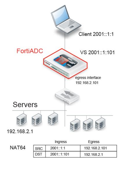
Example: NAT64 (Layer 7 virtual servers)
Figure 39 illustrates full NAT with NAT64. The IPv6 client connects to the virtual server IPv6 address. The source IP / destination IP pair in the packets received is SRC 2001::1:1 / DST 2001::1:101. The NAT module translates the source IP address to the IPv4 address of the egress interface that has IPv4 connectivity with the real server—in this example, 192.168.2.101. It translates the destination IP address to the IPv4 address of the real server selected by the load balancer—in this example, 192.168.2.1.
The system maintains this NAT table and performs the inverse translation when it receives the server-to-client traffic.
Table 22: Limitations: NAT64 (Layer 7 virtual servers)
Feature | Note |
Profiles | Not Supported: RADIUS, HTTP Turbo |
Profile options | Not supported: Source Address (Using the original source IP address for the connection to the real server is contrary to the purpose of NAT.) |
Virtual server options | Not supported: Connection Rate Limit |
Real server pool options | Not supported: Connection Rate Limit |
Security | Not Supported: IP Reputation, DoS protection, Security logs and reports |