Deploying an active-passive cluster
This topic includes the following information:
Overview
In an active-passive cluster, one node is the active appliance; it processes traffic. The other node is passive; it stands by to assume the role of the active appliance if the primary node is unavailable.
Figure 51 shows an active-passive cluster.
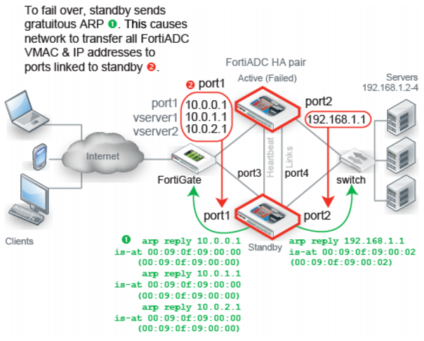
You configure the system to send heartbeat packets between the pair to monitor availability. The system continually polls the activity of the heartbeat packets. If the active appliance becomes unresponsive, failover occurs: the standby becomes active. It takes the IP addresses of the unresponsive node and notifies the network via ARP to redirect traffic for that virtual MAC address (vMAC) to its own network interfaces.
When the former active appliance comes back online, it might or might not assume its former active role. The system selects the active member based on the following criteria:
• Override setting
• Most available ports
• Highest uptime value
• Lowest device priority number (1 has greater priority than 2)
• Highest-sorting serial number—Serial numbers are sorted by comparing each character from left to right, where 9 and z are the greatest values. The system gives preference to higher values over lower values.
Basic steps
To deploy an active-passive cluster:
1. License all FortiADC appliances in the HA cluster, and register them, including FortiGuard services, with the Fortinet Technical Support web site:
2. Physically link the FortiADC appliances that make up the HA cluster.
You must link at least one of their ports (for example, port4 to port4) for heartbeat and synchronization traffic between members of the cluster. You can do either of the following:
• Connect the two appliances directly with a crossover cable.
• Link the appliances through a switch. If connected through a switch, the heartbeat interfaces must be reachable by Layer 2 multicast.
3. Configure the secondary node:
a. Log into the secondary appliance as the admin user.
Important: Set the Device Priority to a higher number than the primary appliance; for example, set Device Priority to 2.
4. Configure the primary node:
a. Log into the primary appliance as the admin user.
b. Complete the configuration for all features, as well as the HA configuration.
Important: Set the Device Priority to a lower number than the secondary appliance; for example, set Device Priority to 1.
Note: After you have saved the HA configuration changes, cluster members might join or rejoin the cluster. After you have save configuration changes on the primary node, it automatically pushes its configuration to the secondary node.
Best practice tips
The following tips are best practices:
• Be careful to maintain the heartbeat link(s). If the heartbeat is accidentally interrupted, such as when a network cable is temporarily disconnected, the other nodes assume that the primary node has failed. In an active-passive deployment, failover occurs. If no failure has actually occurred, both nodes can be operating as the active node simultaneously.
• If you link HA appliances through switches, to improve fault tolerance and reliability, link the ports through two separate switches. Also, do not connect these switches to your overall network, which could introduce a potential attack point, and could also allow network load to cause latency in the heartbeat, which could cause an unintentional failover.