To receive traffic intended for web servers that your FortiWeb appliance will protect, you usually must install the FortiWeb appliance between the web servers and all clients that access them.
The network configuration should make sure that all network traffic destined for the web servers must first pass to or through the FortiWeb appliance (depending on your operation mode). Usually, clients access web servers from the Internet through a firewall such as a FortiGate, so the FortiWeb appliance should be installed between the web servers and the firewall.
Other topology details and features vary by the mode in which the FortiWeb appliance will operate. For example, FortiWeb appliances operating in offline protection mode or either of the transparent modes cannot do network address translation (NAT) or load-balancing; FortiWeb appliances operating in reverse proxy mode can.
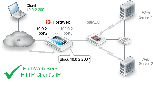
Usually you should deploy FortiWeb in front of your load balancer (such as FortiBalancer, FortiADC, or any other device that applies source NAT), so that FortiWeb is between the load balancer and the clients. This has important effects:
Otherwise, attackers’ and legitimate clients’ IP addresses may be hidden by the load balancer.
|
|
Alternatively, depending on the features that you require, you may be able to use FortiWeb’s built-in load balancing features instead. See Load Balancing Algorithm. |
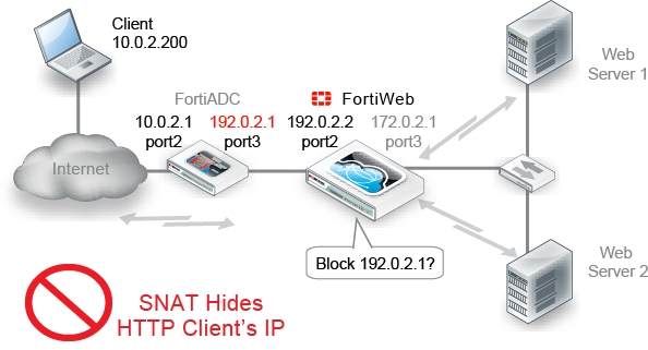
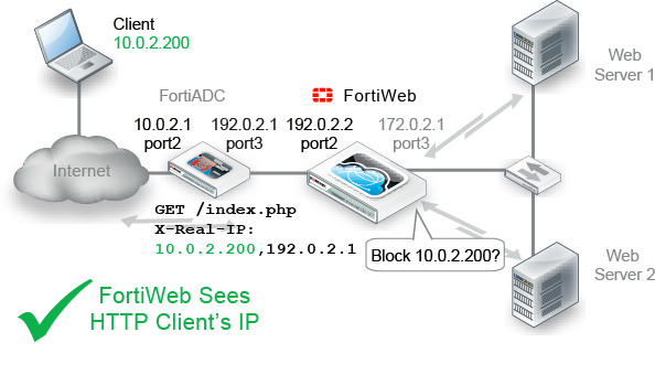
To prevent that, you must configure your devices to compensate for that topology if FortiWeb is behind your load balancer:
FortiWeb often applies blocking at the TCP/IP connection level, which could result in blocking innocent HTTP requests if the load balancer is transmitting them within the same TCP connection as an attack. It could therefore appear to cause intermittent failed requests.
X-Forwarded-For:, X-Real-IP:, or other HTTP X-header. Also configure FortiWeb to find the original attacker’s or client’s IP address in that HTTP header, not in the IP session (see Defining your proxies, clients, & X-headers). |
|
Some features do not support using client IPs found in the X-header. See Defining your proxies, clients, & X-headers. |
Many things, including:
vary by the operation mode. Choose the mode that best matches what you and your customers need. Considerations are discussed in Supported features in each operation mode and Matching topology with operation mode & HA mode.
Because this is such a pivotal factor, consider the implications carefully before you make your choice. It can be time-consuming to reconfigure your network if you switch modes later.
|
|
If you are not sure which operation mode is best for you, you can deploy in offline protection mode temporarily. This will allow you to implement some features and gather auto-learning data while you decide. |
Many features work regardless of the operation mode that you choose. For some features, support varies by the operation mode and, in some cases, varies by HTTP or HTTPS protocol. SSL/TLS, for example, inherently requires HTTPS. Similarly, rewriting inherently requires an inline topology and synchronous processing, and therefore is only supported in modes that work that way.
For the broadest feature support, choose reverse proxy mode.
If you require a feature that is not supported in your chosen operation mode, such as DoS protection or SSL/TLS offloading, your web server or another network appliance will need to be configured to provide that feature. The table below lists the features that are not universally supported in all modes/protocols.
| Feature | Operation mode | ||||
|---|---|---|---|---|---|
| Reverse proxy | True transparent proxy | Transparent inspection | Offline protection | ||
| HTTP | HTTPS | ||||
| Bridges / V-zones | No | Yes | Yes | Yes | No |
| Caching | Yes | Yes | Yes | No | No |
| Client Certificate Verification | Yes | Yes | Yes | No | No |
| Config. Sync (Non-HA) |
Yes ^ | Yes | Yes | Yes | Yes |
| Cookie Poisoning Prevention | Yes | Yes | Yes | No | No |
| DoS Protection | Yes | Yes | Yes | No | No |
| Error Page Customization | Yes | Yes | Yes | No | No |
| Fail-to-wire | No | Yes | Yes | Yes | No |
| File Compression | Yes | Yes | Yes | No | No |
| Hidden Input Constraints | Yes | Yes | Yes | No | No |
| HA | Yes | Yes | Yes | Yes | No |
| Information Disclosure Prevention (Anti-Server Fingerprinting) |
Yes | Yes | Yes | Yes § | Yes |
| Page Order Rules | Yes | Yes | Yes | No | No |
| Rewriting / Redirection | Yes | Yes | Yes | No | No |
| Session Management | Yes | Yes * | Yes * | Yes * | Yes * |
| Site Publishing | Yes | Yes | Yes | No | No |
| SSL/TLS Offloading | Yes | N/A | No | No | No |
| SSLv3 Support | Yes | N/A | Yes ~ | Yes ~¶ | Yes ~¶ |
| SSLv2 Support | Yes | N/A | No | No | No |
| Start Page Enforcement | Yes | Yes | Yes | No | No |
| User Authentication | Yes | Yes # | Yes | No | No |
| X-Forwarded-For: Support | Yes | Yes | Yes | No | No |
| ^ Full configuration sync is not supported in reverse proxy mode. § Only the Alert action is supported. * Requires that your web application have session IDs. See Session Key. ~ DSA-encrypted server certificates are not supported. ¶ Diffie-Hellman key exchanges are not supported. # PKI authentication requires HTTPS. |
|||||
Required physical topology varies by your choice of operation mode. It also varies depending on whether you will operate a high availability (HA) cluster of FortiWeb appliances. You may need to consider 1 or 2 of the next sections:
This is the default operation mode, and the most common. Most features are supported (see Supported features in each operation mode).
Requests are destined for a virtual server’s network interface and IP address on FortiWeb, not a web server directly. FortiWeb usually applies full NAT.
FortiWeb applies the first applicable policy, then forwards permitted traffic to a web server. FortiWeb logs, blocks, or modifies violations according to the matching policy.
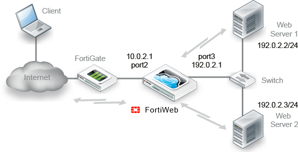
Example network topology: reverse proxy mode shows an example network topology for reverse proxy mode. A client accesses two web servers over the Internet through a FortiWeb appliance. A firewall is installed between FortiWeb and the Internet to regulate non-HTTP/HTTPS traffic. Port1 is connected to the administrator’s computer. Port2 is connected to the firewall. Port3 is connected to a switch, which is connected to the web servers. The FortiWeb appliance provides load-balancing between the two web servers.
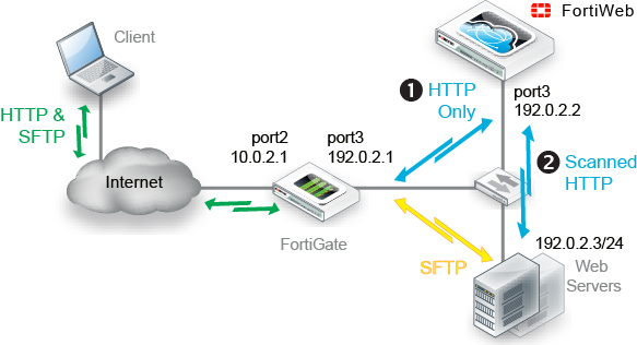
Alternatively, Example network topology: one-arm with reverse proxy mode shows multiple protocols originating from the client. Only HTTP/HTTPS is routed through FortiWeb for additional scanning and processing before arriving at the servers.
|
|
By default when in reverse proxy mode, FortiWeb will not forward non-HTTP/HTTPS traffic to from virtual servers to your protected back-end servers. (IP-based forwarding/routing of unscanned protocols is disabled.) If you must forward FTP, SSH, or other protocols to your back-end servers, Fortinet recommends that you do not deploy FortiWeb inline. Instead, use FortiGate VIP port forwarding to scan then send FTP, SSH, etc. protocols directly to the servers, bypassing FortiWeb. Deploy FortiWeb in a one-arm topology where FortiWeb receives only HTTP/HTTPS from the FortiGate VIP/port forwarding, then relays it to your web servers. Carefully test to verify that only firewalled traffic reaches your web servers. If this is not possible, and you require FortiWeb to route non-HTTP protocols above the TCP layer, you may be able to use the config router setting command. See the FortiWeb CLI Reference. For security and performance reasons, this is not recommended. |
No changes to the IP address scheme of the network are required. Requests are destined for a web server, not the FortiWeb appliance. More features are supported than offline protection mode, but fewer than reverse proxy, and may vary if you use HTTPS (see also Supported features in each operation mode).
Unlike with reverse proxy mode, with both transparent modes, web servers will see the source IP address of clients.
You can configure VLAN subinterfaces on FortiWeb, or omit IP address configuration entirely and instead assign a network port to be a part of a Layer 2-only bridge.
![]()
Example network topology: transparent modes shows one example of network topology for either true transparent proxy or transparent inspection mode. A client accesses a web server over the Internet through a FortiWeb appliance. A firewall is installed between the FortiWeb appliance and the Internet to regulate non-HTTP/HTTPS traffic. Port1 is connected to the administrator’s computer. Port3 is connected to the firewall. Port4 is connected to the web servers. Port3 and port4 have no IP address of their own, and act as a V-zone (bridge). Because port3 and port4 have hardware support for fail-to-wire, this topology also gives you the option of configuring fail-open behavior in the event of FortiWeb power loss.
True transparent proxy mode and transparent inspection mode are the same in topology aspect, but due to differences in the mode of interception, they do have a few important behavioral differences:
|
|
Unlike in reverse proxy mode or true transparent proxy mode, actions other than Alert cannot be guaranteed to be successful in transparent inspection mode. The FortiWeb appliance will attempt to block traffic that violates the policy. However, due to the nature of asynchronous inspection, the client or server may have already received the traffic that violated the policy. |
“Out-of-band” is an appropriate descriptor for this mode. Minimal changes are required. It does not introduce any latency. However, many features are not supported (see Supported features in each operation mode).
Requests are destined for a web server, not the FortiWeb appliance. Traffic is duplicated from the flow and sent on an out-of-line link to the FortiWeb through a switched port analyzer (SPAN or mirroring) port. Unless there is a policy violation, there is no reply traffic from FortiWeb. Depending on whether the upstream firewalls or routers apply source NAT (SNAT), the web servers might be able to see and use the source IP addresses of clients.
FortiWeb monitors traffic received on the data capture port’s network interface (regardless of the IP address) and applies the first applicable policy. Because it is not inline with the destination, it does not forward permitted traffic. FortiWeb logs or blocks violations according to the matching policy and its protection profile. If FortiWeb detects a malicious request, it sends a TCP RST (reset) packet through the blocking port to the web server and client to attempt to terminate the connection. It does not otherwise modify traffic. (It cannot, for example, offload SSL, load-balance connections, or support user authentication.)
|
|
If you select offline protection mode, you can configure Blocking Port to select the port from which TCP RST (reset) commands are sent to block traffic that violates a policy. |
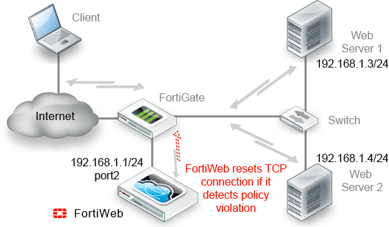
Example network topology: offline protection mode shows an example one-arm network topology for offline protection mode. A client accesses two web servers over the Internet through a FortiWeb appliance. A firewall is installed between the FortiWeb appliance and the Internet to regulate non-HTTP/HTTPS traffic. Port1 is connected to the administrator’s computer. Port2 is connected to the firewall, and thereby to a switch, which is connected to the web servers. The FortiWeb appliance provides detection, but does not load-balance, block, or otherwise modify traffic to or from the two web servers.
|
|
Alternatively, you could connect a FortiWeb appliance operating in offline protection mode to the SPAN port of a switch. |
Valid HA topologies vary by whether you use either:
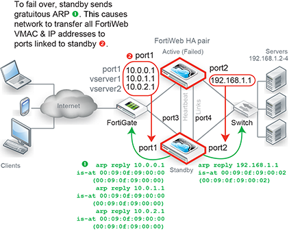
Example network topology: reverse proxy mode with HA shows another network topology for reverse proxy mode, except that the single FortiWeb appliance has been replaced with two of them operating together as an active-passive (high availability (HA) pair. If the active appliance fails, the standby appliance assumes the IP addresses and load of the failed appliance.
To carry heartbeat and synchronization traffic between the HA pair, the heartbeat interface on both HA appliances must be connected through crossover cables or through switches.
|
|
If you use a switch to connect the heartbeat interfaces, they must be reachable by Layer 2 multicast. |
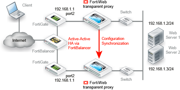
If FortiWeb will not be operating in reverse proxy mode (such as for either true transparent proxy mode or transparent inspection mode), typically you would not use FortiWeb HA — this could require changes to your network scheme, which defeats one of the key benefits of the transparent modes: it requires no IP changes. Instead, most customers use an existing external load balancer/HA solution in conjunction with FortiWeb configuration synchronization to preserve an existing active-active or active-passive topology, as shown in Example network topology: transparent proxy mode with configuration synchronization and external HA via FortiADC.
Unlike with FortiWeb HA, with external HA, that HA device must itself detect when a FortiWeb has failed in order to redirect the traffic stream. (FortiWeb has no way of actively notifying the external HA device.) To monitor the live paths through your FortiWebs, you could configure your HA device to poll either:
|
|
If you need to replicate the FortiWeb configuration without HA (i.e. no load balancing and no failover), you can achieve this by using configuration synchronization. This has no special topology requirement, except that synchronized FortiWebs should be placed in identical topologies. For more information, see Replicating the configuration without FortiWeb HA (external HA). |