Configuring and Maintaining Active-Active Supervisor Cluster
You can setup multiple Supervisors in Active-Active mode with an external Load Balancer in front. This enables you to log in to any Supervisor node and perform any GUI operation. Supervisor node functionalities are distributed across the available Supervisor nodes. An Active-Active Supervisor Cluster provides resilience against Supervisor failures, allows higher number of GUI users, Agents, Collectors, and higher volume of rule and query processing.
This document covers the following topics:
Operational Overview
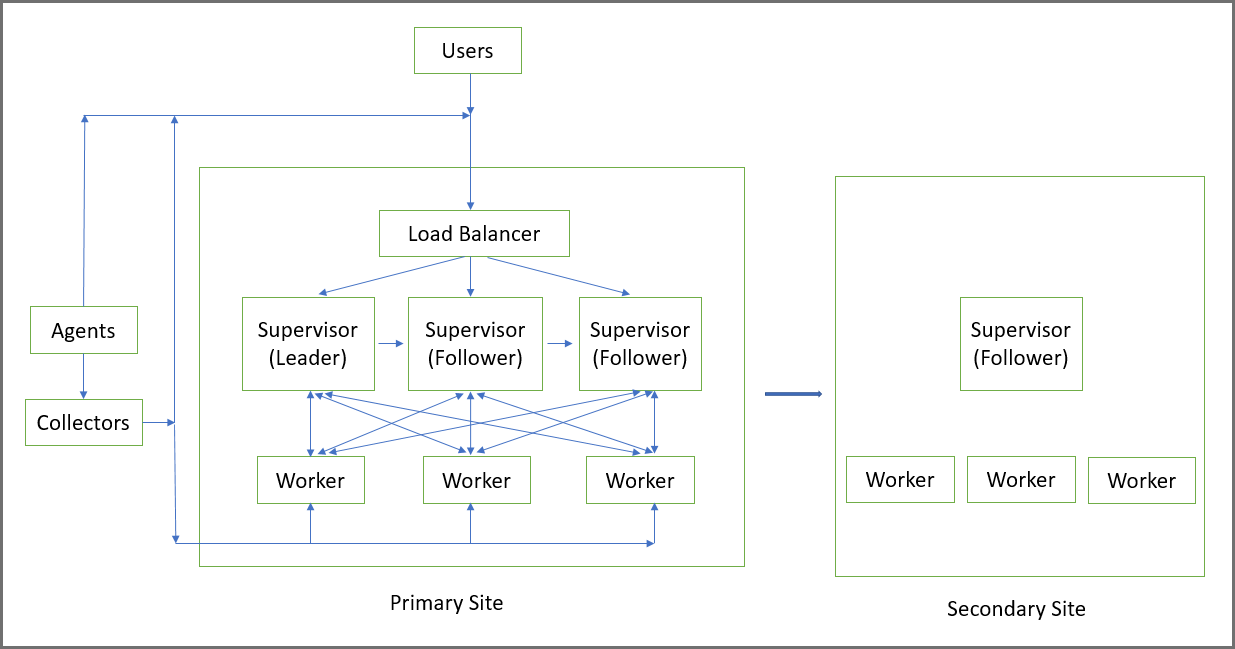
An Active-Active Supervisor cluster is built around the concept of Leader and Follower Supervisor nodes, set up as a linked list.
-
The first Supervisor where you install License, is the Leader. The Leader’s UUID matches the UUID in the installed FortiCare License. On the Leader, Redis and PostGreSQL database services run in Master mode. That means that all PostGreSQL database writes from all Supervisors go to the Leader node.
-
Next, you add a Primary Follower, which follows the Leader, in the sense that its PostGreSQL database is replicated from that of the Leader. On the Follower node, both Redis and PostGreSQL database services run in Follower (that is, read only) mode.
-
You can add another Primary Follower and it will follow the Supervisor node added in Step 2. Its PostGreSQL database is replicated from the Supervisor created in Step 2. On this node, both Redis and PostGreSQL database services run in Follower (that is, read only) mode. A replication chain is formed: Leader -> Follower in Step 2 -> Follower in Step 3.
-
You can add more Primary Follower nodes by successfully chaining from the last Follower node in the chain (in this case, the Follower node created in Step 3).
It is recommended that you put a Load Balancer in front of the Active-Active Supervisor cluster and define the Load Balancer in FortiSIEM GUI (ADMIN > Settings > Cluster Config > Supervisors). Then Collectors, Agents and GUI users can reach any of the Supervisors through the Load Balancer. Make sure that the Load Balancer address or host name is reachable from the Collectors, Agents and GUI users.
If you decide to not use a Load Balancer, you can list the Supervisors individually in ADMIN > Settings > Cluster Config > Supervisors. Make sure that the Supervisor addresses or host names are reachable from the Collectors, Agents and GUI users. A GUI user can log in to any Supervisor and use FortiSIEM.
Note that Workers to Supervisors communication is maintained internally – Workers are aware of the Supervisors and their Leader/Follower role and communicate to the appropriate node in a load balanced manner.
If the Leader Supervisor fails, then you need to login to the Follower Supervisor in the chain and promote that node to be the Leader by following the instructions in Failover Operations.
The Disaster Recovery feature works with Active-Active Supervisor Cluster. You can login to any Active-Active Supervisor and define the Supervisor for Disaster Recovery. The Primary Leader will replicate the PostGreSQL database, Profile database and SVN-lite files to the Secondary.
FortiSIEM Manager feature also works with Active-Active Supervisor Cluster. You can login to any Active-Active Supervisor and define the FortiSIEM Manager.
To upgrade an Active-Active Supervisor cluster, upgrade the Leader first and then the Followers. See the Upgrade Guide for more information.
Configuration
The following topics are available for configuration.
Adding Primary Leader
Installation
Follow the appropriate Installation Guide, available at the FortiSIEM Doc Library here. During the installation process, select 1 Supervisor at the Config Target window and complete the Installation.
Configuration
When the license is installed, the FortiSIEM unit will be recognized as the Leader. No special configuration is required. For steps on acquiring the UUID, see Collecting UUID and SSH Public Key.
Adding Primary Follower
Installation
Note that you need a High Availability License to add a Follower.
Follow the appropriate Installation Guide, available at the FortiSIEM Doc Library here. During the installation process, select 5 Supervisor Follower at the Config Target window and complete the installation.
Configuration
Note that the Primary Follower node will be added to the end of linked list of currently configured Supervisors. For example, if you currently have only one Supervisor node, then the new Follower node will follow the currently installed Supervisor (which is the Leader). If you currently have one Supervisor and one Follower node, e.g. Leader -> Follower1, then the new Follower node will follow the last Follower node, e.g. Leader -> Follower1 -> Follower2.
When you add a Follower node via the GUI, FortiSIEM will automatically detect the last Follower node and configure the new node to follow the last Follower node, which can be considered its Leader. The new Follower node needs to get the Profile database and SVN-Lite configuration from the Leader via rsync (using SSH keys). Before you begin to add the Follower node, please obtain its UUID and SSH public key using the information described. See Collecting UUID and SSH Public Key for the steps to acquire this.
To add a Follower node, take the following steps.
-
Login to GUI and navigate to ADMIN > License > Nodes.
-
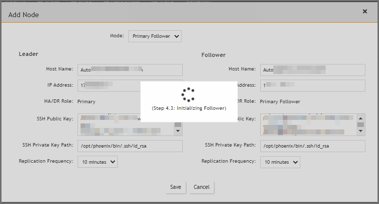
On the Add Node window, in the Mode drop-down list, select Primary Follower. FortiSIEM will automatically detect the Leader for this new node. The Leader node configuration fields appear in the left column, and the Follower node configuration fields appear in the right column.
-
Under the Follower column, enter the following information.
-
In the Host Name field, enter the host name of the Follower node.
-
In the IP Address field, enter the IP of the Follower node.
-
In the SSH Public Key field, enter/paste the SSH Public Key of the Follower node that you obtained earlier.
-
-
For the SSH Private Key Path, enter the following into the field:
/opt/phoenix/bin/.ssh/id_rsa -
For Replication Frequency, select a value indicating how frequently Profile database and SVN-lite files will be rsynced by the Follower node. The default 10 minutes is adequate for most operations.
-
Click Save.
At this point, the Primary Follower is being linked to the Primary Leader. The progress will be displayed in the GUI.
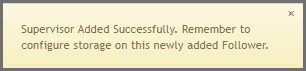
When completed, the message "Supervisor Added Successfully" will appear.
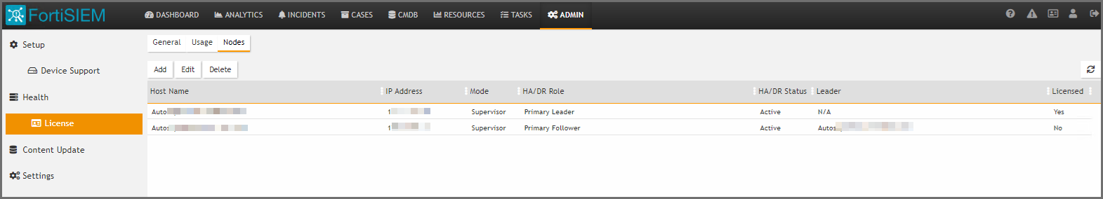
The Follower node will be added in the ADMIN > License > Nodes page.
-
If you are running ClickHouse or a Local disk setup, then you need to set up Local disk for the Primary Follower. In these cases, the Primary Follower local disk setup should be identical to that of the Primary Leader. Take the following steps:
-
Login to GUI and navigate to ADMIN > Setup > Storage.
-
Click Online and add a Local disk.
-
Click Test, then Deploy.
-
-
If you have NFS Archive setup, then you need to set up NFS Archive on the Primary Follower. The setup should be identical to that of the Primary Leader. Take the following steps:
-
Login to GUI and navigate to ADMIN > Setup > Storage.
-
Click Archive, choose NFS and add the mount point.
-
Click Test, then Deploy.
-
-
If you are running real-time Archive with HDFS, and have added Workers after the real-time Archive has been configured, then you will need to perform a Test and Deploy for HDFS Archive again from the GUI. This will enable
HDFSMgrto know about the newly added Workers.If you have set up real-time to HDFS, then you need to take the following steps to let HDFSMgr know about the Primary Follower.
-
Login to GUI.
-
Navigate to ADMIN > Setup > Storage.
-
Click Archive, and choose HDFS.
-
Click Test, then Deploy.
-
Load Balancer Setup
-
First set up an external Load Balancer in front of the Active-Active Supervisors. See External Load Balancer Configuration for a sample FortiWeb Load Balancer configuration.
-
Login to GUI and navigate to ADMIN > Settings > Cluster Config > Supervisors and add Load Balancer Host Name or IP.
Collecting UUID and SSH Public Key
-
For the UUID, obtain the Hardware ID value through an SSH session by running the following command on FortiSIEM.
/opt/phoenix/bin/phLicenseTool --show
For example:
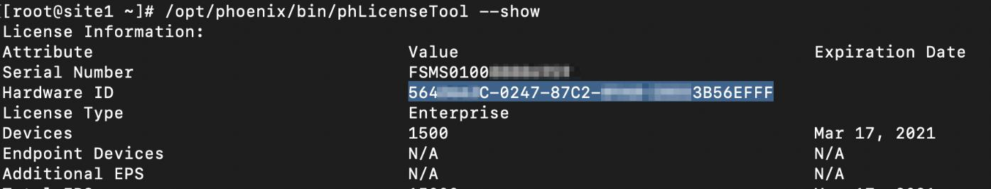
-
Enter/paste the Hardward ID into the UUID field for FortiSIEM.
-
Under Configuration and Profile Replication, generate the SSH Public Key and SSH Private Key Path by entering the following in your SSH session from FortiSIEM:
su – admin
ssh-keygen -t rsa -b 4096Leave the file location as default, and press enter at the passphrase prompt.
The output will appear similar to the following:
Generating public/private rsa key pair.
Enter file in which to save the key (/opt/phoenix/bin/.ssh/id_rsa):
Created directory '/opt/phoenix/bin/.ssh'.
Enter passphrase (empty for no passphrase):
Enter same passphrase again:
Your identification has been saved in /opt/phoenix/bin/.ssh/id_rsa.
Your public key has been saved in /opt/phoenix/bin/.ssh/id_rsa.pub.
The key fingerprint is:
a9:43:88:d1:ed:b0:99:b5:bb:e7:6d:55:44:dd:3e:48 admin@site1.fsmtesting.com
The key's randomart image is:
+--[ RSA 4096]----+
|	....|
|	. .	E. o|
-
For the SSH Public Key, enter the following command, and copy all of the output.
cat /opt/phoenix/bin/.ssh/id_rsa.pub -
Exit the admin user in the SSH session by entering the following command.
exit
External Load Balancer Configuration
This section provides guidance on how to configure FortiWEB load balancer to work with FortiSIEM Active-Active Supervisor cluster. Most load balancers can also be used. For additional information on FortiWEB configuration, see the FortiWeb documentation library. The example configuration here assumes FortiWeb will have at a minimum, two interfaces.
Port1: External network / subnet - This is where collector / user traffic connects to.
Port2: Internal network / subnet - This is where appServers and Workers reside.
In this example, VMware interfaces map to FortiWeb virtual interfaces when you deploy OVF
Virtual interface 1 is port1 in FortiWeb - 172.30.57.88/22 .1 GW
Virtual interface 2 is port2 in FortiWeb - 10.65.148.3/22
The default route: 172.30.56.1
The general configuration step are:
Define Virtual IPs
-
Navigate to Network > Virtual IP.
This is the Load Balancer IPs.
-
Define one unique free IP in the external subnet for AppServer Load Balancer and Worker Load Balancer
-
Click Create New.
-
In the Name field, enter a name, for example, " AppServerLB".
-
In the IPV4 Address field, enter your IP address. In our example, "172.30.57.89/32".
-
In the Interface field, enter/select your port. In our example,"port1".
-
Repeat steps 1 through 7 here in Define Virtual IPs for the Worker Load Balancer, then proceed to Define Virtual Server.
Define Virtual Server
-
Navigate to Server Objects > Server > Virtual Server.
-
Click Create New.
-
In the Name field, enter a name for the virtual server, for example, "AppServer_VS".
-
Click OK.
-
Under this setup, click Create New.
-
Select the Virtual IP that was created earlier.
-
Click OK.
-
In Status select Enable.
-
Leave other options default, and click OK.
Define Supervisor Health Check
-
Navigate to Server Objects > Server > Health Check.
-
Click Create New.
-
In the Name field, enter a name for the Health Check trigger, for example, "AppServerHealthCheck".
-
For Relationship, select And.
-
Click OK.
-
In Rule List, click Create New.
-
For Type, select TCP SSL and leave the options as default.
-
Click OK.
-
In Rule List, click Create New again.
-
For Type, select HTTP.
-
In the URL Path field, enter "/phoenix/login.html"
-
For Method , select GET.
-
For Match Type, select Response Code.
-
For Response Code, enter "200".
-
Click OK on each page.
Define Server Pool
-
Navigate to Server Objects > Server > Server Pool.
-
Click Create New.
-
In the Name field, enter a name for the server pool, for example, "AppServerPool".
-
For Proto , select HTTP.
-
For Type, select Reverse Proxy.
-
For Single Server / Server Balance, select Server Balance.
-
For Server Health Check, from the drop-down list, select the server health check you created in Define Supervisor Health Check.
-
For Load Balancing Algorithm, from the drop-down list, select Least Connection or Round Robin.
-
Click OK.
-
At the bottom of the page, click Create New.
-
For each Server in your server pool, in this example AppServer Pool, do the following.
-
For Status, select Enable.
-
For Server Type, select IP.
-
For IP / Domain, enter the IP address range, for example, "#.#.#.#/32".
-
For Port, enter "443".
-
For SSL, check it, but ignore client certificate.
-
Click OK.
-
Define Server Policy
-
Navigate to Policy > Server Policy.
-
In the Name field, enter a name for the server policy, for example, "AppServerPolicy".
-
For Deployment Mode, select Single Server/Server Balance.
-
For Virtual Server, select the virtual server you created in Define Virtual Server.
-
For Server Pool, select the server pool you created in Define Server Pool.
-
For HTTP Service, select HTTP.
-
For HTTPS Service, select HTTPS.
-
For Monitor Mode, enable it.
-
For Enable Traffic Log, enable it.
-
Click OK.
Define Static Routes in FortiWeb
For FortiWeb to route non HTTP/HTTPS traffic through FortiWeb, create two policy routes.
-
Navigate to Network > Route. (See https://docs.fortinet.com/document/fortiweb/7.0.2/administration-guide/55130/configuring-the-network-settings)
-
Select Policy Route.
-
Configure the following rules to allow non HTTP/HTTPS traffic inbound.
-
For If traffic matches Incoming Interface, select your port.
-
For If traffic matches Source address/mask (IPv4/IPv6), enter the IP range.
-
For If traffic matches Destination address/mask (IPv4/IPv6), enter the IP range.
-
For Force traffic to Action, select Stop Policy Routing.
-
For Force traffic to Priority, enter "200".
-
Click OK.
-
-
Configure the following rules to allow outbound traffic.
-
For If traffic matches Incoming Interface, select your port.
-
For If traffic matches Source address/mask (IPv4/IPv6), enter the IP range.
-
For If traffic matches Destination address/mask (IPv4/IPv6), enter the IP range.
-
For Force traffic to Action, select Stop Policy Routing.
-
For Force traffic to Priority, enter "100".
-
Click OK.
-
For each "AppServerIP" defined in the server pool, a FortiSIEM leader/follower cluster should use those IPs.
Maintenance
The following maintenance topics are available:
Failover Operations
Note that the Supervisors are set up as a linked list: Leader -> Follower1 -> Follower2 -> Follower3…
Case 1: Leader Node Fails
If the Leader node fails, for example, because of a hardware issue, then you need to take the following steps.
Step 1: Promote Follower1 as new Leader by following these steps.
-
SSH to Follower1 and run the following command.
phfollower2primary <ownIP>
After the script finishes, Follower1 will be the new Leader and the chain becomes: Leader (old Follower1) -> Follower2 -> Follower3
-
Login to GUI. Load Balancer will likely route to any Follower.
-
Navigate to ADMIN > License > Nodes.
-
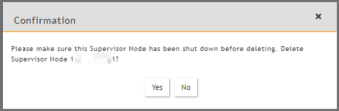
Select the old Leader node and click Delete.
-
Click Yes to confirm.
Step 2: If Disaster Recovery is enabled, then change Leader for Secondary node.
-
Login to (new Leader) Follower1 GUI.
-
Navigate to ADMIN > License > Nodes.
-
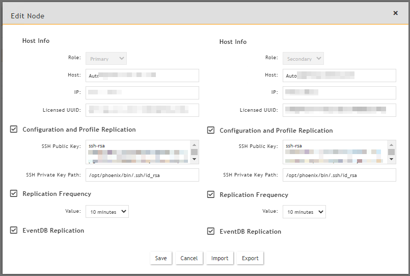
Choose Secondary node, and click Edit.
-
Enter the (new Leader) Follower1 information in the Primary column.
-
Change the Host Name field to the Follower1 Host Name.
-
Change the IP Address field to the Follower1 IP Address.
-
DO NOT change the License UUID yet. Do this after you have done a new license with Follower1's UUID in Step 4.4.
-
Set SSH Parameters (SSH Public Key, SSH Private Key Path) to that of Follower1.
-
Click Save.
-
Step 3: Install a new license with new Leader (Follower1) UUID.
Since the license is tied to failed Leader’s UUID, you will repeatedly see a message prompting you to install a new license with new Leader’s UUID within a 2 weeks grace period from the time of failure. To resolve this, take the following steps.
-
Login to (new Leader) Follower1 GUI. If you go through Load Balancer, then you may end up in Follower2 GUI which does not allow this operation.
-
Navigate to ADMIN > License > General.
-
Click Upload and provide the license file with matching (new leader) Follower1’s UUID.
Note: You cannot add new Followers to the system during the 2 weeks grace period when the Primary Leader's UUID does not match the License.
Step 4: If Disaster Recovery is enabled, update Licensed Primary UUID for Secondary node.
-
Login to (new Leader) Follower1 GUI.
-
Navigate to ADMIN > License > Nodes.
-
Choose Secondary node and click Edit.
Case 2: Follower Node Fails
If any follower node fails, take the following steps.
Step 1: Remove the failed Follower node from the Cluster.
-
Login to GUI and navigate to ADMIN > License > Nodes.
-
Select the node
-
Click Delete.
Case 3: Adding a Failed Supervisor back to Cluster
If you want to add a failed Supervisor back to the Cluster, then follow these steps.
-
Navigate to
/opt/phoenix/deployment/jumpbox. -
Clean the state data by running the following script, using its own IP.
phresetclusternode <myip>
Note: After completion, this script will reboot your appliance.
-
Once this appliance is up and running again, if the storage is Local, format the disk if you would like to reuse it, otherwise add a new disk.
-
Add the node as a Follower by following the steps in Adding Primary Follower.
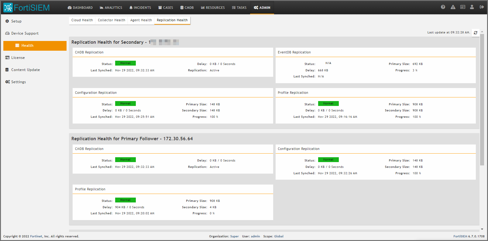
Checking Cluster Replication Health
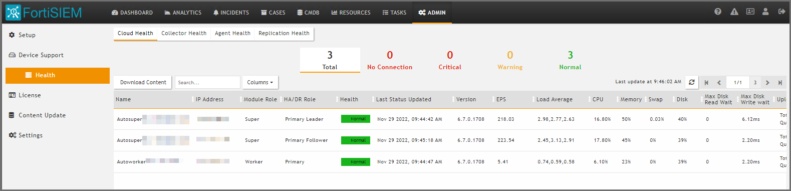
Cluster Replication health can be viewed in ADMIN > Health > Replication Health and ADMIN > Health > Cloud Health.
Maintenance Operations
Extra care must be taken to restart or shutdown a Leader node, since it contains the Master PostGreSQL database.
Case 1: Restarting Supervisor Leader
This should be avoided as much as possible, since the Leader contains the Master PostGreSQL database. App Server or any other modules on the Leader can be restarted normally.
-
Check Cluster health to make sure that Leader and Follower health are good and replication is up to date.
-
Make sure users are logged out.
-
Shutdown or Reboot the Leader node.
-
After Leader is up (that is, all processes are up), then users can login to the Leader.
-
Log on to each Follower and restart the App Server process on that node. After the App Server process is up on a Follower, users can log on to the Follower node.
Case 2: Restarting Supervisor Follower
This can be done normally. The user can login to any other Supervisor node. While the Follower node is down, the local PostGreSQL database will fall behind. If the Follower node comes back up within a reasonable time period, then PostGreSQL database replication will catch up and the system will become normal.
Case 3: Restarting a Process on any Supervisor
For any process other than DB Server on the Primary Leader, this can be done normally, and the Cluster should be up and users should be able to login. To restart the DB Server on Primary Leader, follow these steps:
-
Check Cluster health to make sure that Leader and Follower health are good and replication is up to date.
-
Make sure users are logged out.
-
Restart the DB Server on the Leader node.
-
After the DB Server on the Leader is up, restart the App Server. After both App Server and DB Server are up, then users can login to the Leader.
-
Log on to each Follower and restart the App Server process on that node. After the App Server process is up on a Follower, users can log on to the Follower node.
Case 4: Restarting Worker
This can be done normally.
Upgrade
Follow the Upgrade 6.x Cluster Deployment section from the Upgrade Guide here.
Copyright © 2024 Fortinet, Inc. All Rights Reserved. | Terms of Service | Privacy Policy