
Network topologies for managed FortiSwitch units
The FortiGate unit requires only one active FortiLink to manage all of the subtending FortiSwitch units (called stacking).
You can configure the FortiLink as a physical interface or as a logical interface (associated with one or more physical interfaces). Depending on the network topology, you can also configure a standby FortiLink.
For any of the topologies:
- All of the managed FortiSwitch units will function as one Layer-2 stack where the FortiGate unit manages each FortiSwitch separately.
- The active FortiLink carries data as well as management traffic.
Supported topologies
Fortinet recommends the following topologies for managed FortiSwitch units:
- Single FortiGate managing a single FortiSwitch unit
- Single FortiGate unit managing a stack of several FortiSwitch units
- HA-mode FortiGate units managing a single FortiSwitch unit
- HA-mode FortiGate units managing a stack of several FortiSwitch units
- HA-mode FortiGate units managing a FortiSwitch two-tier topology
- Single FortiGate unit managing multiple FortiSwitch units (using a hardware or software switch interface)
- HA-mode FortiGate units managing two-tier FortiSwitch units with access rings
- Dual-homed servers connected to a pair of FortiSwitch units using an MCLAG
- Standalone FortiGate unit with dual-homed FortiSwitch access
- HA-mode FortiGate units with dual-homed FortiSwitch access
- Multi-tiered MCLAG with HA-mode FortiGate units
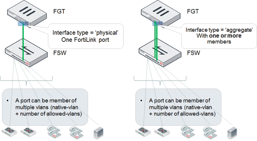
Single FortiGate managing a single FortiSwitch unit
On the FortiGate unit, the FortiLink interface is configured as physical or aggregate. The 802.3ad aggregate interface type provides a logical grouping of one or more physical interfaces.
- For the aggregate interface, you must disable the split interface on the FortiGate unit.
- When you are using the aggregate interface on the FortiGate unit for the FortiLink interface, the
lacp-modeof the FortiLink aggregate interface must be set tostatic.
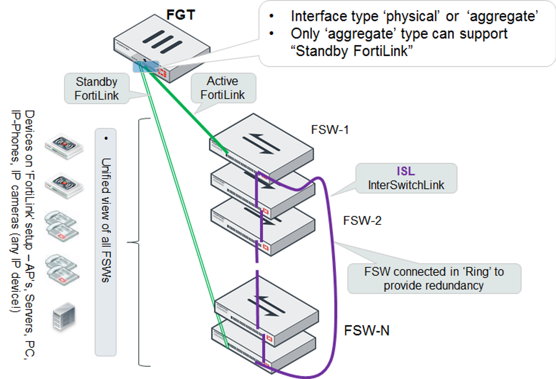
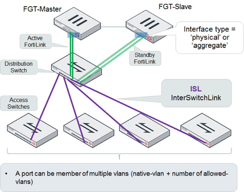
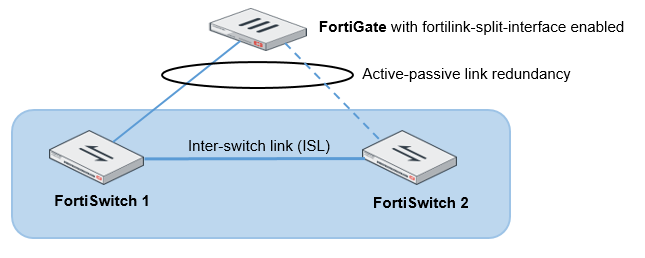
Single FortiGate unit managing a stack of several FortiSwitch units
The FortiGate unit connects directly to one FortiSwitch unit using a physical or aggregate interface. The remaining FortiSwitch units connect in a ring using inter-switch links (that is, ISL).
Optionally, you can connect a standby FortiLink connection to the last FortiSwitch unit. For this configuration, you create a FortiLink Split-Interface (an aggregate interface that contains one active link and one standby link).
- When you are using the aggregate interface on the FortiGate unit for the FortiLink interface, the
lacp-modeof the FortiLink aggregate interface must be set tostatic. - External devices shown in the following topology must be compliant endpoints, such as computers. They cannot be third-party switches or appliances.
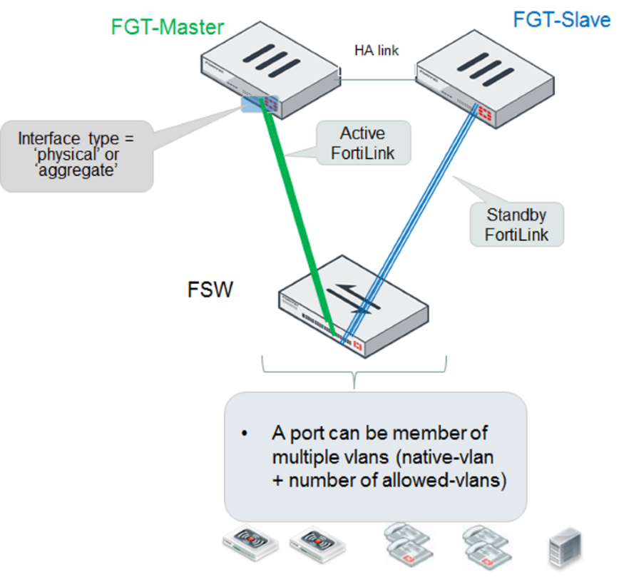
HA-mode FortiGate units managing a single FortiSwitch unit
The primary and secondary FortiGate units both connect a FortiLink to the FortiSwitch unit. The FortiLink port(s) and interface type must match on the two FortiGate units.
When using HA-mode FortiGate units to manage FortiSwitch units, the HA mode must be active-passive.
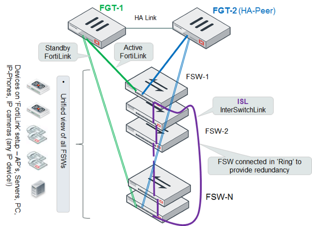
HA-mode FortiGate units managing a stack of several FortiSwitch units
The primary and secondary FortiGate units both connect a FortiLink to the first FortiSwitch unit and (optionally) to the last FortiSwitch unit. The FortiLink ports and interface type must match on the two FortiGate units.
For the active/standby FortiLink configuration, you create a FortiLink Split-Interface (an aggregate interface that contains one active link and one standby link).
- When you are using the aggregate interface on the FortiGate unit for the FortiLink interface, the
lacp-modeof the FortiLink aggregate interface must be set tostatic. - When using HA-mode FortiGate units to manage FortiSwitch units, the HA mode must be active-passive.
HA-mode FortiGate units managing a FortiSwitch two-tier topology
The distribution FortiSwitch unit connects to the primary and secondary FortiGate units. The FortiLink port(s) and interface type must match on the two FortiGate units.
When using HA-mode FortiGate units to manage FortiSwitch units, the HA mode must be active-passive.
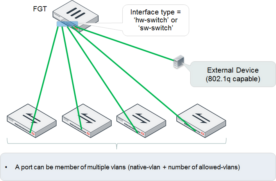
Single FortiGate unit managing multiple FortiSwitch units (using a hardware or software switch interface)
The FortiGate unit connects directly to each FortiSwitch unit. Each of these FortiLink ports is added to the logical hardware-switch or software-switch interface on the FortiGate unit.
Optionally, you can connect other devices to the FortiGate logical interface. These devices, which must support IEEE 802.1q VLAN tagging, will have Layer 2 connectivity with the FortiSwitch ports.
Using the hardware or software switch interface in FortiLink mode is not recommended in most cases. It can be used when the traffic on the ports is very light because all traffic across the switches moves through the FortiGate unit.
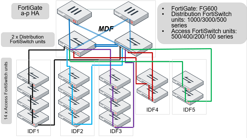
HA-mode FortiGate units managing two-tier FortiSwitch units with access rings
HA-mode FortiGate units connect to redundant distribution FortiSwitch units. Access FortiSwitch units are arranged in a stack in each IDF, connected to both distribution switches.
For the FortiLink connection to each distribution switch, you create a FortiLink split interface (an aggregate interface that contains one active link and one standby link).
- Before FortiSwitchOS 3.6.4, MCLAG was not supported when access rings were present. Starting with FortiSwitchOS 3.6.4, MCLAG is supported, even with access rings present.
- When using HA-mode FortiGate units to manage FortiSwitch units, the HA mode must be active-passive.
- When you are using the aggregate interface on the FortiGate unit for the FortiLink interface, the
lacp-modeof the FortiLink aggregate interface must be set tostatic. - This is only an example topology. Other combinations of FortiGate units and FortiSwitch units can be used to create a similar topology.
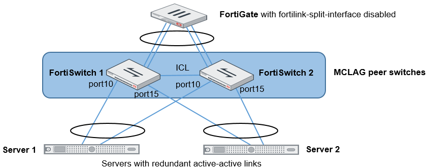
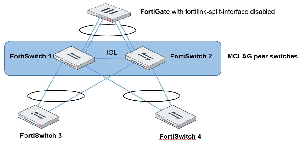
Dual-homed servers connected to a pair of FortiSwitch units using an MCLAG
To configure a multichassis LAG, you need to configure FortiSwitch 1 and FortiSwitch 2 as MCLAG peer switches before creating a two-port LAG. Use the set mclag-icl enable command to create an inter-chassis link (ICL) on each FortiSwitch unit. Then you set up two MCLAGs towards the servers, each MCLAG using one port from each FortiSwitch unit.
This topology is supported when the FortiGate unit is in HA mode.
To set up Server 1:
config switch trunk1
edit server_1
set members port10
set member mclag enable
next
To set up Server 2:
config switch trunk1
edit server_2
set members port10
set member mclag enable
next
Standalone FortiGate unit with dual-homed FortiSwitch access
This network topology provides high port density with two tiers of FortiSwitch units.
Use the set mclag-icl enable command to create an ICL on each FortiSwitch unit.
HA-mode FortiGate units with dual-homed FortiSwitch access
In HA mode, only one FortiGate is active at a time. If the active FortiGate unit fails, the backup FortiGate unit becomes active.
Use the set mclag-icl enable command to create an ICL on each FortiSwitch unit.
When using HA-mode FortiGate units to manage FortiSwitch units, the HA mode must be active-passive.

Multi-tiered MCLAG with HA-mode FortiGate units
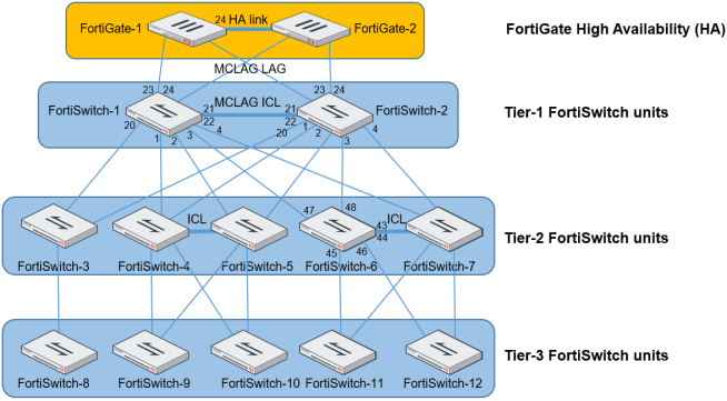
- When using HA-mode FortiGate units to manage FortiSwitch units, the HA mode must be active-passive.
-
In this topology, you must use the
auto-isl-port-groupsetting as described in the following configuration example. This setting instructs the switches to group ports from MCLAG peers together into one MCLAG when the inter-switch link (ISL) is formed. - The inter-chassis link (ICL) and
auto-isl-port-groupsettings must be done directly on the FortiSwitch unit. - CLI commands in red are manually configured.
To configure a multi-tiered MCLAG with HA-mode FortiGate units:
- Configure FortiSwitch-1 for the tier-1 MCLAG:
- Enable the ICL on the ISL formed with the MCLAG peer switch:
config switch trunk edit "D243Z14000288-0" // trunk name derived from FortiSwitch-2 SN set mode lacp-active set auto-isl 1 set mclag-icl enable set members "port21" "port22" end - Configure the two
auto-isl-port-groups based on the topology diagram. The group name must match the name that is configured on the peer switch.config switch auto-isl-port-group edit "mclag-core1" set members "port1" "port2" next edit "mclag-core2" set members "port3" "port4" end - After you complete the CLI commands in Steps 1a and 1b, the trunks are automatically formed:
config switch trunk
	edit "D243Z14000288-0"
		set mode lacp-active
		set auto-isl 1
		set mclag-icl enable
		set members "port21" "port22"
	next
	edit "__FoRtI1LiNk0__"
		set mclag enable
		set members "port24" "port23"
	next
	edit "8DN4K16000360-0" // trunk name derived from FortiSwitch-3 SN
		set mode lacp-active
		set auto-isl 1
		set mclag enable
		set members "port20"
	next
	edit "mclag-core1"
		set mode lacp-active
		set auto-isl 1
		set mclag enable
		set members "port1" "port2"
	next
	edit "mclag-core2"
		set mode lacp-active
		set auto-isl 1
		set mclag enable
		set members "port3" "port4"
	next
end
- Enable the ICL on the ISL formed with the MCLAG peer switch:
- Configure FortiSwitch-2 for the tier-1 MCLAG:
- Enable the ICL on the ISL formed with the MCLAG peer switch:
config switch trunk edit "D243Z14000289-0" // trunk name derived from FortiSwitch-1 SN set mode lacp-active set auto-isl 1 set mclag-icl enable set members "port21" "port22" end - Configure the two
auto-isl-port-groups based on the topology diagram. The group name must match the name that is configured on the peer switch.config switch auto-isl-port-group edit "mclag-core1" set members "port1" "port2" next edit "mclag-core2" set members "port3" "port4" end - After you complete the CLI commands in Steps 2a and 2b, the trunks are automatically formed:
config switch trunk
	edit "D243Z14000288-0"
		set mode lacp-active
		set auto-isl 1
		set mclag-icl enable
		set members "port21" "port22"
	next
	edit "__FoRtI1LiNk0__"
		set mclag enable
		set members "port24" "port23"
	next
	edit "8DN4K16000360-0" // trunk name derived from FortiSwitch-3 SN
		set mode lacp-active
		set auto-isl 1
		set mclag enable
		set members "port20"
	next
	edit "mclag-core1"
		set mode lacp-active
		set auto-isl 1
		set mclag enable
		set members "port1" "port2"
	next
	edit "mclag-core2"
		set mode lacp-active
		set auto-isl 1
		set mclag enable
		set members "port3" "port4"
	next
end
- Enable the ICL on the ISL formed with the MCLAG peer switch:
- Tier-2 MCLAGs. Enable the ICL between the MCLAG peers. For example, configure FortiSwitch-6 as follows.
- Change the tier-2 MCLAG peer switches to FortiLink mode and connect them to each other. Enable the ICL on the ISL formed with the MCLAG peer switches.
config switch trunk edit "8DN3X15000026-0" // trunk name derived from FortiSwitch-7 SN set mode lacp-active set auto-isl 1 set mclag-icl enable set members "port43" "port44" end - The trunks are automatically formed as below:
config switch trunk
	edit "8DN3X15000026-0"
		set mode lacp-active
		set auto-isl 1
		set mclag-icl enable
		set members "port43" "port44"
	next
	edit "8EP3X17000051-0" // trunk name derived from FortiSwitch-11 SN
		set mode lacp-active
		set auto-isl 1
		set mclag enable
		set members "port45"
	next
	edit "_FlInK1_MLAG0_"
		set mode lacp-active
		set auto-isl 1
		set mclag enable
		set members "port48" "port47"
	next
	edit "8EP3X17000069-0" // trunk name derived from FortiSwitch-12 SN
		set mode lacp-active
		set auto-isl 1
		set mclag enable
		set members "port46"
	next
end
- Change the tier-2 MCLAG peer switches to FortiLink mode and connect them to each other. Enable the ICL on the ISL formed with the MCLAG peer switches.
- Access FortiSwitch units. The access switch trunks are formed automatically as below.
On FortiSwitch-11:config switch trunk edit "_FlInK1_MLAG0_" set mode lacp-active set auto-isl 1 set mclag enable set members "port48" "port47" next end
On FortiSwitch-12:config switch trunk edit "_FlInK1_MLAG0_" set mode lacp-active set auto-isl 1 set mclag enable set members "port47" "port48" next end
Grouping FortiSwitch units
You can simplify the configuration and management of complex topologies by creating FortiSwitch groups. A group can include one or more FortiSwitch units and you can include different models in a group.
config switch-controller switch-group
edit <name>
set description <string>
set members <serial-number> <serial-number> ...
end
end
Grouping FortiSwitch units allows you to restart all of the switches in the group instead of individually. For example, you can use the following command to restart all of the FortiSwitch units in a group named my-sw-group:
execute switch-controller restart-swtp my-switch-group
Upgrading the firmware of FortiSwitch groups is easier, too, because fewer commands are needed. See Firmware upgrade of stacked or tiered FortiSwitch units.
Stacking configuration
To set up stacking:
- Configure the active FortiLink interface on the FortiGate unit.
- (Optional) Configure the standby FortiLink interface.
- Connect the FortiSwitch units together, based on your chosen topology.
1. Configure the active FortiLink
Configure the FortiLink interface (as described in the FortiLink configuration using the FortiGate GUIchapter).
When you configure the FortiLink interface, the stacking capability is enabled automatically.
2. Configure the standby FortiLink
Configure the standby FortiLink interface. Depending on your configuration, the standby FortiLink might connect to the same FortiGate unit as the active FortiLink or to a different FortiGate unit.
If the FortiGate unit receives discovery requests from two FortiSwitch units, the link from one FortiSwitch unit will be selected as active, and the link from other FortiSwitch unit will be selected as standby.
If the active FortiLink fails, the FortiGate unit converts the standby FortiLink to active.
3. Connect the FortiSwitch units
Refer to the topology diagrams to see how to connect the FortiSwitch units.
Inter-switch links (ISLs) form automatically between the stacked switches.
The FortiGate unit will discover and authorize all of the FortiSwitch units that are connected. After this, the FortiGate unit is ready to manage all of the authorized FortiSwitch units.
Disable stacking
To disable stacking, execute the following commands from the FortiGate CLI. In the following example, port4 is the FortiLink interface:
config system interface
edit port4
set fortilink-stacking disable
end
end
Firmware upgrade of stacked or tiered FortiSwitch units
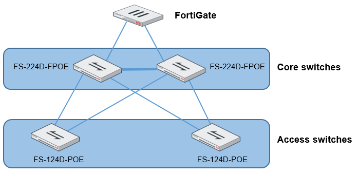
In this topology, the core FortiSwitch units are model FS-224D-FPOE, and the access FortiSwitch units are model FS-124D-POE. Because the switches are stacked or tiered, the procedure to update the firmware is simpler. In the following procedure, the four FortiSwitch units are upgraded from 3.6.1 to 3.6.2.
To upgrade the firmware of stacked or tiered FortiSwitch units:
- Check that all of the FortiSwitch units are connected and which firmware versions they are running. For example:
execute switch-controller get-conn-status

STACK-NAME: FortiSwitch-Stack-port2
SWITCH-ID         VERSION    STATUS            ADDRESS         JOIN-TIME                    NAME
S108DV2EJZDAC42F   v3.6.0     Authorized/Up    169.254.2.4     Thu Feb  8 17:07:35 2018     -
S108DV4FQON40Q07   v3.6.0     Authorized/Up    169.254.2.5     Thu Feb  8 17:08:37 2018     -
S108DVBWVLH4QGEB   v3.6.0     Authorized/Up    169.254.2.6     Thu Feb  8 17:09:13 2018     -
S108DVCY19SA0CD8   v3.6.0     Authorized/Up    169.254.2.2     Thu Feb  8 17:04:41 2018     -
S108DVD98KMQGC44*  v3.6.0     Authorized/Up    169.254.2.7     Thu Feb  8 17:10:50 2018     -
S108DVGGBJLQQO48*  v3.6.0     Authorized/Up    169.254.2.3     Thu Feb  8 17:06:57 2018     -
S108DVKM5T2QEA92   v3.6.0     Authorized/Up    169.254.2.8     Thu Feb  8 17:11:00 2018     -
S108DVZX3VTAOO45   v3.6.0     Authorized/Up    169.254.2.9     Thu Feb  8 17:11:00 2018     -

	Managed-Switches:  8        UP:  8        DOWN:  0
- Upload the firmware image for each FortiSwitch model (FS-224D-FPOE and FS-124D-POE) from either an FTP or TFTP server. If you are using a virtual domain (VDOM), you must enter the
config globalcommand before entering theupload-swtp-imagecommand. For example:FG100E4Q16004478 (global) # execute switch-controller upload-swtp-image tftp FSW_124D_POE-v3-build0382-FORTINET.out 172.30.12.18 Downloading file FSW_124D_POE-v3-build0382-FORTINET.out from tftp server 172.30.12.18... ################## Image checking ... Image MD5 calculating ... Image Saving S124DP-IMG.swtp ... Successful! File Syncing... FG100E4Q16004478 (global) # execute switch-controller upload-swtp-image tftp FSW_224D_FPOE-v3-build0382-FORTINET.out 172.30.12.18 Downloading file FSW_224D_FPOE-v3-build0382-FORTINET.out from tftp server 172.30.12.18... ###################### Image checking ... Image MD5 calculating ... Image Saving S224DF-IMG.swtp ... Successful! File Syncing...
- Check which firmware images are available. For example:
FG100E4Q16004478 (root) # execute switch-controller list-swtp-image
SWTP Images on AC:
ImageName              ImageSize(B)   ImageInfo             ImageMTime
S124DP-IMG.swtp        19174985       S124DP-v3.6-build382  Mon Oct  2 14:40:54 2017
S224DF-IMG.swtp        23277106       S224DF-v3.6-build382  Mon Oct  2 14:42:55 2017
- Stage the firmware image for each FortiSwitch model (FS-224D-FPOE and FS-124D-POE). For example:
FG100E4Q16004478 (root) # execute switch-controller stage-tiered-swtp-image ALL S124DP-IMG.swtp
Staged Image Version S124DP-v3.6-build382

FG100E4Q16004478 (root) # execute switch-controller stage-tiered-swtp-image ALL S224DF-IMG.swtp
Staged Image Version S224DF-v3.6-build382
- Check that the correct firmware image is staged for each FortiSwitch unit. For example:
diagnose switch-controller dump network-upgrade status

			Running                                Status     Next boot
__________________  ________________________________________  _________  ___________________________
VDOM : root
S108DVCY19SA0CD8  S108DV-v3.6.0-build4277,171207 (Interim) (0/0/0)       S108DV-v3.7.0-build4277,171207 (Interim)
S108DV2EJZDAC42F  S108DV-v3.6.0-build4277,171207 (Interim) (0/0/0)
- Restart the FortiSwitch units after a 2-minute delay. For example:
execute switch-controller restart-swtp-delayed ALL
- When the FortiSwitch units are running again, check that they are running the new firmware version. For example:
execute switch-controller get-conn-status

STACK-NAME: FortiSwitch-Stack-port2
SWITCH-ID         VERSION    STATUS            ADDRESS         JOIN-TIME                    NAME
S108DV2EJZDAC42F   v3.6.0     Authorized/Up    169.254.2.4     Thu Feb  8 17:07:35 2018     -
S108DV4FQON40Q07   v3.6.0     Authorized/Up    169.254.2.5     Thu Feb  8 17:08:37 2018     -
S108DVBWVLH4QGEB   v3.6.0     Authorized/Up    169.254.2.6     Thu Feb  8 17:09:13 2018     -
S108DVCY19SA0CD8   v3.6.0     Authorized/Up    169.254.2.2     Thu Feb  8 17:04:41 2018     -
S108DVD98KMQGC44*  v3.6.0     Authorized/Up    169.254.2.7     Thu Feb  8 17:10:50 2018     -
S108DVGGBJLQQO48*  v3.6.0     Authorized/Up    169.254.2.3     Thu Feb  8 17:06:57 2018     -
S108DVKM5T2QEA92   v3.6.0     Authorized/Up    169.254.2.8     Thu Feb  8 17:11:00 2018     -
S108DVZX3VTAOO45   v3.6.0     Authorized/Up    169.254.2.9     Thu Feb  8 17:11:00 2018     -

	Managed-Switches:  8        UP:  8        DOWN:  0
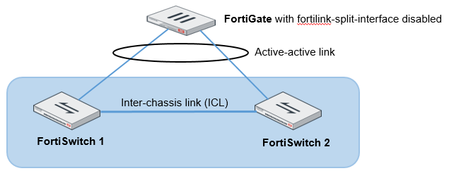
Transitioning from a FortiLink split interface to a FortiLink MCLAG
In this topology, the FortiLink split interface connects a FortiLink aggregate interface from one FortiGate unit to two FortiSwitch units.
- This procedure also applies to a FortiGate unit in HA mode.
- More links can be added between the FortiGate unit and FortiSwitch unit.
- After the MCLAG is set up, only connect the tier-2 FortiSwitch units.
-
When you are using the aggregate interface on the FortiGate unit for the FortiLink interface, the
lacp-modeof the FortiLink aggregate interface must be set tostatic.
- Enable the split interface on the FortiLink aggregate interface. By default, the split interface is enabled. For example:
config system interface
edit flinksplit1
set ip 169.254.3.1 255.255.255.0
set allowaccess ping capwap https
set vlanforward enable
set type aggregate
set member port4 port5
set lacp-mode static
set fortilink enable
set fortilink-split-interface enable
next
end
- Log into FortiSwitch 2 using the Connect to CLI button in the FortiGate GUI, use the
get switch lldp auto-isl-statuscommand to find out the name of the trunk connecting the peer switches, and change the ISL to an ICL. For example:get switch lldp auto-isl-status
config switch trunk
edit <trunk_name>
set mclag-icl enable
next
end
- Log into FortiSwitch 1 using the Connect to CLI button in the FortiGate GUI, use the
get switch lldp auto-isl-statuscommand to find out the name of the trunk connecting the peer switches, and change the ISL to an ICL. For example:get switch lldp auto-isl-status
config switch trunk
edit <trunk_name>
set mclag-icl enable
next
end
- Log into the FortiGate unit and disable the split interface. For example:
config system interface
edit flinksplit1
set fortilink-split-interface disable
next
end
- Enable the LACP active mode.
- Check that the LAG is working correctly. For example:
diagnose netlink aggregate name <aggregate_name>
Copyright © 2022 Fortinet, Inc. All Rights Reserved. | Terms of Service | Privacy Policy