
NP6 and NP6lite Acceleration
NP6 and NP6lite network processors provide fastpath acceleration by offloading communication sessions from the FortiGate CPU. When the first packet of a new session is received by an interface connected to an NP6 processor, just like any session connecting with any FortiGate interface, the session is forwarded to the FortiGate CPU where it is matched with a security policy. If the session is accepted by a security policy and if the session can be offloaded its session key is copied to the NP6 processor that received the packet. All of the rest of the packets in the session are intercepted by the NP6 processor and fast-pathed out of the FortiGate unit to their destination without ever passing through the FortiGate CPU. The result is enhanced network performance provided by the NP6 processor plus the network processing load is removed from the CPU. In addition the NP6 processor can handle some CPU intensive tasks, like IPsec VPN encryption/decryption.
|
|
NP6lite processors have the same architecture and function in the same way as NP6 processors. See NP6Lite processors. All of the descriptions of NP6 processors in this document can be applied to NP6lite possessors except where noted. |
Session keys (and IPsec SA keys) are stored in the memory of the NP6 processor that is connected to the interface that received the packet that started the session. All sessions are fast-pathed and accelerated, even if they exit the FortiGate unit through an interface connected to another NP6. There is no dependence on getting the right pair of interfaces since the offloading is done by the receiving NP6.
The key to making this possible is an Integrated Switch Fabric (ISF) that connects the NP6s and the FortiGate unit interfaces together. Many FortiGate units with NP6 processors also have an ISF. The ISF allows any port connectivity. All ports and NP6s can communicate with each other over the ISF. There are no special ingress and egress fast path requirements as long as traffic enters and exits on interfaces connected to the same ISF.
Some FortiGate units, such as the FortiGate-1000D include multiple NP6 processors that are not connected by an ISF. Because the ISF is not present fast path acceleration is supported only between interfaces connected to the same NP6 processor. Since the ISF introduces some latency, models with no ISF provide low-latency network acceleration between network interfaces connected to the same NP6 processor.
Each NP6 has a maximum throughput of 40 Gbps using 4 x 10 Gbps XAUI or Quad Serial Gigabit Media Independent Interface (QSGMII) interfaces or 3 x 10 Gbps and 16 x 1 Gbps XAUI or QSGMII interfaces.
There are at least two limitations to keep in mind:
- The capacity of each NP6 processor. An individual NP6 processor can support between 10 and 16 million sessions. This number is limited by the amount of memory the processor has. Once an NP6 processor hits its session limit, sessions that are over the limit are sent to the CPU. You can avoid this problem by as much as possible distributing incoming sessions evenly among the NP6 processors. To be able to do this you need to be aware of which interfaces connect to which NP6 processors and distribute incoming traffic accordingly.
- The NP6 processors in some FortiGate units employ NP direct technology that removes the ISF. The result is very low latency but no inter-processor connectivity requiring you to make sure that traffic to be offloaded enters and exits the FortiGate through interfaces connected to the same NP processor.
NP6 session fast path requirements
NP6 processors can offload the following traffic and services:
- IPv4 and IPv6 traffic and NAT64 and NAT46 traffic (as well as IPv4 and IPv6 versions of the following traffic types where appropriate)
- Link aggregation (LAG) (IEEE 802.3ad) traffic and traffic from static redundant interfaces (see Increasing NP6 offloading capacity using link aggregation groups (LAGs))
- TCP, UDP, ICMP and SCTP traffic
- IPsec VPN traffic, and offloading of IPsec encryption/decryption (including SHA2-256 and SHA2-512)
- NP6 processor IPsec engines support null, DES, 3DES, AES128, AES192, and AES256 encryption algorithms
- NP6 processor IPsec engines support null, MD5, SHA1, SHA256, SHA 384, and SHA512 authentication algorithms
- IPsec traffic that passes through a FortiGate without being unencrypted.
- Anomaly-based intrusion prevention, checksum offload and packet defragmentation.
- IPIP tunneling (also called IP in IP tunneling), SIT tunneling, and IPv6 tunneling sessions.
- Multicast traffic (including Multicast over IPsec).
- CAPWAP and wireless bridge traffic tunnel encapsulation to enable line rate wireless forwarding from FortiAP devices (not supported by the NP6lite).
- Traffic shaping and priority queuing for both shared and per IP traffic shaping.
- Syn proxying (not supported by the NP6lite).
- DNS session helper (not supported by the NP6lite).
- Inter-VDOM link traffic.
Sessions that are offloaded must be fast path ready. For a session to be fast path ready it must meet the following criteria:
- Layer 2 type/length must be 0x0800 for IPv4 or 0x86dd for IPv6 (IEEE 802.1q VLAN specification is supported).
- Layer 3 protocol can be IPv4 or IPv6.
- Layer 4 protocol can be UDP, TCP, ICMP, or SCTP.
- In most cases, Layer 3 / Layer 4 header or content modification sessions that require a session helper can be offloaded.
- Local host traffic (originated by the FortiGate unit) can be offloaded.
- If the FortiGate supports, NTurbo sessions can be offloaded if they are accepted by firewall policies that include IPS, Application Control, CASI, flow-based antivirus, or flow-based web filtering.
Offloading Application layer content modification is not supported. This means that sessions are not offloaded if they are accepted by firewall policies that include proxy-based virus scanning, proxy-based web filtering, DNS filtering, DLP, Anti-Spam, VoIP, ICAP, Web Application Firewall, or Proxy options.
|
|
If you disable anomaly checks by Intrusion Prevention (IPS), you can still enable hardware accelerated anomaly checks using the fp-anomaly field of the config system interface CLI command. See Configuring individual NP6 processors. |
If a session is not fast path ready, the FortiGate unit will not send the session key or IPsec SA key to the NP6 processor. Without the session key, all session key lookup by a network processor for incoming packets of that session fails, causing all session packets to be sent to the FortiGate unit’s main processing resources, and processed at normal speeds.
If a session is fast path ready, the FortiGate unit will send the session key or IPsec SA key to the network processor. Session key or IPsec SA key lookups then succeed for subsequent packets from the known session or IPsec SA.
Packet fast path requirements
Packets within the session must then also meet packet requirements.
- Incoming packets must not be fragmented.
- Outgoing packets must not require fragmentation to a size less than 385 bytes. Because of this requirement, the configured MTU (Maximum Transmission Unit) for a network processor’s network interfaces must also meet or exceed the network processors’ supported minimum MTU of 385 bytes.
Mixing fast path and non-fast path traffic
If packet requirements are not met, an individual packet will be processed by the FortiGate CPU regardless of whether other packets in the session are offloaded to the NP6.
Also, in some cases, a protocol’s session(s) may receive a mixture of offloaded and non-offloaded processing. For example, VoIP control packets may not be offloaded but VoIP data packets (voice packets) may be offloaded.
NP6Lite processors
The NP6Lite works the same way as the NP6. Being a lighter version, the NP6Lite has a lower capacity than the NP6. The NP6lite max throughput is 10 Gbps using 2x QSGMII and 2x Reduced gigabit media-independent interface (RGMII) interfaces.
Also, the NP6lite does not offload the following types of sessions:
- CAPWAP
- Syn proxy
- DNS session helper
NP6 and NP6Lite processors and sFlow and NetFlow
NP6 and NP6Lite offloading is supported when you configure NetFlow for interfaces connected to NP6 or NP6Lite processors. Offloading of other sessions is not affected by configuring NetFlow.
Configuring sFlow on any interface disables all NP6 and NP6Lite offloading for all traffic on that interface.
NP6 processors and traffic shaping
NP6-offloaded traffic supports traffic shaping just like any other traffic with one exception: configuring in bandwidth traffic shaping has no effect on NP6 accelerated traffic. In bandwidth traffic shaping sets the bandwidth limit for incoming traffic for an interface.
Out bandwidth traffic shaping is supported. Out bandwidth traffic shaping sets the bandwidth limit for outgoing traffic for an interface. You can use the following command to configure out bandwidth traffic shaping:
config system interface
edit port1
set outbandwidth 2000
end
NP Direct
On FortiGates with more than one NP6 processor, removing the Internal Switch Fabric (ISF) for NP Direct architecture provides direct access to the NP6 processors for the lowest latency forwarding. Because the NP6 processors are not connected, care must be taken with network design to make sure that all traffic to be offloaded enters and exits the FortiGate through interfaces connected to the same NP6 processor. As well Link Aggregation (LAG) interfaces should only include interfaces all connected to the same NP6 processor.
Example NP direct hardware with more than one NP6 processor includes:
- Ports 25 to 32 of the FortiGate-3700D in low latency mode.
- FortiGate-2000E
- FortiGate-2500E
Viewing your FortiGate NP6 processor configuration
Use either of the following commands to view the NP6 processor hardware configuration of your FortiGate unit:
get hardware npu np6 port-list
diagnose npu np6 port-list
If your FortiGate has NP6lite processors, you can use either of the following commands:
get hardware npu np6lite port-list
diagnose npu np6lite port-list
For example, for the FortiGate-5001D the output would be:
get hardware npu np6 port-list
Chip   XAUI Ports            Max   Cross-chip
                             Speed offloading
------ ---- -------          ----- ----------
np6_0  0    port3            10G   Yes
       1
       2    base1            1G    Yes
       3
       0-3  port1            40G   Yes
       0-3  fabric1          40G   Yes
       0-3  fabric3          40G   Yes
       0-3  fabric5          40G   Yes
------ ---- -------          ----- ----------
np6_1  0
       1    port4            10G   Yes
       2
       3    base2            1G    Yes
       0-3  port2            40G   Yes
       0-3  fabric2          40G   Yes
       0-3  fabric4          40G   Yes
------ ---- -------          ----- ----------
For more example output for different FortiGate models, see FortiGate NP6 architectures and FortiGate NP6lite architectures.
You can also use the following command to view the offloading features enabled or disabled on each of the NP6 processors in your FortiGate unit:
diagnose npu npu-feature
                    np_0      np_1
------------------- --------- ---------
Fastpath            Enabled   Enabled
Low-latency-mode    Disabled  Disabled
Low-latency-cap     No        No
IPv4 firewall       Yes       Yes
IPv6 firewall       Yes       Yes
IPv4 IPSec          Yes       Yes
IPv6 IPSec          Yes       Yes
IPv4 tunnel         Yes       Yes
IPv6 tunnel         Yes       Yes
GRE tunnel          No        No
IPv4 Multicast      Yes       Yes
IPv6 Multicast      Yes       Yes
CAPWAP              Yes       Yes
Optimizing NP6 performance by distributing traffic to XAUI links
On most FortiGate units with NP6 processors, the FortiGate interfaces are switch ports that connect to the NP6 processors with XAUI links. Packets pass from the interfaces to the NP6 processor over the XAUI links. Each NP6 processor has a 40 Gigabit bandwidth capacity. The four XAUI links each have a 10 Gigabit capacity for a total of 40 Gigabits.
On many FortiGate units with NP6 processors, the NP6 processors and the XAUI links are over-subscribed. Since the NP6 processors are connected by an Integrated Switch Fabric, you do not have control over how traffic is distributed to them. In fact traffic is distributed evenly by the ISF.
However, you can control how traffic is distributed to the XAUI links and you can optimize performance by distributing traffic evenly among the XAUI links. For example, if you have a very high amount of traffic passing between two networks, you can connect each network to interfaces connected to different XAUI links to distribute the traffic for each network to a different XAUI link.
For example, on a FortiGate-3200D (See FortiGate-3200D fast path architecture), there are 48 10-Gigabit interfaces that send and receive traffic for two NP6 processors over a total of eight 10-Gigabit XAUI links. Each XAUI link gets traffic from six 10-Gigabit FortiGate interfaces. The amount of traffic that the FortiGate-3200D can offload is limited by the number of NP6 processors and the number of XAUI links. You can optimize the amount of traffic that the FortiGate-3200D can process by distributing it evenly amount the XAUI links and the NP6 processors.
You can see the Ethernet interface, XAUI link, and NP6 configuration by entering the get hardware npu np6 port-list command. For the FortiGate-3200D the output is:
get hardware npu np6 port-list
Chip   XAUI Ports   Max   Cross-chip
                    Speed offloading
------ ---- ------- ----- ----------
np6_0  0    port1   10G   Yes
       0    port5   10G   Yes
       0    port10  10G   Yes
       0    port13  10G   Yes
       0    port17  10G   Yes
       0    port22  10G   Yes
       1    port2   10G   Yes
       1    port6   10G   Yes
       1    port9   10G   Yes
       1    port14  10G   Yes
       1    port18  10G   Yes
       1    port21  10G   Yes
       2    port3   10G   Yes
       2    port7   10G   Yes
       2    port12  10G   Yes
       2    port15  10G   Yes
       2    port19  10G   Yes
       2    port24  10G   Yes
       3    port4   10G   Yes
       3    port8   10G   Yes
       3    port11  10G   Yes
       3    port16  10G   Yes
       3    port20  10G   Yes
       3    port23  10G   Yes
------ ---- ------- ----- ----------
np6_1  0    port26  10G   Yes
       0    port29  10G   Yes
       0    port33  10G   Yes
       0    port37  10G   Yes
       0    port41  10G   Yes
       0    port45  10G   Yes
       1    port25  10G   Yes
       1    port30  10G   Yes
       1    port34  10G   Yes
       1    port38  10G   Yes
       1    port42  10G   Yes
       1    port46  10G   Yes
       2    port28  10G   Yes
       2    port31  10G   Yes
       2    port35  10G   Yes
       2    port39  10G   Yes
       2    port43  10G   Yes
       2    port47  10G   Yes
       3    port27  10G   Yes
       3    port32  10G   Yes
       3    port36  10G   Yes
       3    port40  10G   Yes
       3    port44  10G   Yes
       3    port48  10G   Yes
------ ---- ------- ----- ----------
In this command output you can see that each NP6 has for four XAUI links (0 to 3) and that each XAUI link is connected to six 10-gigabit Ethernet interfaces. To optimize throughput you should keep the amount of traffic being processed by each XAUI port to under 10 Gbps. So for example, if you want to offload traffic from four 10-gigabit networks you can connect these networks to Ethernet interfaces 1, 2, 3 and 4. This distributes the traffic from each 10-Gigabit network to a different XAUI link. Also, if you wanted to offload traffic from four more 10-Gigabit networks you could connect them to Ethernet ports 26, 25, 28, and 27. As a result each 10-Gigabit network would be connected to a different XAUI link.
Increasing NP6 offloading capacity using link aggregation groups (LAGs)
NP6 processors can offload sessions received by interfaces in link aggregation groups (LAGs) (IEEE 802.3ad). A 802.3ad Link Aggregation and it's management protocol, Link Aggregation Control Protocol (LACP) LAG combines more than one physical interface into a group that functions like a single interface with a higher capacity than a single physical interface. For example, you could use a LAG if you want to offload sessions on a 30 Gbps link by adding three 10-Gbps interfaces to the same LAG.
All offloaded traffic types are supported by LAGs, including IPsec VPN traffic. Just like with normal interfaces, traffic accepted by a LAG is offloaded by the NP6 processor connected to the interfaces in the LAG that receive the traffic to be offloaded. If all interfaces in a LAG are connected to the same NP6 processor, traffic received by that LAG is offloaded by that NP6 processor. The amount of traffic that can be offloaded is limited by the capacity of the NP6 processor.
If a FortiGate has two or more NP6 processors connected by an integrated switch fabric (ISF), you can use LAGs to increase offloading by sharing the traffic load across multiple NP6 processors. You do this by adding physical interfaces connected to different NP6 processors to the same LAG.
Adding a second NP6 processor to a LAG effectively doubles the offloading capacity of the LAG. Adding a third further increases offloading. The actual increase in offloading capacity may not actually be doubled by adding a second NP6 or tripled by adding a thrid. Traffic and load conditions and other factors may limit the actual offloading result.
The increase in offloading capacity offered by LAGs and multiple NP6s is supported by the integrated switch fabric (ISF) that allows multiple NP6 processors to share session information. Most FortiGate units with multiple NP6 processors also have an ISF. However, FortiGate models such as the 1000D, 2000E, and 2500E do not have an ISF. If you attempt to add interfaces connected to different NP6 processors to a LAG the system displays an error message.
There are also a few limitations to LAG NP6 offloading support for IPsec VPN:
- IPsec VPN anti-replay protection cannot be used if IPSec is configured on a LAG that has interfaces connected to multiple NP6 processors.
- Because the encrypted traffic for one IPsec VPN tunnel has the same 5-tuple, the traffic from one tunnel can only can be balanced to one interface in a LAG. This limits the maximum throughput for one IPsec VPN tunnel in an NP6 LAG group to 10Gbps.
NP6 processors and redundant interfaces
NP6 processors can offload sessions received by interfaces that are part of a redundant interface. You can combine two or more physical interfaces into a redundant interface to provide link redundancy. Redundant interfaces ensure connectivity if one physical interface, or the equipment on that interface, fails. In a redundant interface, traffic travels only over one interface at a time. This differs from an aggregated interface where traffic travels over all interfaces for distribution of increased bandwidth.
All offloaded traffic types are supported by redundant interfaces, including IPsec VPN traffic. Just like with normal interfaces, traffic accepted by a redundant interface is offloaded by the NP6 processor connected to the interfaces in the redundant interface that receive the traffic to be offloaded. If all interfaces in a redundant interface are connected to the same NP6 processor, traffic received by that redundant interface is offloaded by that NP6 processor. The amount of traffic that can be offloaded is limited by the capacity of the NP6 processor.
If a FortiGate has two or more NP6 processors connected by an integrated switch fabric (ISF), you can create redundant interfaces that include physical interfaces connected to different NP6 processors. However, with a redundant interface, only one of the physical interfaces is processing traffic at any given time. So you cannot use redundant interfaces to increase performance in the same way as you can with aggregate interfaces.
The ability to add redundnat interfaces connected to multiple NP6s is supported by the integrated switch fabric (ISF) that allows multiple NP6 processors to share session information. Most FortiGate units with multiple NP6 processors also have an ISF. However, FortiGate models such as the 1000D, 2000E, and 2500E do not have an ISF. If you attempt to add interfaces connected to different NP6 processors to a redundant interface the system displays an error message.
Configuring Inter-VDOM link acceleration with NP6 processors
FortiGate units with NP6 processors include inter-VDOM links that can be used to accelerate inter-VDOM link traffic.
- For a FortiGate unit with two NP6 processors there are two accelerated inter-VDOM links, each with two interfaces:
- npu0_vlink:
npu0_vlink0
npu0_vlink1 - npu1_vlink:
npu1_vlink0
npu1_vlink1
These interfaces are visible from the GUI and CLI. For a FortiGate unit with NP6 interfaces, enter the following CLI command to display the NP6-accelerated inter-VDOM links:
get system interface
...
== [ npu0_vlink0 ]
name: npu0_vlink0 mode: static ip: 0.0.0.0 0.0.0.0 status: down netbios-forward: disable type: physical sflow-sampler: disable explicit-web-proxy: disable explicit-ftp-proxy: disable mtu-override: disable wccp: disable drop-overlapped-fragment: disable drop-fragment: disable
== [ npu0_vlink1 ]
name: npu0_vlink1 mode: static ip: 0.0.0.0 0.0.0.0 status: down netbios-forward: disable type: physical sflow-sampler: disable explicit-web-proxy: disable explicit-ftp-proxy: disable mtu-override: disable wccp: disable drop-overlapped-fragment: disable drop-fragment: disable
== [ npu1_vlink0 ]
name: npu1_vlink0 mode: static ip: 0.0.0.0 0.0.0.0 status: down netbios-forward: disable type: physical sflow-sampler: disable explicit-web-proxy: disable explicit-ftp-proxy: disable mtu-override: disable wccp: disable drop-overlapped-fragment: disable drop-fragment: disable
== [ npu1_vlink1 ]
name: npu1_vlink1 mode: static ip: 0.0.0.0 0.0.0.0 status: down netbios-forward: disable type: physical sflow-sampler: disable explicit-web-proxy: disable explicit-ftp-proxy: disable mtu-override: disable wccp: disable drop-overlapped-fragment: disable drop-fragment: disable
...
By default the interfaces in each inter-VDOM link are assigned to the root VDOM. To use these interfaces to accelerate inter-VDOM link traffic, assign each interface in the pair to the VDOMs that you want to offload traffic between. For example, if you have added a VDOM named New-VDOM to a FortiGate unit with NP4 processors, you can go to System > Network > Interfaces and edit the npu0-vlink1 interface and set the Virtual Domain to New-VDOM. This results in an accelerated inter-VDOM link between root and New-VDOM. You can also do this from the CLI:
config system interface
edit npu0-vlink1
set vdom New-VDOM
end
Using VLANs to add more accelerated Inter-VDOM links
You can add VLAN interfaces to the accelerated inter-VDOM links to create inter-VDOM links between more VDOMs. For the links to work, the VLAN interfaces must be added to the same inter-VDOM link, must be on the same subnet, and must have the same VLAN ID.
For example, to accelerate inter-VDOM link traffic between VDOMs named Marketing and Engineering using VLANs with VLAN ID 100 go to System > Network > Interfaces and select Create New to create the VLAN interface associated with the Marketing VDOM:
| Name | Marketing-link |
| Type | VLAN |
| Interface | npu0_vlink0 |
| VLAN ID | 100 |
| Virtual Domain | Marketing |
| IP/Network Mask | 172.20.120.12/24 |
Create the inter-VDOM link associated with Engineering VDOM:
| Name | Engineering-link |
| Type | VLAN |
| Interface | npu0_vlink1 |
| VLAN ID | 100 |
| Virtual Domain | Engineering |
| IP/Network Mask | 172.20.120.22/24 |
Or do the same from the CLI:
config system interface
edit Marketing-link
set vdom Marketing
set ip 172.20.120.12/24
set interface npu0_vlink0
set vlanid 100
next
edit Engineering-link
set vdom Engineering
set ip 172.20.120.22/24
set interface npu0_vlink1
set vlanid 100
Confirm that the traffic is accelerated
Use the following CLI commands to obtain the interface index and then correlate them with the session entries. In the following example traffic was flowing between new accelerated inter-VDOM links and physical ports port1 and port 2 also attached to the NP6 processor.
diagnose ip address list
IP=172.31.17.76->172.31.17.76/255.255.252.0 index=5 devname=port1
IP=10.74.1.76->10.74.1.76/255.255.252.0 index=6 devname=port2
IP=172.20.120.12->172.20.120.12/255.255.255.0 index=55 devname=IVL-VLAN1_ROOT
IP=172.20.120.22->172.20.120.22/255.255.255.0 index=56 devname=IVL-VLAN1_VDOM1
diagnose sys session list
session info: proto=1 proto_state=00 duration=282 expire=24 timeout=0 session info: proto=1 proto_state=00 duration=124 expire=59 timeout=0 flags=00000000 sockflag=00000000 sockport=0 av_idx=0 use=3
origin-shaper=
reply-shaper=
per_ip_shaper=
ha_id=0 policy_dir=0 tunnel=/
state=may_dirty npu
statistic(bytes/packets/allow_err): org=180/3/1 reply=120/2/1 tuples=2
orgin->sink: org pre->post, reply pre->post dev=55->5/5->55 gwy=172.31.19.254/172.20.120.22
hook=post dir=org act=snat 10.74.2.87:768->10.2.2.2:8(172.31.17.76:62464)
hook=pre dir=reply act=dnat 10.2.2.2:62464->172.31.17.76:0(10.74.2.87:768)
misc=0 policy_id=4 id_policy_id=0 auth_info=0 chk_client_info=0 vd=0
serial=0000004e tos=ff/ff ips_view=0 app_list=0 app=0
dd_type=0 dd_mode=0
per_ip_bandwidth meter: addr=10.74.2.87, bps=880
npu_state=00000000
npu info: flag=0x81/0x81, offload=8/8, ips_offload=0/0, epid=160/218, ipid=218/160, vlan=32769/0
session info: proto=1 proto_state=00 duration=124 expire=20 timeout=0 flags=00000000 sockflag=00000000 sockport=0 av_idx=0 use=3
origin-shaper=
reply-shaper=
per_ip_shaper=
ha_id=0 policy_dir=0 tunnel=/
state=may_dirty npu
statistic(bytes/packets/allow_err): org=180/3/1 reply=120/2/1 tuples=2
orgin->sink: org pre->post, reply pre->post dev=6->56/56->6 gwy=172.20.120.12/10.74.2.87
hook=pre dir=org act=noop 10.74.2.87:768->10.2.2.2:8(0.0.0.0:0)
hook=post dir=reply act=noop 10.2.2.2:768->10.74.2.87:0(0.0.0.0:0)
misc=0 policy_id=3 id_policy_id=0 auth_info=0 chk_client_info=0 vd=1
serial=0000004d tos=ff/ff ips_view=0 app_list=0 app=0
dd_type=0 dd_mode=0
per_ip_bandwidth meter: addr=10.74.2.87, bps=880
npu_state=00000000
npu info: flag=0x81/0x81, offload=8/8, ips_offload=0/0, epid=219/161, ipid=161/219, vlan=0/32769
total session 2
Disabling offloading IPsec Diffie-Hellman key exchange
You can use the following command to disable using ASIC offloading to accelerate IPsec Diffie-Hellman key exchange for IPsec ESP traffic. By default hardware offloading is used. For debugging purposes or other reasons you may want this function to be processed by software.
Use the following command to disable using ASIC offloading for IPsec Diffie Hellman key exchange:
config system global
set ipsec-asic-offload disable
end
Configuring individual NP6 processors
You can use the config system np6 command to configure a wide range of settings for the NP6 processors in your FortiGate unit including enabling/disabling fastpath and low latency, enabling session accounting and adjusting session timeouts. As well you can set anomaly checking for IPv4 and IPv6 traffic. You can also configure different settings for each NP6 processor.
The settings that you configure for an NP6 processor with the config system np6 command apply to traffic processed by all interfaces connected to that NP6 processor. This includes the physical interfaces connected to the NP6 processor as well as all subinterfaces, VLAN interfaces, IPsec interfaces, LAGs and so on associated with the physical interfaces connected to the NP6 processor.
|
|
Some of the options for this command apply anomaly checking for NP6 sessions in the same way as the command described in Offloading NP4 anomaly detection applies anomaly checking for for NP4 sessions. |
config system np6
edit <np6-processor-name>
set fastpath {disable | enable}
set low-latency-mode {disable | enable}
set per-session-accounting {all-enable | disable | enable-by-log}
set session-timeout-random-range <range>
set garbage-session-collector {disable | enable}
set session-collector-interval <range>
set session-timeout-interval <range>
set session-timeout-random-range <range>
set session-timeout-fixed {disable | enable}
config fp-anomaly
set icmp-frag {allow | drop | trap-to-host}
set icmp-land {allow | drop | trap-to-host}
set ipv4-land {allow | drop | trap-to-host}
set ipv4-optlsrr {allow | drop | trap-to-host}
set ipv4-optrr {allow | drop | trap-to-host}
set ipv4-optsecurity {allow | drop | trap-to-host}
set ipv4-optssrr {allow | drop | trap-to-host}
set ipv4-optstream {allow | drop | trap-to-host}
set ipv4-opttimestamp {allow | drop | trap-to-host}
set ipv4-proto-err {allow | drop | trap-to-host}
set ipv4-unknopt {allow | drop | trap-to-host}
set tcp-land {allow | drop | trap-to-host}
set tcp-syn-fin {allow | drop | trap-to-host}
set tcp-winnuke {allow | drop | trap-to-host}
set tcp_fin_noack {allow | drop | trap-to-host}
set tcp_fin_only {allow | drop | trap-to-host}
set tcp_no_flag {allow | drop | trap-to-host}
set tcp_syn_data {allow | drop | trap-to-host}
set udp-land {allow | drop | trap-to-host}
end
config fp-anomaly-v6
set ipv6-daddr_err {allow | drop | trap-to-host}
set ipv6-land {allow | drop | trap-to-host}
set ipv6-optendpid {allow | drop | trap-to-host}
set ipv6-opthomeaddr {allow | drop | trap-to-host}
set ipv6-optinvld {allow | drop | trap-to-host}
set ipv6-optjumbo {allow | drop | trap-to-host}
set ipv6-optnsap {allow | drop | trap-to-host}
set ipv6-optralert {allow | drop | trap-to-host}
set ipv6-opttunnel {allow | drop | trap-to-host}
set ipv6-proto-err {allow | drop | trap-to-host}
set ipv6-saddr_err {allow | drop | trap-to-host}
set ipv6-unknopt {allow | drop | trap-to-host}
end
Command syntax
| Command | Description | Default |
|---|---|---|
fastpath {disable | enable}
|
Enable fastpath acceleration to offload sessions to the NP6 processor. You can disable fastpath if you don’t want the NP6 processor to offload sessions. | enable |
low-latency-mode {disable | enable}
|
Enable low-latency mode. In low latency mode the integrated switch fabric is bypassed. Low latency mode requires that packet enter and exit using the same NP6 processor. This option is only available for NP6 processors that can operate in low-latency mode, currently only np6_0 and np6_1 on the FortiGate-3700D and DX. | disable |
per-session-accounting {all-enable | disable | enable-by-log}
|
Disable NP6 per-session accounting or enable it and control how it works. If set to enable-by-log (the default) NP6 per-session accounting is only enabled if firewall policies accepting offloaded traffic have traffic logging enabled. If set the all-enable, NP6 per-session accounting is always enabled for all traffic offloaded by the NP6 processor. Enabling per-session accounting can affect performance. |
enable-by-log |
garbage-session-collector {disable | enable}
|
Enable deleting expired or garbage sessions. | disable |
session-collector-interval <range>
|
Set the expired or garbage session collector time interval in seconds. The range is 1 to 100 seconds. | 8 |
session-timeout-interval <range>
|
Set the timeout for inactive sessions. The range is 0 to 1000 seconds. | 40 |
session-timeout-random-range <range>
|
Set the random timeout for inactive sessions. The range is 0 to 1000 seconds. | 8 |
session-timeout-fixed {disable | enable}
|
Force session timeouts at fixed instead of random intervals. | disable |
| config fp-anomaly | ||
fp-anomaly
|
Configure how the NP6 processor does IPv4 traffic anomaly protection. You can configure the NP6 processor to allow or drop the packets associated with an attack or forward the packets that are associated with the attack to FortiOS (called “trap-to-host”). Selecting “trap-to-host” turns off NP6 anomaly protection for that anomaly. If you require anomaly protection you can enable it with a DoS policy. | |
icmp-frag {allow | drop | trap-to-host}
|
Detects Layer 3 fragmented packets that could be part of a layer 4 ICMP anomalies. | allow |
icmp-land {allow | drop | trap-to-host}
|
Detects ICMP land anomalies. | trap-to-host |
ipv4-land {allow | drop | trap-to-host}
|
Detects IPv4 land anomalies. | trap-to-host |
ipv4-optlsrr {allow | drop | trap-to-host}
|
Detects IPv4 with loose source record route option anomalies. | trap-to-host |
ipv4-optrr {allow | drop | trap-to-host}
|
Detects IPv4 with record route option anomalies. | trap-to-host |
ipv4-optsecurity {allow | drop | trap-to-host}
|
Detects security option anomalies. | trap-to-host |
ipv4-optssrr {allow | drop | trap-to-host}
|
Detects IPv4 with strict source record route option anomalies. | trap-to-host |
ipv4-optstream {allow | drop | trap-to-host}
|
Detects stream option anomalies. | trap-to-host |
ipv4-opttimestamp {allow | drop | trap-to-host}
|
Detects timestamp option anomalies. | trap-to-host |
ipv4-proto-err {allow | drop | trap-to-host}
|
Detects invalid layer 4 protocol anomalies. | trap-to-host |
ipv4-unknopt {allow | drop | trap-to-host}
|
Detects unknown option anomalies. | trap-to-host |
tcp-land {allow | drop | trap-to-host}
|
Detects TCP land anomalies. | trap-to-host |
tcp-syn-fin {allow | drop | trap-to-host}
|
Detects TCP SYN flood SYN/FIN flag set anomalies. | allow |
tcp-winnuke {allow | drop | trap-to-host}
|
Detects TCP WinNuke anomalies. | trap-to-host |
tcp_fin_noack {allow | drop | trap-to-host}
|
Detects TCP SYN flood with FIN flag set without ACK setting anomalies. | trap-to-host |
tcp_fin_only {allow | drop | trap-to-host}
|
Detects TCP SYN flood with only FIN flag set anomalies. | trap-to-host |
tcp_no_flag {allow | drop | trap-to-host}
|
Detects TCP SYN flood with no flag set anomalies. | allow |
tcp_syn_data {allow | drop | trap-to-host}
|
Detects TCP SYN flood packets with data anomalies. | allow |
udp-land {allow | drop | trap-to-host}
|
Detects UDP land anomalies. | trap-to-host |
| config fp-anomaly-v6 | ||
fp-anomaly-v6
|
Configure how the NP6 processor does IPv6 traffic anomaly protection. You can configure the NP6 processor to allow or drop the packets associated with an attack or forward the packets that are associated with the attack to FortiOS (called “trap-to-host”). Selecting “trap-to-host” turns off NP6 anomaly protection for that anomaly. If you require anomaly protection you can enable it with a DoS policy. | |
ipv6-daddr_err {allow | drop | trap-to-host}
|
Detects destination address as unspecified or loopback address anomalies. | trap-to-host |
ipv6-land {allow | drop | trap-to-host}
|
Detects IPv6 land anomalies | trap-to-host |
ipv6-optendpid {allow | drop | trap-to-host}
|
Detects end point identification anomalies. | trap-to-host |
ipv6-opthomeaddr {allow | drop | trap-to-host}
|
Detects home address option anomalies. | trap-to-host |
ipv6-optinvld {allow | drop | trap-to-host}
|
Detects invalid option anomalies. | trap-to-host |
ipv6-optjumbo {allow | drop | trap-to-host}
|
Detects jumbo options anomalies. | trap-to-host |
ipv6-optnsap {allow | drop | trap-to-host}
|
Detects network service access point address option anomalies. | trap-to-host |
ipv6-optralert {allow | drop | trap-to-host}
|
Detects router alert option anomalies. | trap-to-host |
ipv6-opttunnel {allow | drop | trap-to-host}
|
Detects tunnel encapsulation limit option anomalies. | trap-to-host |
ipv6-proto-err {allow | drop | trap-to-host}
|
Detects layer 4 invalid protocol anomalies. | trap-to-host |
ipv6-saddr_err {allow | drop | trap-to-host}
|
Detects source address as multicast anomalies. | trap-to-host |
ipv6-unknopt {allow | drop | trap-to-host}
|
Detects unknown option anomalies. | trap-to-host |
Enabling per-session accounting for offloaded NP6 sessions
For NP6 processors, you can use the following command to enable per-session accounting for the NP6_0 and -byNP6_1 NP6 processors in a FortiGate unit:
config system np6
edit np6_0
set per-session-accounting enable-by-log
next
edit np6_1
set per-session-accounting enable-by-log
end
Per session accounting is a logging feature that allows the FortiGate to report the correct bytes/pkt numbers per session for sessions offloaded to an NP6 processor. This information appears in traffic log messages as well as in FortiView. When offloaded sessions appear on the FortiView All Sessions console they include an icon identifying them as NP sessions:
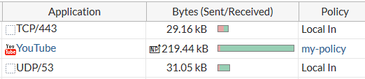
You can hover over the NP icon to see some information about the offloaded sessions.
By default, per-session-accounting is set to enable-by-log, which results in per-session accounting being turned on when you enable traffic logging in a policy. You can disable per-session accounting or set all-enable to enable per-session accounting whether or not traffic logging is enabled. Note that this configuration is set separately for each NP6 processor.
Per-session accounting can affect NP6 offloading performance. So you should only enable per-session accounting if you need the accounting information.
Enabling per-session accounting only supports traffic log messages and does not provide traffic flow data for sFlow or NetFlow.
Configure the number of IPsec engines NP6 processors use
NP6 processors use multiple IPsec engines to accelerate IPsec encryption and decryption. In some cases out of order ESP packets can cause problems if multiple IPsec engines are running. To resolve this problem you can configure all of the NP6 processors to use fewer IPsec engines.
Use the following command to change the number of IPsec engines used for decryption (ipsec-dec-subengine-mask) and encryption (ipsec-enc-subengine-mask). These settings are applied to all of the NP6 processors in the FortiGate unit.
config system npu
set ipsec-dec-subengine-mask <engine-mask>
set ipsec-enc-subengine-mask <engine-mask>
end
<engine-mask> is a hexadecimal number in the range 0x01 to 0xff where each bit represents one IPsec engine. The default <engine-mask> for both options is 0xff which means all IPsec engines are used. Add a lower <engine-mask> to use fewer engines. You can configure different engine masks for encryption and decryption.
Copyright © 2020 Fortinet, Inc. All Rights Reserved. | Terms of Service | Privacy Policy