Connecting, testing and operating the FRUP cluster
Connect to the FortiGate-100D units to the network as shown in the diagram and power them on. The FortiGate-100D units should find each other and form a cluster.
Traffic from the server (IP: 192.168.1.200) connected to port16 should pass through FGT-A (since port16 is the active-switch-port in FGT-A) and to the Internet using WAN1 (since WAN1 is the active-interface in FGT-A).
Run a sniffer on both FortiGate units using the following command:
diagnose sniffer packet any ‘icmp’ 4
interfaces=[any]
filters=[icmp]
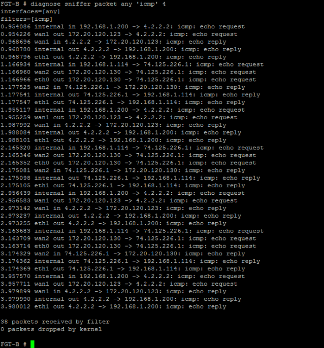
Then run a ping to 4.2.2.2 from the server. The sniffer should show results similar to the following:
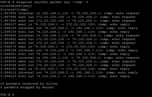
Traffic initiating from a host on the internal network (for example, IP: 192.168.1.114) connected to port14 should flow through FGT-B (since port14 is the active-switch-port in FGT-B) to the Internet using WAN2 (since WAN2 is FGT-B’s active interface).
Run the same sniffer on both FortiGate units and then run a ping to 74.125.226.1 from the internal network. The sniffer should show results similar to the following:
Shutdown FGT-A.
Traffic from the internal network should be handled by FGT-B using WAN1 and WAN2 interfaces:
To re-establish the cluster after a failover you need to restart both FortiGate-100D units. Just re-starting FGT-A may not bring the cluster back online.