Configuration overview
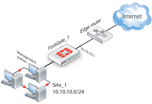
In transparent mode, all interfaces of the FortiGate unit except the management interface (which by default is assigned IP address 10.10.10.1/255.255.255.0) are invisible at the network layer. Typically, when a FortiGate unit runs in transparent mode, different network segments are connected to the FortiGate interfaces.
Figure 273 shows the management station on the same subnet. The management station can connect to the FortiGate unit directly through the web-based manager.
An edge router typically provides a public connection to the Internet and one interface of the FortiGate unit is connected to the router. If the FortiGate unit is managed from an external address (see
Figure 274), the router must translate (NAT) a routable address to direct management traffic to the FortiGate management interface.
In a transparent VPN configuration, two FortiGate units create a VPN tunnel between two separate private networks transparently. All traffic between the two networks is encrypted and protected by FortiGate security policies.
Both FortiGate units may be running in transparent mode, or one could be running in transparent mode and the other running in NAT mode. If the remote peer is running in NAT mode, it must have a static public IP address.
| VPNs between two FortiGate units running in transparent mode do not support inbound/outbound NAT (supported through CLI commands) within the tunnel. In addition, a FortiGate unit running in transparent mode cannot be used in a hub-and-spoke configuration. |
Encrypted packets from the remote VPN peer are addressed to the management interface of the local FortiGate unit. If the local FortiGate unit can reach the VPN peer locally, a static route to the VPN peer must be added to the routing table on the local FortiGate unit. If the VPN peer connects through the Internet, encrypted packets from the local FortiGate unit must be routed to the edge router instead. For information about how to add a static route to the FortiGate routing table, see the Advanced Routing .
In the example configuration shown in
Figure 274, Network Address Translation (NAT) is enabled on the router. When an encrypted packet from the remote VPN peer arrives at the router through the Internet, the router performs inbound NAT and forwards the packet to the FortiGate unit. Refer to the software supplier’s documentation to configure the router.
If you want to configure a VPN between two FortiGate units running in transparent mode, each unit must have an independent connection to a router that acts as a gateway to the Internet, and both units must be on separate networks that have a different address space. When the two networks linked by the VPN tunnel have different address spaces (see
Figure 275), at least one router must separate the two FortiGate units, unless the packets can be redirected using ICMP (see
Figure 276).
In
Figure 276, interface C behind the router is the default gateway for both FortiGate units. Packets that cannot be delivered on Network_1 are routed to interface C by default. Similarly, packets that cannot be delivered on Network_2 are routed to interface C. In this case, the router must be configured to redirect packets destined for Network_1 to interface A and redirect packets destined for Network_2 to interface B.
If there are additional routers behind the FortiGate unit (see
Figure 277) and the destination IP address of an inbound packet is on a network behind one of those routers, the FortiGate routing table must include routes to those networks. For example, in
Figure 277, the FortiGate unit must be configured with static routes to interfaces A and B in order to forward packets to Network_1 and Network_2 respectively.