Network layout and assumptions
There are four FortiGate units in this network topology acting as OSPF routers.
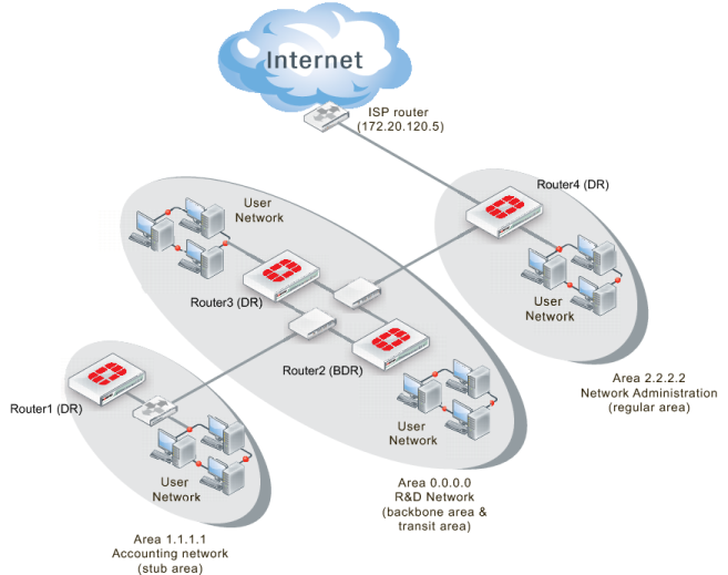
Figure 111: Advanced inter-area OSPF network topology
Area 1.1.1.1 is a stub area with one FortiGate unit OSPF router called Router1 (DR). Its only access outside of that area is a default route to the backbone area, which is how it accesses the Internet. Traffic must go from the stub area, through the backbone, to the third area to reach the Internet. The backbone area in this configuration is called a transit area. Also in area 1.1.1.1 there is a RIP router that will be providing routes to the OSPF area through redistribution.
Area 0.0.0.0 is the backbone area, and has two FortiGate unit routers named Router2 (BDR) and Router3 (DR).
Area 2.2.2.2 is a regular area that has an Internet connection accessed by both the other two OSPF areas. There is only one FortiGate unit router in this area called Router4 (DR). This area is more secure and requires MD5 authentication by routers.
All areas have user networks connected, but they are not important for configuring the network layout for this example.
Internal interfaces are connected to internal user networks only. External1 interfaces are connected to the 10.11.110.0 network, joining Area 1.1.1.1 and Area 0.0.0.0.
External2 interfaces are connected to the 10.11.111.0 network, joining Area 0.0.0.0 and Area 2.2.2.2. The ISP interface is called ISP.
Table 16: Routers, areas, interfaces, IP addresses for advanced OSPF network
Router name | Area number and type | Interface | IP address |
Router1 (DR) | 1.1.1.1 - stub area (Accounting) | port1 (internal) | 10.11.101.1 |
port2 (external1) | 10.11.110.1 |
Router2 (BDR) | 0.0.0.0 - backbone area ( R&D Network) | port1 (internal) | 10.11.102.2 |
port2 (external1) | 10.11.110.2 |
port3 (external2) | 10.11.111.2 |
Router3 (DR) | 0.0.0.0 - backbone area (R&D Network) | port1 (internal) | 10.11.103.3 |
port2 (external1) | 10.11.110.3 |
port3 (external2) | 10.11.111.3 |
Router4 (DR) | 2.2.2.2 - regular area (Network Admin) | port1 (internal) | 10.11.104.4 |
port2 (external2) | 10.11.111.4 |
port3 (ISP) | 172.20.120.4 |
Note that other subnets can be added to the internal interfaces without changing the configuration.