Network layout and assumptions
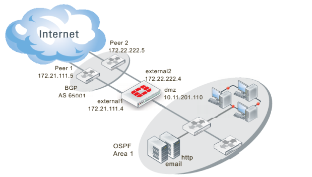
The network layout for the BGP redistributing routes example involves the company network being connected to two BGP peers as shown below. In this configuration the FortiGate unit is the BGP border router between the Company AS, and the peer routers.
The components of the layout include:
• There is only one BGP AS in this example — AS 65001, shared by the FortiGate unit and both peers.
• The Company’s FortiGate unit connects to the Internet through two BGP peers.
• The Company internal networks on the dmz interface of the FortiGate unit with an IP of 10.11.201.0/24.
• The FortiGate units’ interfaces are connected as follows:
• port1 (dmz) has IP 10.11.201.110 and is the internal user and server network
• port2 (external1) has IP 172.21.111.4 and is connected to Peer 1’s network
• port3 (external2) has IP 172.22.222.4 and is connected to Peer 2’s network
• Peer 1 has IP 172.21.111.5, and Peer 2 has IP 172.22.222.5.
• OSPF Area 1 is configured on the dmz interface of the FortiGate unit, and is the routing protocol used by the internal users and servers.