Network layout and assumptions
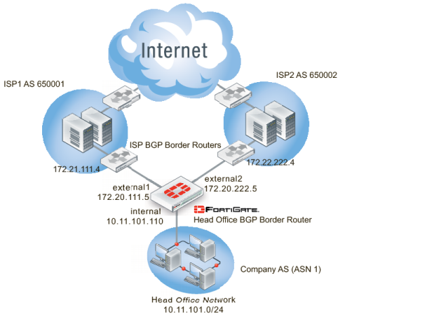
The network layout for the basic BGP example involves the company network being connected to both ISPs as shown below. In this configuration the FortiGate unit is the BGP border router between the Company AS, ISP1’s AS, and ISP2’s AS.
The components of the layout include:
• The Company AS (AS number 1) is connected to ISP1 and ISP2 through the FortiGate unit.
• The Company has one internal network — the Head Office network at 10.11.101.0/24.
• The FortiGate unit internal interface is on the the Company internal network with an IP address of 10.11.101.110.
• The FortiGate unit external1 interface is connected to ISP1’s network with an IP address of 172.20.111.5, an address supplied by the ISP.
• The FortiGate unit external2 interface is connected to IPS2’s network with an IP address of 172.20.222.5, an address supplied by the ISP.
• ISP1 AS has an AS number of 650001, and ISP2 has an AS number of 650002.
• Both ISPs are connected to the Internet.
• The ISP1 border router is a neighbor (peer) of the FortiGate unit. It has an address of 172.21.111.4.
• The ISP2 border router is a neighbor (peer) of the FortiGate unit. It has an address of 172.22.222.4.
• Apart from graceful restart, and shorter timers (holdtimer, and keepalive) default settings are to be used whenever possible.