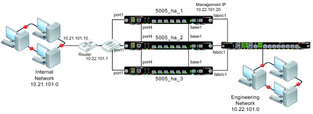
Figure 194 shows a Transparent mode FortiGate-5005FA2 HA cluster consisting of three FortiGate‑5005FA2 units (5005_ha_1, 5005_ha_2, and 5005_ha_3) installed in a FortiGate-5000 series chassis with one FortiSwitch-5003A board. The cluster applies virus scanning to traffic passing between an engineering network and an internal network. The topology includes a router that performs NAT between the internal network and the engineering network. The cluster is connected to the engineering network with an management IP address of 10.22.101.20. This IP address is on the engineering network subnet.
By default fabric1 and fabric2 are the FortiGate-5005FA2 heartbeat interfaces. This example changes the heartbeat configuration to use the base1 and port4 interfaces for the heartbeat. The base1 connection is handled using the base backplane channel switched by the FortiSwitch-5003A board. The port4 connection is handled by connecting the port4 interfaces together using a switch.
The cluster connects to the engineering network using fabric1. The FortiSwitch-5003A board provides switching for the fabric1 interfaces and the fabric1 connection to the engineering network.