NAT/Route mode active-active cluster packet flow
This section describes an example of how packets are load balanced and how failover occurs in an active-active HA cluster running in NAT/Route mode. In the example, the NAT/Route mode cluster acts as the internet firewall for a client computer’s internal network. The client computer’s default route points at the IP address of the cluster internal interface. The client connects to a web server on the Internet. Internet routing routes packets from the cluster external interface to the web server, and from the web server to the cluster external interface.
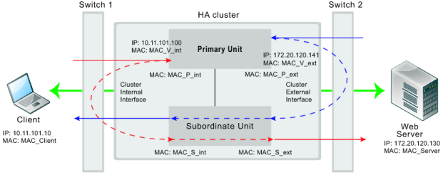
In NAT/Route mode, eight MAC addresses are involved in active-active communication between the client and the web server when the primary unit load balances packets to the subordinate unit:
• Internal virtual MAC address (MAC_V_int) assigned to the primary unit internal interface,
• External virtual MAC address (MAC_V_ext) assigned to the primary unit external interface,
• Client MAC address (MAC_Client),
• Server MAC address (MAC_Server),
• Primary unit original internal MAC address (MAC_P_int),
• Primary unit original external MAC address (MAC_P_ext),
• Subordinate unit internal MAC address (MAC_S_int),
• Subordinate unit external MAC address (MAC_S_ext).
In NAT/Route mode, the HA cluster works as a gateway when it responds to ARP requests. Therefore, the client and server only know the gateway MAC addresses. The client only knows the cluster internal virtual MAC address (MAC_V_int) and the server only knows the cluster external virtual MAC address (MAC_V_ext). The cluster virtual MAC address is described in
“Cluster virtual MAC addresses”.