This topic includes a procedure for configuring the source IP address pools used in NAT, and examples of NAT deployments. It includes the following sections:
You use the Source Pool page to create configuration objects for source IP addresses used for NAT in Layer 4 virtual server configurations.
In a Layer 4 virtual server configuration, you select a “packet forwarding method” that includes the following network address translation (NAT) options:
In a Layer 7 virtual server configuration, you do not select a packet forwarding option. Layer 7 virtual servers use NAT46 and NAT64 to support those traffic flows, but they do not use the Source Pool configuration.
See the examples that follow the procedure for illustrated usage.
Before you begin:
After you have configured a source pool IP address range configuration object, you can select it in the virtual server configuration. You can assign a virtual server multiple source pools (with the same or different source pool interface associated with it).
| Settings | Guidelines |
|---|---|
|
Name |
Configuration name. Valid characters are Note: After you initially save the configuration, you cannot edit the name. |
|
Interface |
Interface to receive responses from the backend server. The interface used for the initial client traffic is determined by the virtual server configuration. |
|
Address Type |
|
|
Address Range |
The first address in the address pool. |
|
To |
The last address in the address pool. |
| Node Member | |
| Name |
Create a node member list to be used in an HA active-active deployment. In an active-active deployment, node interfaces are configured with a list of IP addresses for all nodes in the cluster. You use this configuration to provision SNAT addresses for each of the nodes. Name is a configuration name. Valid characters are Note: After you initially save the configuration, you cannot edit the name. |
| Pool Type | IPv4 or IPv6. |
| Minimum IP | The first address in the address pool. |
| Maximum IP | The last address in the address pool. |
| Interface | Interface to receive responses from the backend server. The interface used for the initial client traffic is determined by the virtual server configuration. |
| HA Node Number | Specify the HA cluster node ID. |
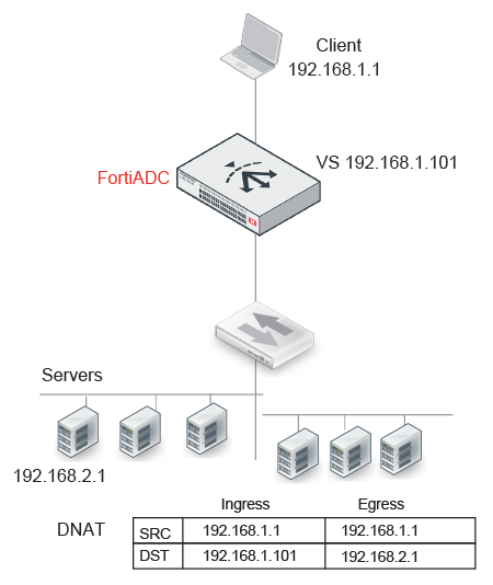
Figure 34 illustrates destination NAT (DNAT). The NAT module rewrites only the destination IP address. Therefore, if you configure destination NAT, you do not need to configure a source pool. In this DNAT example, the destination IP address in the packets it receives from the client request is the IP address of the virtual server—192.168.1.101. The NAT module translates this address to the address of the real server selected by the load balancer—in this example, 192.168.2.1. The system maintains this NAT table and performs the inverse translation when it receives the server-to-client traffic.
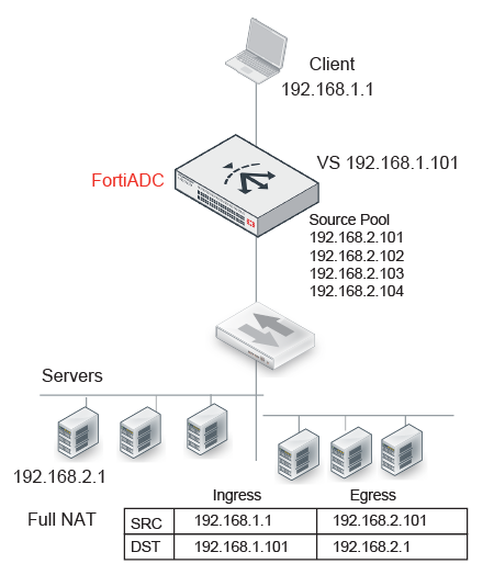
Figure 35 illustrates full NAT. The source IP / destination IP pair in the packets received is SRC 192.168.1.1 / DST 192.168.1.101. The NAT module translates the source IP address to the next available address in the source pool—in this example, 192.168.2.101. It translates the destination IP address to the address of the real server selected by the load balancer—in this example, 192.168.2.1.
The system maintains this NAT table and performs the inverse translation when it receives the server-to-client traffic.
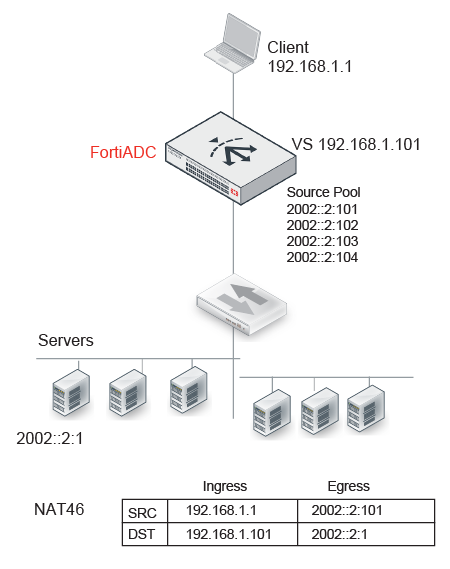
Figure 36 illustrates full NAT with NAT46. The IPv6 client connects to the virtual server IPv4 address. The source IP / destination IP pair in the packets received is SRC 192.168.1.1 / DST 192.168.1.101. The NAT module translates the source IP address to the next available IPv6 address in the source pool—in this example, 2002::2:1001. It translates the destination IP address to the IPv6 address of the real server selected by the load balancer—in this example, 2002::2:1.
The system maintains this NAT table and performs the inverse translation when it receives the server-to-client traffic.
| Features | Notes |
|---|---|
|
Profile |
Not Supported: FTP |
|
ICMP |
ICMP traffic is dropped. |
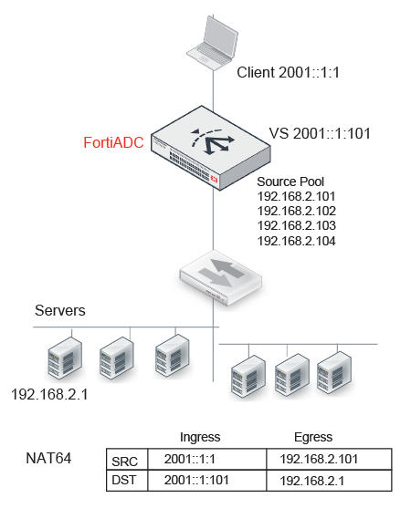
Figure 37 illustrates full NAT with NAT64. The IPv6 client connects to the virtual server IPv6 address. The source IP / destination IP pair in the packets received is SRC 2001::1:1 / DST 2001::1:101. The NAT module translates the source IP address to the next available IPv4 address in the source pool—in this example, 192.168.2.101. It translates the destination IP address to the IPv4 address of the real server selected by the load balancer—in this example, 192.168.2.1.
The system maintains this NAT table and performs the inverse translation when it receives the server-to-client traffic.
| Features | Notes |
|---|---|
|
Profiles |
Not Supported: FTP |
|
ICMP |
ICMP traffic is dropped. |
|
Security |
Not Supported: IP Reputation, DoS protection, Security logs and reports |
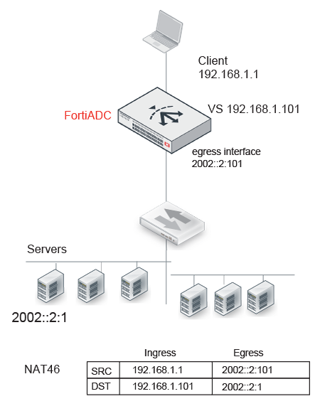
Figure 38 illustrates full NAT with NAT46. The IPv4 client connects to the virtual server IPv4 address. The source IP / destination IP pair in the packets received is SRC 192.168.1.1 / DST 192.168.1.101. The NAT module translates the source IP address to the IPv6 address of the egress interface that has IPv6 connectivity with the real server—in this example, 2002::2:1001. It translates the destination IP address to the IPv6 address of the real server selected by the load balancer—in this example, 2002::2:1.
The system maintains this NAT table and performs the inverse translation when it receives the server-to-client traffic.
| Feature | Note |
|---|---|
| Profiles | Not Supported: RADIUS, HTTP Turbo |
| Profile options | Not supported: Source Address (Using the original source IP address for the connection to the real server is contrary to the purpose of NAT.) |
| Virtual server options | Not supported: Connection Rate Limit |
| Real server pool options | Not supported: Connection Rate Limit |
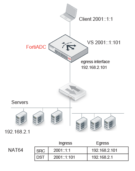
Figure 39 illustrates full NAT with NAT64. The IPv6 client connects to the virtual server IPv6 address. The source IP / destination IP pair in the packets received is SRC 2001::1:1 / DST 2001::1:101. The NAT module translates the source IP address to the IPv4 address of the egress interface that has IPv4 connectivity with the real server—in this example, 192.168.2.101. It translates the destination IP address to the IPv4 address of the real server selected by the load balancer—in this example, 192.168.2.1.
The system maintains this NAT table and performs the inverse translation when it receives the server-to-client traffic.
| Feature | Note |
|---|---|
| Profiles | Not Supported: RADIUS, HTTP Turbo |
| Profile options | Not supported: Source Address (Using the original source IP address for the connection to the real server is contrary to the purpose of NAT.) |
| Virtual server options | Not supported: Connection Rate Limit |
| Real server pool options | Not supported: Connection Rate Limit |
| Security | Not Supported: IP Reputation, DoS protection, Security logs and reports |