Figure 35: Physical and logical interfaces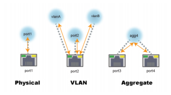
Network Interface* | IPv4 Address/Netmask | IPv6 Address/Netmask |
port1 | 192.168.1.99/24 | ::/0 |
port2 | 0.0.0.0/0 | ::/0 |
port3 | 0.0.0.0/0 | ::/0 |
port4 | 0.0.0.0/0 | ::/0 |
... | ||
* The number of physical network interfaces varies by model. | ||
Settings | Guidelines |
Common Settings | |
Name | Unique name. No spaces or special characters. After you initially save the configuration, you cannot edit the name |
Status | This Status column is not the detected physical link status; it is the administrative status (Up/Down) that indicates whether you permit the network interface to receive and/or transmit packets. |
Allow Access | Allow inbound service traffic. Select from the following options: • HTTP—Enables connections to the web UI. We recommend this option only for network interfaces connected to a trusted private network, or directly to your management computer. • HTTPS—Enables secure connections to the web UI. We recommend this option instead of HTTP. • Ping—Enables ping and traceroute to be received on this network interface. When it receives an ECHO_REQUEST (“ping”), FortiADC will reply with ICMP type 0 (ECHO_RESPONSE or “pong”). • SNMP—Enables SNMP queries to this network interface. • SSH—Enables SSH connections to the CLI. We recommend this option instead of Telnet. • Telnet—Enables Telnet connections to the CLI. We recommend this option only for network interfaces connected to a trusted private network, or directly to your management computer. |
Speed | Select one of the following speed/duplex settings: • Auto—Speed and duplex are negotiated automatically. Recommended. • 10half—10 Mbps, half duplex. • 10full—10 Mbps, full duplex. • 100half—100 Mbps, half duplex. • 100full—100 Mbps, full duplex. • 1000half—1000 Mbps, half duplex. • 1000full—1000 Mbps, full duplex. |
MTU | The default is 1500. We recommend you maintain the default. |
Virtual Domain | If applicable, select the virtual domain to which the configuration applies. |
Mode | • Static—Specify a static IP address. The IP address must be on the same subnet as the network to which the interface connects. Two network interfaces cannot have IP addresses on the same subnet (i.e. overlapping subnets). • PPPoE—Use PPPoE to retrieve a configuration for the IP address, gateway, and DNS server. For example, if this interface uses a DSL connection to the Internet, your ISP may require this option. |
Static | |
IPv4/Netmask | Specify the IP address and CIDR-formatted subnet mask, separated by a forward slash ( / ), such as 192.0.2.5/24. Dotted quad formatted subnet masks are not accepted. |
IPv6/Netmask | Specify the IP address and CIDR-formatted subnet mask, separated by a forward slash ( / ), such as 2001:0db8:85a3:::8a2e:0370:7334/64. Dotted quad formatted subnet masks are not accepted. |
Secondary IP Address | Secondary IP addresses can be used when you deploy the system so that it belongs to multiple logical subnets. If you assign multiple IP addresses to an interface, you must assign them static addresses. To add secondary IP addresses, enable the feature and save the configuration. After you have saved it the first time, you can edit it to add secondary IP addresses and enable inbound traffic to that address. |
PPPoE | |
Username | PPPoE account user name. |
Password | PPPoE account password. |
Discovery Retry Timeout | Seconds the system waits before it retries to discover the PPPoE server. The default is 5 seconds. |
DNS Server Override | Use the DNS addresses retrieved from the PPPoE server instead of the one configured in the FortiADC system settings. |
Retrieve Default Gateway | Use the default gateway retrieved from the PPPoE server instead of the one configured in the FortiADC system settings. |
Type | If you are editing the configuration for a physical interface, you cannot set the type. If you are configuring a logical interface, you can select from the following options: • Aggregate—A logical interface you create to support the aggregation of multiple physical interfaces. • VLAN—A logical interface you create to VLAN subinterfaces on a single physical interface. |
Aggregate | |
Redundant Member | Select the physical interfaces that are included in the aggregation. |
Aggregate Mode | Link aggregation type: • 802.3ad • Balance-alb • Balance-rr • Balance-tlb • Balance-xor • Broadcast |
Aggregate Algorithm | Connectivity layers that will be considered when distributing frames among the aggregated physical ports: • Layer 2 • Layer 2-3 • Layer 3-4 |
VLAN | |
Interface | Physical interface associated with the VLAN; for example, port2. |
VLAN ID | VLAN ID of packets that belong to this VLAN. If one physical network port (that is, a VLAN trunk) will handle multiple VLANs, create multiple VLAN subinterfaces on that port, one for each VLAN ID that will be received. If multiple different physical network ports will handle the same VLANs, on each of the ports, create VLAN subinterfaces that have the same VLAN IDs. The valid range is between 1 and 4094. The value you specify must match the VLAN ID added by the IEEE 802.1q-compliant router or switch connected to the VLAN subinterface. |
Secondary IP List | |
IP Address | Secondary IP addresses can be used when you deploy the system so that it belongs to multiple logical subnets. If you assign multiple IP addresses to an interface, you must assign them static addresses. To add secondary IP addresses, enable the feature and save the configuration. After you have saved it the first time, you can edit it to add secondary IP addresses and enable inbound traffic to that address. For each address, specify an IP address using the CIDR-formatted subnet mask, separated by a forward slash ( / ), such as 192.0.2.5/24. |
Allow Access | Select the services that are allowed to send inbound traffic. |
HA Node IP List | |
IP Address | You use the HA node IP list configuration in an HA active-active deployment. For each HA cluster node, configure an HA node IP list that includes an entry for each cluster node. When the appliance is in standalone mode, it uses the physical port IP address; when it is in HA mode, it uses the HA node IP address. For each address, specify an IP address using the CIDR-formatted subnet mask, separated by a forward slash ( / ), such as 192.0.2.5/24. |
Node ID | ID of the corresponding node. |
Allow Access | Select the services that are allowed to send inbound traffic. |
To configure a physical interface using the CLI: config system interface edit <port_name> set ip <ip address/netmask> set allowaccess {http https ping snmp ssh telnet} end To configure an aggregate interface using the CLI: config system interface edit <specified_name> set type agg set aggregate-mode {802.3ad | balance-alb | balance-rr | balance-tlb | balance-xor | broadcast} set aggregate-algorithm {layer2 | layer2_3 | layer3_4} set status up set member <port_name> <port_name> set ip <ip address/netmask> end To configure a VLAN interface using the CLI: config system interface edit <specified_name> set type vlan set vlanid <number> set ip <ip address/netmask> end |