Deploying an active-active cluster
This topic includes the following information:
Configuration overview
In an active-active cluster, traffic from the upstream router can be load-balanced among up to eight member nodes.
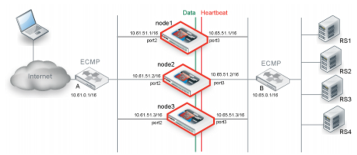
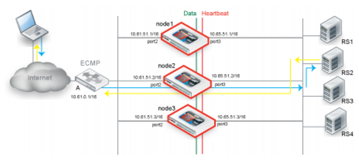
Figure 52 shows an example of an active-active cluster.
The active-active deployment depends on the equal cost multipath (ECMP) configuration on supporting routers.The routers on either side of the cluster must be configured to use ECMP to distribute traffic to the FortiADC cluster nodes. In the example, assume that the FortiADC configuration includes virtual servers belonging to subnet 10.61.0.0./24. On Router A, you configure equal cost routes as follows:
destination: 10.61.0.0/24 gateway: 10.61.51.1
destination: 10.61.0.0/24 gateway: 10.61.52.2
destination: 10.61.0.0/24 gateway: 10.61.52.3
Likewise, on Router B, you configure equal cost routes for server-to-client traffic:
destination: 0.0.0.0/0 gateway: 10.65.51.1
destination: 0.0.0.0/0 gateway: 10.65.51.2
destination: 0.0.0.0/0 gateway: 10.65.51.3
The FortiADC configuration involves the following components:
• Primary node system and feature configuration
• Interface configuration (HA node IP list)
• HA configuration
One of the nodes in the cluster is selected as the primary node, and the others are member nodes. In this example, node1 is the primary node and node2 and node3 are member nodes. When the cluster is formed, the configuration for node1 is pushed to node2 and node3.
When you configure network interfaces, in addition to a primary IP address, you configure an HA node IP list that specifies special HA IP addresses of each node in the cluster. The HA node IP list for port2 in the example has the following values:
10.61.51.1/16 node1
10.61.51.2/16 node3
10.61.51.2/16 node3
Likewise, the HA node IP list for port3 has the following values:
10.65.51.1/16 node1
10.65.51.2/16 node3
10.65.51.2/16 node3
Finally, you log into each node when it is in standalone mode to configure its HA settings. When you are ready to form the cluster, change the setting to HA active-active. The system state changes when a node joins a cluster.
Note: The example shows routers on both sides of the FortiADC cluster. Your deployment might not have a router between the FortiADC cluster and the real server pool. In this case, if your real servers support load balancing methods like ECMP, the expected behavior is the same as what is described here. If not, it is expected that the real servers route reply traffic to the cluster node that sent them the client traffic.
Limitations
FTP has both a control connection and a data connection associated with client-server communication. The two “channels” make it difficult to support asymmetric routes in an active-active cluster. Therefore, the network topology for a deployment to support FTP servers may not include a router between the FortiADC cluster and the real servers. The real servers must be configured to send response traffic back to the FortiADC cluster member that forwarded it the request.
Figure 53shows a network topology with an active-active cluster that supports FTP traffic.
Basic steps
To deploy an active-active cluster:
1. License all FortiADC appliances in the HA cluster, and register them, including FortiGuard services, with the Fortinet Technical Support web site:
2. Physically link the FortiADC appliances that make up the HA cluster.
You must link at least one of their ports (for example, port4 to port4) for heartbeat and synchronization traffic between members of the cluster. You can do either of the following:
• If only two nodes, connect the two appliances directly with a crossover cable.
• If more than two nodes, link the appliances through a switch. If connected through a switch, the interfaces must be reachable by Layer 2 multicast.
3. Configure member nodes:
a. Log into the member nodes as the admin user.
Important: Set the Device Priority to a higher number than the primary node; for example, set Device Priority to 2.
4. Configure the primary node:
a. Log into the primary node as the admin user.
b. Configure network interfaces so that each traffic interface has an HA node IP address list in addition to its physical port IP address. See
“Configuring network interfaces”.
When HA is set to standalone, the system uses the physical port IP address. When HA is set to active-active, the system uses the HA node IP address.
c. Complete the configuration for all features, as well as the HA configuration.
Important: Set Device Priority to a lower number than the member nodes; for example, set Device Priority to 1.
Note: After you have saved the HA configuration changes, cluster members might join or rejoin the cluster. After you have save configuration changes on the primary node, it automatically pushes its configuration to the member nodes.
Expected behavior
In active-active deployments, be sure to enable data synchronization. In particular, enable the following settings:
• Sync L4 Connection—Sychronizes TCP connection state data.
• Sync L4 Persistent—Synchronizes Layer 4 source IP address data.
• Sync L7 Persistent—Syncronizes Layer 7 source IP address data.
The sections that follow describe how the cluster uses synchronized data.
Traffic to Layer 4 virtual servers
When Layer 4 synchronization is enabled, the cluster nodes share TCP connection state and Layer 4 source IP address data for traffic to Layer 4 virtual servers (and Layer 2 TCP and Turbo HTTP virtual servers, which are packet-based). The node that receives the first SYN packet forwards the traffic to the real server, and, at the same time, multicasts the Layer 4 session data to the other nodes in the cluster.
Figure 54 illustrates the sequence of the traffic flow when client-to-server and server-to-client session traffic are routed through the same node.
1. Router A uses ECMP to select a cluster node to which to forward a client connection request for a virtual server IP address—in this case, node1.
2. The cluster node forwards the traffic to a real server and multicasts the session data to the cluster via the data port.
3. Router B uses ECMP to select a cluster node to which to forward the server response traffic—in this case, also node1.
4. The cluster node forwards the traffic to the client and multicasts the session data to the cluster via the data port.
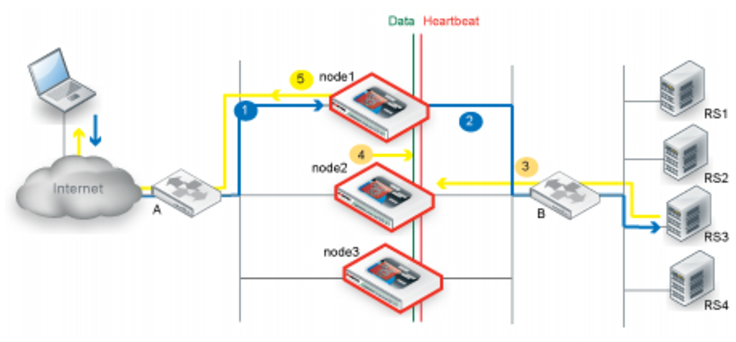
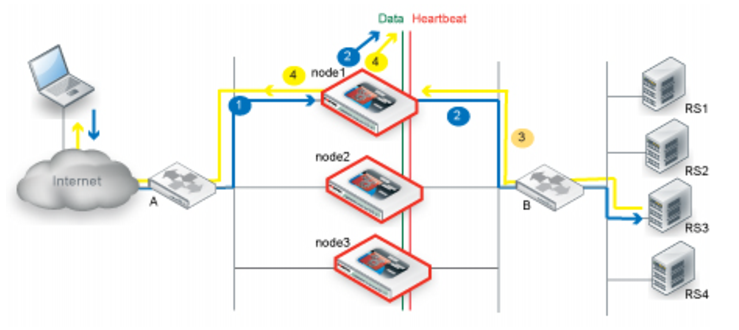
Figure 55 illustrates the sequence of the traffic flow when client-to-server and server-to-client session traffic are routed through different nodes and synchronization has occurred before the second node receives the server-to-client traffic.
1. Router A uses ECMP to select a cluster node to which to forward a client connection request for a virtual server IP address—in this case, node1.
2. The cluster node forwards the traffic to a real server and multicasts the session data to the cluster via the data port.
3. Router B uses ECMP to select a cluster node to which to forward the server response traffic. In this case, it selects node2.
4. If the session has already been synchronized between node1 and node2, node2 forwards the traffic to the client and multicasts the session data to the cluster via the data port.
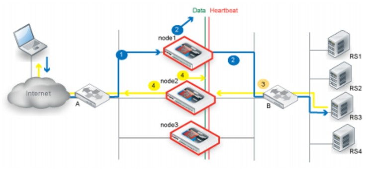
Figure 56 illustrates the sequence of the traffic flow when client-to-server and server-to-client session traffic are routed through different nodes and synchronization has not yet occurred when the second node receives the server-to-client traffic.
1. Router A uses ECMP to select a cluster node to which to forward a client connection request for a virtual server IP address—in this case, node1.
2. The cluster node forwards the traffic to a real server and multicasts the session data to the cluster via the data port.
3. Router B uses ECMP to select a cluster node to which to forward the server response traffic. In this case, it selects node2.
4. Because the session has not yet been synchronized between node1 and node2, node2 multicasts the traffic to the cluster.
5. When node1 receives traffic from node2, it forwards the traffic to the client and multicasts the session data via the data port.
Traffic to Layer 7 virtual servers
When Layer 7 synchronization is enabled, the cluster nodes share source IP data for traffic to Layer 7 virtual servers (and Layer 2 HTTP virtual servers) based on whether the virtual server profile Source option is enabled.
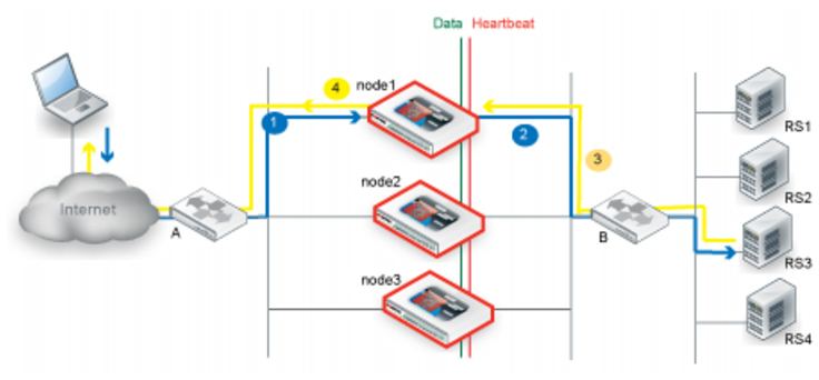
Figure 57 illustrates the sequence of the traffic flow when the Source option is not enabled.
1. Router A uses ECMP to select a cluster node to which to forward a client connection request to a virtual server destination IP address—in this case, node1.
2. The cluster node forwards the traffic to a real server. Because the Source option was not enabled, the source IP address in the FortiADC-to-real-server traffic is the node1 HA cluster node IP address, and this becomes the destination IP address for the server-to-client traffic.
3. Router B does not use ECMP; instead, it forwards the traffic to the node1 HA cluster IP address.
4. The cluster node finds the real client IP address in its session table and forwards the traffic to the client.
Figure 58 illustrates the sequence of the traffic flow when the Source option is enabled.
1. Router A uses ECMP to select a cluster node to which to forward a client connection request to a virtual server destination IP address—in this case, node1.
2. The cluster node forwards the traffic to a real server. Because the Source option is enabled, the source IP address in the FortiADC-to-real-server traffic is the true client IP address, and this becomes the destination IP address for the server-to-client traffic.
3. Router B uses ECMP and might forward the traffic to any node in the cluster. In this example, it forwards the traffic to node2.
4. Because the server-to-client response was not expected by node2, it multicasts the traffic to the cluster.
5. When node1 receives the server-to-client response data from node2, it forwards the traffic to the client.
Note: In an active-active deployment, the virtual server profile Source option adds latency to the transaction. To reduce latency, use an alternative to the Source option, such as the X-Forwarded-For option, if you have a requirement that the original client IP be logged by the real server.
Traffic processed by firewall rules
Some traffic through the FortiADC is processed by the firewall rules only and not by server load balancing rules—for example, traffic with a destination IP address that is the real server IP address, not the virtual server IP address. In an active-active deployment, firewall traffic is always forwarded through the primary node only.
Figure 59 illustrates the sequence of the firewall traffic flow when ECMP results in traffic being forwarded through the primary node.
1. Router A uses ECMP to select a cluster node to which to forward a client connection request to a real server destination IP address. In this case, it selects the primary node, node1.
2. The primary node forwards the traffic to a real server.
3. Router B uses ECMP to select a cluster node to which to forward the server response traffic—in this case, also node1.
4. The primary node forwards the traffic to the client.
Figure 60 illustrates the sequence of the firewall traffic flow when ECMP results in an asymmetric route.
1. Router A uses ECMP to select a cluster node to which to forward a client connection request to a real server destination IP address. In this case, it selects the primary node, node1.
2. The cluster node forwards the traffic to a real server.
3. Router B uses ECMP to select a cluster node to which to forward the server response traffic—in this case, node2.
4. Because the server-to-client response was not expected by node2, it forwards traffic to the cluster.
5. When the primary node receives traffic from node2, it forwards it to the client.
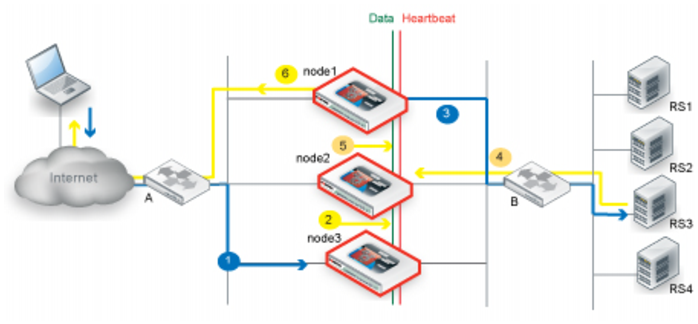
Figure 61 illustrates the sequence of the firewall traffic flow when ECMP results in client-to-server traffic sent to a non-primary node.
1. Router A uses ECMP to select a cluster node to which to forward a client connection request to a real server destination IP address. In this case, it selects a member node, node3.
2. Firewall traffic is forwarded by the primary node only, so node3 multicasts the session data to the cluster via the data port
3. The primary node forwards the traffic to a real server.
4. Router B uses ECMP to select a cluster node to which to forward the server response traffic—in this case, node2.
5. Because the server-to-client response was not expected by node2, it forwards traffic to the cluster.
6. When the primary node receives traffic from node2, it forwards it to the client.
Best practice tips
The following tips are best practices:
• Be careful to maintain the heartbeat link(s). If the heartbeat is accidentally interrupted, such as when a network cable is temporarily disconnected, the other nodes assume that the primary node has failed. In an active-active deployment, a new primary node is elected among member nodes. If no failure has actually occurred, both nodes can be operating as primary nodes simultaneously.
• If you link HA appliances through switches, to improve fault tolerance and reliability, link the ports through two separate switches. Also, do not connect these switches to your overall network, which could introduce a potential attack point, and could also allow network load to cause latency in the heartbeat, which could cause an unintentional failover.
 occurred
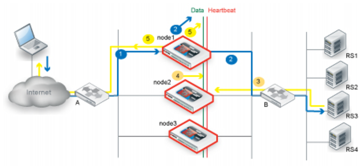 occurred