Figure 6: HA topology and failover — IP address transfer to the new active appliance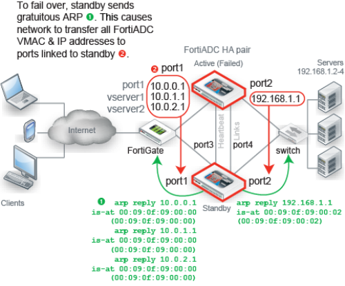
FortiADC-VM supports HA. However, if you do not wish to use the native HA, you can use your hypervisor or VM environment manager to install your virtual appliances over a hardware cluster to improve availability. For example, VMware clusters can use vMotion or VMware HA. |
For best fault tolerance, make sure that your topology is fully redundant, with no single points of failure. For example, in Figure 6, the switch, firewall, and Internet connection are all single points of failure. If any should fail, web sites would be unavailable, despite the HA cluster. To prevent this, you would add a dual ISP connection to separate service providers, preferably with their own redundant pathways upstream. You would also add a standby firewall, and a standby switch. |
Maintain the heartbeat link(s). If the heartbeat is accidentally interrupted for an active-passive HA group, such as when a network cable is temporarily disconnected, the secondary appliance will assume that the primary unit has failed, and become the new primary appliance. If no failure has actually occurred, both FortiADC appliances will be operating as primary appliances simultaneously. |
To avoid unintentional failovers due to accidental detachment or hardware failure of a single heartbeat link, make two heartbeat links. For example, you might link port3 to port3 on the other appliance, and link port4 to port4 on the other appliance, then configure both appliances to use those network interfaces for heartbeat and synchronization. |
If you link HA appliances through switches, to improve fault tolerance and reliability, link the ports through two separate switches. Do not connect these switches to your overall network, which could introduce a potential attack point, and could also allow network load to cause latency in the heartbeat, which could cause an unintentional failover. |
Setting name | Description |
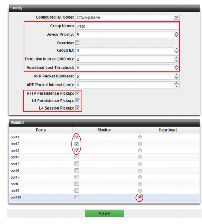
Group Name | Type a name to identify the HA pair if you have more than one. This setting is optional, and does not affect HA function. The maximum length is 35 characters. |
Device Priority | Type the priority of the appliance when electing the primary appliance in the HA pair. (On standby devices, this setting can be reconfigured using the CLI command execute ha manage <serial-number_str> <priority_int>. This setting is optional. The smaller the number, the higher the priority. The valid range is 0 to 9. The default is 5. Note: By default, unless you enable Override, uptime is more important than this setting. For details, see “How HA chooses the active appliance”. |
Override | Enable to make Device Priority a more important factor than uptime when selecting the main appliance. See “How HA chooses the active appliance”. |
Group ID | Type a number that identifies the HA pair. Both members of the HA pair must have the same group ID. If you have more than one HA pair on the same network, each HA pair must have a different group ID. Changing the group ID changes the cluster’s virtual MAC address. The valid range is 0 to 63. The default value is 0. |
Detection Interval | Type the number of 100-millisecond intervals to set the pause between each heartbeat packet that the one FortiADC appliance sends to the other FortiADC appliance in the HA pair. This is also the amount of time that a FortiADC appliance waits before expecting to receive a heartbeat packet from the other appliance. This part of the configuration is synchronized between the active appliance and standby appliance. The valid range is 1 to 20 (that is, between 100 and 2,000 milliseconds). Note: Although this setting is synchronized between the main and standby appliances, you should initially configure both appliances with the same Detection Interval to prevent inadvertent failover from occurring before the initial synchronization. |
Heartbeat Lost Threshold | Type the number of times one of HA appliances retries the heartbeat and waits to receive HA heartbeat packets from the other HA appliance before assuming that the other appliance has failed. This part of the configuration is synchronized between the main appliance and standby appliance. Normally, you do not need to change this setting. Exceptions include: • Increase the failure detection threshold if a failure is detected when none has actually occurred. For example, during peak traffic times, if the main appliance is very busy, it might not respond to heartbeat packets in time, and the standby appliance may assume that the main appliance has failed. • Reduce the failure detection threshold or detection interval if administrators and HTTP clients have to wait too long before being able to connect through the main appliance, resulting in noticeable down time. The valid range is from 1 to 60. Note: Although this setting is synchronized between the main and standby appliances, you should initially configure both appliances with the same Heartbeat Lost Threshold to prevent inadvertent failover from occurring before the initial synchronization. |
HTTP Persistence Pickup | Enable to synchronize HTTP sessions with the standby appliance, allowing for seamless traffic without interruptions if failover occurs. This impacts performance. Enable it only if you require uninterrupted HTTP sessions. If your applications are sessionless, or use server-size sessions, this may not be required. |
L4 Persistence Pickup | Enable to synchronize TCP connections with the standby appliance allowing for seamless traffic without interruptions if failover occurs. This impacts performance. Enable it only if you require uninterrupted TCP connections. Normally, if packets missing and receipt is not acknowledged (ACK), the mechanism of the TCP protocol requires that the missing packet be re-sent. However, if the existence of the connection itself is not synchronized, the client may be required to re-initialize a connection if this option is not enabled. |
L4 Session Pickup | Enable to synchronize IP layer sessions with the standby appliance allowing for seamless traffic without interruptions if failover occurs. This impacts performance. Enable it only if you require uninterrupted IP sessions. |
Port Monitor | Mark the check boxes of one or more network interfaces that each directly correlate with a physical link. These ports will be monitored for link failure. Port monitoring (also called interface monitoring) monitors physical network ports to verify that they are functioning properly and linked to their networks. If the physical port fails or the cable becomes disconnected, a failover occurs. You can monitor physical interfaces and 802.3ad aggregated interfaces, but not VLAN subinterfaces. Note: To prevent an unintentional failover, do not configure port monitoring until you configure HA on both appliances in the HA pair, and have plugged in the cables to link the physical network ports that will be monitored. |
Heartbeat Interface | Select which port(s) on this appliance that the main and standby appliances will use to send heartbeat signals and synchronization data between each other (i.e. the HA heartbeat link). Connect this port to the same port number on the other member of the HA cluster. (e.g., If you select port3 for the primary heartbeat link, connect port3 on this appliance to port3 on the other appliance.) At least one heartbeat interface must be selected on each appliance in the HA cluster. Ports that currently have an IP address assigned for other purposes (that is, virtual servers or bridges) cannot be re-used as a heartbeat link. Tip: If enough ports are available, you can select both a primary heartbeat interface and a secondary heartbeat interface on each appliance in the HA pair to provide heartbeat link redundancy. (You cannot use the same port as both the primary and secondary heartbeat interface on the same appliance, as this is incompatible with the purpose of link redundancy.) Note: If a switch is used to connect the heartbeat interfaces, the heartbeat interfaces must be reachable by Layer 2 multicast. |
Setting name | Description |
ARP Packet Numbers | Type the number of times that the FortiADC appliance will broadcast extra address resolution protocol (ARP) packets when it takes on the main role. (Even though a new NIC has not actually been connected to the network, FortiADC does this to notify the network that a new physical port has become associated with the IP address and virtual MAC of the HA pair.) This is sometimes called “using gratuitous ARP packets to train the network,” and can occur when the main appliance is starting up, or during a failover. Also configure ARP Packet Interval. Normally, you do not need to change this setting. Exceptions include: • Increase the number of times the main appliance sends gratuitous ARP packets if your HA pair takes a long time to fail over or to train the network. Sending more gratuitous ARP packets may help the failover to happen faster. • Decrease the number of times the main appliance sends gratuitous ARP packets if your HA pair has a large number of VLAN interfaces and virtual domains. Because gratuitous ARP packets are broadcast, sending them may generate a large amount of network traffic. As long as the HA pair still fails over successfully, you could reduce the number of times gratuitous ARP packets are sent to reduce the amount of traffic produced by a failover. The valid range is 1 to 16. |
ARP Packet Interval | Type the number of seconds to wait between each broadcast of ARP packets. Normally, you do not need to change this setting. Exceptions include: • Decrease the interval if your HA pair takes a long time to fail over or to train the network. Sending ARP packets more frequently may help the failover to happen faster. • Increase the interval if your HA pair has a large number of VLAN interfaces and virtual domains. Because gratuitous ARP packets are broadcast, sending them may generate a large amount of network traffic. As long as the HA pair still fails over successfully, you could increase the interval between when gratuitous ARP packets are sent to reduce the rate of traffic produced by a failover. The valid range is from 1 to 20. |